CN210868532U - Heat radiation structure of LED display screen box door leaf - Google Patents
Heat radiation structure of LED display screen box door leaf Download PDFInfo
- Publication number
- CN210868532U CN210868532U CN201921361907.5U CN201921361907U CN210868532U CN 210868532 U CN210868532 U CN 210868532U CN 201921361907 U CN201921361907 U CN 201921361907U CN 210868532 U CN210868532 U CN 210868532U
- Authority
- CN
- China
- Prior art keywords
- door leaf
- led display
- box body
- plate
- display screen
- Prior art date
- Legal status (The legal status is an assumption and is not a legal conclusion. Google has not performed a legal analysis and makes no representation as to the accuracy of the status listed.)
- Active
Links
Images


Abstract
The utility model relates to a heat radiation structure of LED display screen box door leaf, it includes box frame and box door leaf, a plurality of LED display module assembly fixed connection are on this link, form a thermal-arrest chamber in this box frame at the back of a plurality of these LED display module assembly simultaneously, this box door leaf includes outer door leaf board and interior welt, wherein, this interior welt is erect on the medial surface of this outer door leaf board, form a ventilation cooling way simultaneously between this interior welt and this outer door leaf board, this ventilation cooling way is linked together with this thermal-arrest chamber, this ventilation cooling property has income wind gap and air outlet, wherein, this income wind gap sets up in this thermal-arrest chamber, this air outlet sets up on this outer door leaf board.
Description
Technical Field
The utility model relates to a heat radiation structure especially indicates an use heat radiation structure in LED display screen box door leaf.
Background
The LED display screen is a flat panel display, is formed by splicing a plurality of small LED module panels, and is equipment for displaying various information such as characters, images, videos, video signals and the like. At present, the LED display screen has been widely used in many fields such as outdoor advertisement display and product image display. When specifically using, the staff generally can piece together a plurality of small-size LED display screen each other and form information such as a large-scale whole display screen to the external display characters, image, video, and this kind of large-scale whole display screen can promote the size of display screen, and then promotes demonstration, bandwagon effect.
In practice, in order to expand the display range and the display size of the LED display screen, a user can greatly increase the number of small LED module panels, and when a large number of LED module panels are assembled together, the problem of concentrated heat dissipation is troublesome.
SUMMERY OF THE UTILITY MODEL
The utility model discloses the technical scheme who adopts does: the utility model provides a heat radiation structure of LED display screen box door leaf, it includes box frame and box door leaf, wherein, this box frame includes outer frame body and link, this outer frame body is fixed to be set up around this link, a plurality of LED display module fixed connection are on this link, the back of a plurality of these LED display module is unified towards this box frame's rear, erect a plurality of these LED display module in this box frame through this link, back at a plurality of these LED display module forms a thermal-arrest chamber in this box frame simultaneously, in work, a plurality of these LED display module circular telegram are luminous, its light shines away to the place ahead, and the produced heat of a plurality of these LED display module work is mainly concentrated in this thermal-arrest chamber.
The box door leaf is pivoted on the box frame, and in the specific implementation, the two box door leaves are respectively pivoted on two sides of the box frame.
This box door leaf has and opens and closed two kinds of states, and when this box door leaf was in the open mode, this thermal-arrest chamber was opened, and at this moment, a plurality of these LED display module expose and conveniently overhaul and maintain, and when this box door leaf was in the closed mode, this thermal-arrest chamber was sealed, and at this moment, seal, sealed waterproof and safety protection to this thermal-arrest chamber through this box door leaf.
The box door leaf comprises an outer door leaf plate and an inner lining plate, wherein the inner lining plate is erected on the inner side face of the outer door leaf plate, a ventilation and heat dissipation channel is formed between the inner lining plate and the outer door leaf plate, the ventilation and heat dissipation channel is communicated with the heat collection cavity, the ventilation and heat dissipation channel is provided with an air inlet and an air outlet, the air inlet is arranged in the heat collection cavity, and the air outlet is arranged on the outer door leaf plate.
The inner lining plate is provided with a lining plate inner side face and a lining plate outer side face, the ventilation heat dissipation channel is arranged between the lining plate outer side face and the inner side face of the outer door leaf plate, a box body heat source part is fixedly connected to the lining plate inner side face, meanwhile, the box body heat source part is arranged in the heat collection cavity, in specific implementation, the box body heat source part is an electronic element with larger heat productivity, such as a power supply, a power supply box, a control circuit board and a driving part of an LED display screen, and during working, air flow in the ventilation heat dissipation channel flows, the air flow flows in from the air inlet and then flows out from the air outlet, in the process, partial heat generated by the working of the box body heat source part is directly transmitted to the heat collection cavity, ventilation heat dissipation is carried out by means of the flowing of the air flow in the ventilation heat dissipation channel, and the other part of heat generated by the working of the, and then the inner lining plate is ventilated and radiated by the airflow in the ventilation and heat radiation channel.
When the concrete implementation, this outer door leaf board is parallel to each other with this interior welt to make the air current in this ventilation heat dissipation way flow smoothly, when the concrete implementation, this inlet port department is provided with the fan, with the velocity of flow that promotes this ventilation heat dissipation way air current, this fan passes through the frame cover to be fixed on the medial surface of this outer door leaf board, when the concrete implementation, this box heat source part passes through the fixed strip to be fixed on this welt medial surface, when the concrete implementation, this air outlet opening is downwards and the concave setting in this outer door leaf board, in order to reach waterproof effect.
In practical application, an air inlet duct is formed between the inner lining plate and the outer door leaf plate, the air inlet duct is communicated with the heat collecting cavity, the air inlet duct is provided with an inlet and an outlet, wherein, the inlet is arranged on the outer door leaf plate, the outlet is arranged on the inner lining plate, the airflow flows in the air inlet duct, and when air enters, the ventilation and cooling channel and the air inlet channel can be formed simultaneously by arranging the inner lining plate on the inner side surface of the outer door leaf plate, the whole structure is simple, the ventilation and heat dissipation effects on the inner lining plate are excellent, the inlet and the air outlet have the same structure, the inlet opening is downwards and concavely arranged in the outer door leaf plate so as to achieve a waterproof effect, and when the door is implemented, waterproof rubber strips are arranged on the periphery of the outer door leaf plate, and a door lock is further arranged on the outer door leaf plate.
The utility model has the advantages that: the utility model discloses a this box heat source part is the power of LED display screen, the power pack, control circuit board, the great electronic component of calorific capacity such as drive division, in the time of work, the air current in this ventilation cooling way flows, the air current flows in from this income wind gap then flows by this air outlet, in this process, the produced partial heat of this box heat source part work directly conducts in this thermal-arrest chamber, then carry out the ventilation and heat dissipation with the help of the flow of air current in this ventilation cooling way, the produced another partial heat of this box heat source part work directly conducts on this interior welt, then carry out ventilation and heat dissipation to this interior welt with the help of the flow of air current in this ventilation cooling way.
Drawings
Fig. 1 is a schematic perspective view of the present invention.
Fig. 2 is a schematic view of the three-dimensional exploded structure of the box door leaf of the present invention.
Fig. 3 is a rear view of the box door leaf of the present invention.
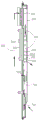
Fig. 4 is a schematic sectional view of the door leaf of the box body of the present invention.
Detailed Description
As shown in fig. 1 to 4, a heat dissipation structure of a cabinet door leaf of an LED display screen includes a cabinet frame 100 and a cabinet door leaf 200, wherein the cabinet frame 100 includes an outer frame 110 and a connecting frame 120.
The outer frame 110 is fixedly disposed around the connection frame 120.
The plurality of LED display modules are fixedly connected to the connecting frame 120, and the back surfaces of the plurality of LED display modules face the rear of the case frame 100.
A plurality of LED display modules are mounted in the case frame 100 through the connection frame 120.
A heat collecting chamber 300 is formed in the case frame 100 at the same time at the back of a plurality of the LED display modules.
When the LED display module works, the LED display modules are electrified to emit light, the light rays are radiated forwards, and the heat generated by the working of the LED display modules is mainly concentrated in the heat collecting cavity 300.
The box door 200 is pivotally connected to the box frame 100, and in an implementation, two box doors 200 are pivotally connected to two sides of the box frame 100 respectively.
This box door leaf 200 has opening and closed two kinds of states, and when this box door leaf 200 was in the open mode, this thermal-arrest chamber 300 was opened, and at this moment, a plurality of these LED display module expose and conveniently overhaul and maintain, and when this box door leaf 200 was in the closed mode, this thermal-arrest chamber 300 was sealed, and at this moment, seal, waterproof seal and safety protection to this thermal-arrest chamber 300 through this box door leaf 200.
The box door 200 includes an outer door panel 210 and an inner lining panel 220, wherein the inner lining panel 220 is disposed on an inner side 211 of the outer door panel 210, and a ventilation and heat dissipation channel 400 is formed between the inner lining panel 220 and the outer door panel 210.
The ventilation heat sink 400 is communicated with the heat collecting chamber 300.
The ventilation duct 400 has an air inlet 410 and an air outlet 420, wherein the air inlet 410 is disposed in the heat collecting cavity 300, and the air outlet 420 is disposed on the outer door panel 210.
The inner lining plate 220 has a lining plate inner side 221 and a lining plate outer side 222, and the ventilation heat sink 400 is located between the lining plate outer side 222 and the inner side 211 of the outer door leaf 210.
The case heat source portion 500 is fixedly coupled to the inner side 221 of the lining panel while the case heat source portion 500 is seated in the heat collecting chamber 300.
In practical implementation, the heat source portion 500 of the box body is an electronic component with a large heat generation quantity, such as a power supply, a power supply box, a control circuit board, a driving portion, and the like of the LED display screen.
In operation, the air flow in the ventilation heat sink 400 flows, and the air flow flows in from the air inlet 410 and then flows out from the air outlet 420, during which a portion of heat generated by the operation of the case body heat source portion 500 is directly conducted to the heat collecting chamber 300, and then ventilation heat dissipation is performed by the flow of the air flow in the ventilation heat sink 400.
Another portion of heat generated by the operation of the case heat source part 500 is directly transferred to the inner lining plate 220, and then the inner lining plate 220 is ventilated and radiated by the flow of the air flow in the ventilation heat radiating duct 400.
In one embodiment, the outer door panel 210 and the inner lining panel 220 are parallel to each other, so that the air flow in the ventilation/heat dissipation channel 400 can be smoothly performed.
In an implementation, a fan 610 is disposed at the air inlet 410 to increase the flow rate of the air flowing in the ventilation heat-dissipation duct 400.
The fan 610 is fixed to the inner side 211 of the outer door panel 210 by a frame cover 611.
In practice, the heat source portion 500 of the cabinet is secured to the inner side 221 of the liner panel by a securing strap 620.
In practical implementation, the air outlet 420 is opened downward and is recessed in the outer door panel 210, so as to achieve the waterproof effect.
In an implementation, an air inlet duct 700 is further formed between the inner lining plate 220 and the outer door panel 210, the air inlet duct 700 is communicated with the heat collecting cavity 300, the air inlet duct 700 has an inlet 710 and an outlet 720, wherein the inlet 710 is disposed on the outer door panel 210, the outlet 720 is disposed on the inner lining plate 220, and the air flow flows through the air inlet duct 700, and the air inlet can ventilate and cool the inner lining plate 220.
The utility model discloses an erect this interior welt 220 on the medial surface 211 of this outer door leaf board 210, just can form this ventilation cooling way 400 and this air inlet duct 700 simultaneously, its overall structure is simple, and is splendid to the ventilation cooling effect of this interior welt 220.
The inlet 710 has the same structure as the air outlet 420, and the inlet 710 has a downward opening and is recessed in the outer door panel 210 to achieve the waterproof effect.
In specific implementation, the outer door leaf 210 is provided with waterproof rubber strips 630 around the outer door leaf 210, and the outer door leaf 210 is further provided with a door lock 640.
Claims (10)
1. The utility model provides a heat radiation structure of LED display screen box door leaf, it includes box frame and box door leaf, wherein, this box frame includes outer frame body and link, and this outer frame body is fixed to be set up around this link, and a plurality of LED display module fixed connection are on this link, and the back of a plurality of these LED display module is unified towards this box frame's rear, erects a plurality of these LED display module in this box frame through this link, its characterized in that:
a heat collecting cavity is formed in the box body frame at the back of a plurality of LED display modules at the same time,
the box door leaf comprises an outer door leaf plate and an inner lining plate, wherein the inner lining plate is erected on the inner side surface of the outer door leaf plate, a ventilation and heat dissipation channel is formed between the inner lining plate and the outer door leaf plate and is communicated with the heat collection cavity, the ventilation and heat dissipation channel is provided with an air inlet and an air outlet, the air inlet is arranged in the heat collection cavity, the air outlet is arranged on the outer door leaf plate,
the inner lining plate is provided with a lining plate inner side face and a lining plate outer side face, the ventilation and heat dissipation channel is located between the lining plate outer side face and the inner side face of the outer door leaf plate, the box body heat source part is fixedly connected to the lining plate inner side face, and meanwhile, the box body heat source part is located in the heat collection cavity.
2. The heat dissipation structure of the LED display screen box body door leaf as claimed in claim 1, wherein: an air inlet duct is formed between the inner lining plate and the outer door leaf plate, the air inlet duct is communicated with the heat collection cavity, the air inlet duct is provided with an inlet and an outlet, the inlet is arranged on the outer door leaf plate, and the outlet is arranged on the inner lining plate.
3. The heat dissipation structure of the LED display screen box body door leaf as claimed in claim 2, wherein: the outer door leaf plate and the inner lining plate are parallel to each other.
4. The heat dissipation structure of the LED display screen box body door leaf as claimed in claim 2, wherein: the air inlet is provided with a fan which is fixed on the inner side surface of the outer door leaf plate through a frame cover.
5. The heat dissipation structure of the LED display screen box body door leaf as claimed in claim 2, wherein: the heat source part of the box body is fixed on the inner side surface of the lining plate through a fixing strip.
6. The heat dissipation structure of the LED display screen box body door leaf as claimed in claim 2, wherein: the inlet and the air outlet are both opened downwards and are concavely arranged in the outer door leaf plate.
7. The heat dissipation structure of the LED display screen box body door leaf as claimed in claim 2, wherein: the box door leaf is pivoted on the box frame.
8. The heat dissipation structure of the LED display screen box body door leaf as claimed in claim 7, wherein: two door leaves of the box body are respectively pivoted on two sides of the frame of the box body.
9. The heat dissipation structure of the LED display screen box body door leaf as claimed in claim 1, wherein: waterproof rubber strips are arranged around the outer door leaf plate.
10. The heat dissipation structure of the LED display screen box body door leaf as claimed in claim 1, wherein: the outer door leaf plate is provided with a door lock.
Priority Applications (1)
| Application Number | Priority Date | Filing Date | Title |
|---|---|---|---|
| CN201921361907.5U CN210868532U (en) | 2019-08-21 | 2019-08-21 | Heat radiation structure of LED display screen box door leaf |
Applications Claiming Priority (1)
| Application Number | Priority Date | Filing Date | Title |
|---|---|---|---|
| CN201921361907.5U CN210868532U (en) | 2019-08-21 | 2019-08-21 | Heat radiation structure of LED display screen box door leaf |
Publications (1)
| Publication Number | Publication Date |
|---|---|
| CN210868532U true CN210868532U (en) | 2020-06-26 |
Family
ID=71286108
Family Applications (1)
| Application Number | Title | Priority Date | Filing Date |
|---|---|---|---|
| CN201921361907.5U Active CN210868532U (en) | 2019-08-21 | 2019-08-21 | Heat radiation structure of LED display screen box door leaf |
Country Status (1)
| Country | Link |
|---|---|
| CN (1) | CN210868532U (en) |
Cited By (1)
| Publication number | Priority date | Publication date | Assignee | Title |
|---|---|---|---|---|
| CN110402071A (en) * | 2019-08-21 | 2019-11-01 | 深圳市齐普光电子股份有限公司 | A kind of radiator structure of LED display cabinet door leaf |
-
2019
- 2019-08-21 CN CN201921361907.5U patent/CN210868532U/en active Active
Cited By (2)
| Publication number | Priority date | Publication date | Assignee | Title |
|---|---|---|---|---|
| CN110402071A (en) * | 2019-08-21 | 2019-11-01 | 深圳市齐普光电子股份有限公司 | A kind of radiator structure of LED display cabinet door leaf |
| CN110402071B (en) * | 2019-08-21 | 2024-02-23 | 深圳市齐普光电子股份有限公司 | Heat radiation structure of LED display screen box door leaf |
Similar Documents
| Publication | Publication Date | Title |
|---|---|---|
| CN207587309U (en) | Display assembly with heat radiation structure | |
| CN208300209U (en) | Radiating subassembly and remote controler | |
| CN210868532U (en) | Heat radiation structure of LED display screen box door leaf | |
| CN202332118U (en) | Ventilating and radiating structure of LED display screen | |
| CN208445912U (en) | Radiating subassembly and remote controler | |
| CN203660350U (en) | Outdoor power cabinet | |
| CN203217891U (en) | Outdoor LED (light-emitting diode) display screen with fine heat dissipation effect | |
| CN106455449A (en) | Outdoor electronic equipment | |
| CN102945643B (en) | Ventilating waterproof LED display module box | |
| CN110402071B (en) | Heat radiation structure of LED display screen box door leaf | |
| CN204066638U (en) | The patterned LED display of a kind of moduleization replaceable screen body | |
| CN202025163U (en) | Liquid crystal display device | |
| CN213846259U (en) | Photovoltaic charging controller and charging equipment | |
| CN209015692U (en) | A kind of solar billboard that bandwagon effect is good | |
| CN207065298U (en) | Led floodlight | |
| CN112752472A (en) | LED electronic screen with good heat dissipation effect | |
| CN110992852A (en) | Advertising lamp box with induction lighting | |
| CN204462590U (en) | The radiator structure of display module | |
| CN220669395U (en) | Multimedia light control equipment | |
| CN214311594U (en) | Heat radiator for be used for computer machine case | |
| CN205331998U (en) | Collection moulding massing LED lamps and lanterns lamp body | |
| CN213073783U (en) | Plant incubator structure of energy-saving double-circulation structure | |
| CN214377448U (en) | Heat dissipation type LED large screen with height capable of being stably adjusted | |
| CN219243520U (en) | High-brightness lamp panel capable of efficiently radiating heat | |
| CN220441160U (en) | High-power amplifier's wind channel drainage plate structure |
Legal Events
| Date | Code | Title | Description |
|---|---|---|---|
| GR01 | Patent grant | ||
| GR01 | Patent grant |