CN210862469U - Building engineering floor structure size detection device - Google Patents
Building engineering floor structure size detection device Download PDFInfo
- Publication number
- CN210862469U CN210862469U CN202020018235.4U CN202020018235U CN210862469U CN 210862469 U CN210862469 U CN 210862469U CN 202020018235 U CN202020018235 U CN 202020018235U CN 210862469 U CN210862469 U CN 210862469U
- Authority
- CN
- China
- Prior art keywords
- measuring
- rod
- straight pipe
- detection device
- bottom plate
- Prior art date
- Legal status (The legal status is an assumption and is not a legal conclusion. Google has not performed a legal analysis and makes no representation as to the accuracy of the status listed.)
- Expired - Fee Related
Links
Images


Abstract
The utility model discloses a building engineering floor structure size detection device, which comprises a bottom plate, wherein a straight pipe is vertically arranged on the upper end surface of the bottom plate, a long-strip-shaped through hole is arranged on the side wall of the straight pipe along the height direction of the straight pipe, a measuring rod is arranged in the straight pipe and is connected with the straight pipe in a sliding way, a cross rod is vertically connected on the side wall of the lower end of the measuring rod, one end of the cross rod is connected with the measuring rod, the other end of the cross rod passes through the through hole and is positioned at the outer side of the straight pipe, and scales; the bottom plate is a rectangular plate, and four corners of the lower end of the bottom plate are respectively provided with a wheel; the side wall of the upper end of the straight pipe is provided with a threaded through hole communicated with the inside of the straight pipe, and a fixing bolt is arranged in the threaded through hole; the side wall of the measuring rod is provided with a groove, the groove is arranged along the height direction of the measuring rod, and the scales are arranged on the groove wall of the groove; use the utility model discloses the measurement of floor height carries out that can be very convenient, measuring result is accurate moreover.
Description
Technical Field
The utility model relates to a building survey technical field specifically is a building engineering floor structure size detection device.
Background
The detection of the building floor structure size is divided into the detection of the left and right length directions and the front and back length directions and the detection of the upper and lower heights, wherein the detection of the left and right length directions and the front and back length directions of the floor can be carried out by using a measuring tape, and the detection of the upper and lower heights of the floor cannot be directly carried out by using the measuring tape and a meter ruler. The measuring method has the advantages that the measuring is inconvenient, and the measuring method is difficult to ensure that the measuring ruler is perpendicular to the bottom and the top of the floor when in use, so that large measuring errors exist.
SUMMERY OF THE UTILITY MODEL
An object of the utility model is to provide a building engineering floor structure size detection device, the measurement of floor height that carries on that can be very convenient, and measuring result is accurate.
The utility model discloses a realize like this: the utility model provides a building engineering floor structure size detection device, includes the bottom plate, the vertical straight tube that is provided with on the up end of bottom plate, be provided with banding through-hole along its direction of height on the lateral wall of straight tube, be provided with the measuring stick in the straight tube, the measuring stick slides with the straight tube and links to each other, be connected with the horizontal pole on the lower extreme lateral wall of measuring stick perpendicularly, the one end and the measuring stick of horizontal pole link to each other, and the other end passes the outside that the through-hole is located the straight tube, be provided with the scale along its direction of height on the lateral wall of.
By adopting the technical scheme, the height of the floor can be conveniently measured, and the measurement result is more accurate.
Furthermore, the bottom plate is a rectangular plate, and four corners of the lower end of the bottom plate are respectively provided with a wheel.
Through adopting the technical scheme, make the utility model discloses it is more convenient and laborsaving to remove, has made things convenient for the utility model discloses a use.
Furthermore, a threaded through hole communicated with the inside of the straight pipe is formed in the side wall of the upper end of the straight pipe, and a fixing bolt is arranged in the threaded through hole.
Through adopting above-mentioned technical scheme, when the upper end that drives the measuring stick upward movement to the measuring stick through the horizontal pole contacts the floor top, screw up fixing bolt earlier, carry out the reading that the scale is located straight tube top department scale interval again for the reading result is more accurate, and can guarantee to measure alone.
Furthermore, a groove is formed in the side wall of the measuring rod and arranged along the height direction of the measuring rod, and the scales are arranged on the groove wall of the groove.
By adopting the technical scheme, the scale 5 can be effectively prevented from being polished under long-time use, so that the scale value cannot be read correctly.
Furthermore, a threaded hole is formed in the side wall of the lower end of the measuring rod, a threaded structure is arranged on the outer wall of one end, connected with the measuring rod, of the cross rod, and the cross rod is connected with the measuring rod in a threaded mode.
Furthermore, the wall of the rod, which is located at one end of the outer side of the straight pipe, of the cross rod is wrapped with a sponge sleeve, the sponge sleeve is pasted on the cross rod, and anti-skid lines are arranged on the outer wall of the sponge sleeve.
Through adopting above-mentioned technical scheme for more comfortable when using the horizontal pole, can not grind the hand under long-time continuous use or grind out the bubble.
Compared with the prior art, the beneficial effects of the utility model are that:
1. use the utility model discloses the measurement of floor height carries out that can be very convenient, measuring result is more accurate moreover.
2. The bottom plate is a rectangular plate, and four corners of the lower end of the bottom plate are respectively provided with a wheel; the setting of wheel makes the utility model discloses it is more convenient and laborsaving to remove, has made things convenient for the utility model discloses a use.
3. The side wall of the upper end of the straight pipe is provided with a threaded through hole communicated with the inside of the straight pipe, and a fixing bolt is arranged in the threaded through hole. When the cross rod drives the measuring rod to move upwards to the upper end of the measuring rod to contact the top of the floor, the fixing bolt is screwed down firstly, and then the scale is read according to the scale value at the top end of the straight pipe, so that the reading result is more accurate, and the fact that the measurement can be carried out by one person can be guaranteed.
4. Be provided with the recess on the lateral wall of measuring stick, the recess sets up along the direction of height of measuring stick, and the scale sets up on the cell wall of recess. With this arrangement, the scale 5 can be effectively prevented from being polished for a long time to fail to correctly read the scale value.
5. The wall of the rod, which is positioned at one end of the outer side of the straight pipe, of the cross rod is wrapped with a sponge sleeve, the sponge sleeve is pasted on the cross rod, and anti-skid lines are arranged on the outer wall of the sponge sleeve. The arrangement of the sponge sleeve makes the use of the cross rod more comfortable, and the hand cannot be worn out or bubbles cannot be worn out under the long-time continuous use.
Drawings
In order to more clearly illustrate the technical solutions of the embodiments of the present invention, the drawings that are required to be used in the embodiments will be briefly described below, it should be understood that the following drawings only illustrate some embodiments of the present invention, and therefore should not be considered as limiting the scope, and for those skilled in the art, other related drawings can be obtained according to the drawings without inventive efforts.
Fig. 1 is a schematic structural view of a building engineering floor structure size detection device of the present invention;
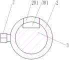
FIG. 2 is a sectional view taken along line A-A in FIG. 1;
fig. 3 is a front view of a measuring rod of the building engineering floor structure dimension detecting device of the present invention;
fig. 4 is a side view of the utility model discloses a building engineering floor structure size detection device's measuring stick.
In the figure: 1. a base plate; 2. a straight pipe; 201. a through hole; 3. a measuring rod; 301. a groove; 4. a cross bar; 5. calibration; 6. a wheel; 7. fixing the bolt; 8. a sponge sleeve.
Detailed Description
To make the objects, technical solutions and advantages of the embodiments of the present invention clearer, the drawings of the embodiments of the present invention are combined to clearly and completely describe the technical solutions of the embodiments of the present invention, and obviously, the described embodiments are some embodiments of the present invention, not all embodiments. Thus, the following detailed description of the embodiments of the present invention, presented in the accompanying drawings, is not intended to limit the scope of the invention, as claimed, but is merely representative of selected embodiments of the invention. Based on the embodiments in the present invention, all other embodiments obtained by a person skilled in the art without creative work belong to the protection scope of the present invention.
In the present invention, unless otherwise expressly stated or limited, the terms "mounted," "connected," and "fixed" are to be construed broadly and may, for example, be fixedly connected, detachably connected, or integrally formed; can be mechanically or electrically connected; either directly or indirectly through intervening media, either internally or in any other relationship. The specific meaning of the above terms in the present invention can be understood according to specific situations by those skilled in the art.
Please refer to fig. 1, fig. 2, fig. 3 and fig. 4, in an embodiment of the present invention, a building engineering floor structure size detection apparatus, including a bottom plate 1, a straight tube 2 is vertically disposed on an upper end surface of the bottom plate 1, a long-strip-shaped through hole 201 is disposed on a side wall of the straight tube 2 along a height direction thereof, a measuring rod 3 is disposed in the straight tube 2, the measuring rod 3 is slidably connected with the straight tube 2, a cross rod 4 is perpendicularly connected to a lower end side wall of the measuring rod 3, a threaded hole is disposed on the lower end side wall of the measuring rod 3, a threaded structure is disposed on an outer wall of one end of the cross rod 4 connected with the measuring rod 3, the cross rod 4 is threadedly connected with the measuring rod 3, the other end of the cross rod 4 passes through the through hole 201 to be located.
The utility model discloses a theory of operation: the utility model discloses a height of the top of straight tube 2 apart from 1 lower extreme of bottom plate is fixed, establishes it to be h1, and scale 5 on the measuring stick 3 can set up like this, and the upper end of scale 5 extends to the upper end of measuring stick 3, and the scale interval of the 5 upper ends of scale is 0. Use the utility model discloses during the measurement, place bottom plate 1 on the bottom of floor, drive measuring stick 3 upward movement through horizontal pole 4 for the top of measuring stick 3 contacts the top of floor, reads the scale interval that scale 5 is located 2 tops of straight tube department, establishes this value as h2, and then the floor height value of here is h1+ h 2.
It is thus clear that, compare with prior art, use the utility model discloses can be very convenient carry out the measurement of floor height, measuring result is more accurate moreover.
Referring to fig. 1, in the embodiment of the present invention, a bottom plate 1 is a rectangular plate, and four corners of the lower end of the bottom plate 1 are respectively provided with a wheel 6; the setting of wheel 6 makes the utility model discloses it is more convenient and laborsaving to remove, has made things convenient for the utility model discloses a use. Assuming that the height of the wheels 6 is h3, the floor height values measured are h1+ h2+ h 3.
Referring to fig. 1 and 2, in the embodiment of the present invention, a threaded through hole is formed on a side wall of an upper end of the straight pipe 2 and communicates with the inside of the straight pipe, and a fixing bolt 7 is disposed in the threaded through hole. When the cross rod 4 drives the measuring rod 3 to move upwards to the upper end of the measuring rod 3 to contact the top of the floor, the fixing bolt 7 is screwed down firstly, and then the scale 5 is read according to the scale value at the top of the straight pipe 2, so that the reading result is more accurate, and the fact that one person can measure the scale value can be guaranteed.
Referring to fig. 1, fig. 2 and fig. 3, in an embodiment of the present invention, a groove 301 is disposed on a sidewall of the measuring rod 3, the groove 301 is disposed along a height direction of the measuring rod 3, and the scale 5 is disposed on a groove wall of the groove 301. With this arrangement, the scale 5 can be effectively prevented from being polished for a long time to fail to correctly read the scale value.
Referring to fig. 4, in the embodiment of the present invention, a sponge sleeve 8 is wrapped on a rod wall of one end of the cross rod 4 located outside the straight tube 2, the sponge sleeve 8 is adhered to the cross rod 4, and the outer wall of the sponge sleeve 8 is provided with anti-slip lines. The arrangement of the sponge sleeve 8 makes the use of the cross rod 4 more comfortable, and the hands cannot be worn out or bubbles cannot be worn out under the long-time continuous use.
The above is only a preferred embodiment of the present invention, and is not intended to limit the present invention, and various modifications and changes will occur to those skilled in the art. Any modification, equivalent replacement, or improvement made within the spirit and principle of the present invention should be included in the protection scope of the present invention.
Claims (6)
1. The utility model provides a building engineering floor structure size detection device, its characterized in that, includes bottom plate (1), vertically on the up end of bottom plate (1) be provided with straight tube (2), be provided with rectangular form through-hole (201) along its direction of height on the lateral wall of straight tube (2), be provided with measuring stick (3) in straight tube (2), measuring stick (3) slide with straight tube (2) and link to each other, be connected with horizontal pole (4) on the lower extreme lateral wall of measuring stick (3) perpendicularly, the one end of horizontal pole (4) links to each other with measuring stick (3), and the other end passes through-hole (201) and is located the outside of straight tube (2), be provided with scale (5) along its direction of height on the lateral wall of measuring stick (3).
2. The building engineering floor structure size detection device of claim 1, characterized in that the bottom plate (1) is a rectangular plate, and the four corners of the lower end of the bottom plate (1) are respectively provided with a wheel (6).
3. The building engineering floor structure size detection device according to claim 1, characterized in that the upper end side wall of the straight pipe (2) is provided with a threaded through hole communicated with the inside of the straight pipe, and the threaded through hole is provided with a fixing bolt (7).
4. The building engineering floor structure size detection device as claimed in claim 1, wherein the side wall of the measuring rod (3) is provided with a groove (301), the groove (301) is arranged along the height direction of the measuring rod (3), and the scale (5) is arranged on the groove wall of the groove (301).
5. The building engineering floor structure size detection device as claimed in any one of claims 1-4, characterized in that the measuring rod (3) is provided with a threaded hole on the lower end side wall, the cross bar (4) is provided with a threaded structure on the outer wall of the end connected with the measuring rod (3), and the cross bar (4) is in threaded connection with the measuring rod (3).
6. The building engineering floor structure size detection device according to any one of claims 1-4, characterized in that a sponge sleeve (8) is wrapped on the rod wall of one end of the cross rod (4) located at the outer side of the straight tube (2), the sponge sleeve (8) is adhered to the cross rod (4), and anti-skid lines are arranged on the outer wall of the sponge sleeve (8).
Priority Applications (1)
| Application Number | Priority Date | Filing Date | Title |
|---|---|---|---|
| CN202020018235.4U CN210862469U (en) | 2020-01-06 | 2020-01-06 | Building engineering floor structure size detection device |
Applications Claiming Priority (1)
| Application Number | Priority Date | Filing Date | Title |
|---|---|---|---|
| CN202020018235.4U CN210862469U (en) | 2020-01-06 | 2020-01-06 | Building engineering floor structure size detection device |
Publications (1)
| Publication Number | Publication Date |
|---|---|
| CN210862469U true CN210862469U (en) | 2020-06-26 |
Family
ID=71293543
Family Applications (1)
| Application Number | Title | Priority Date | Filing Date |
|---|---|---|---|
| CN202020018235.4U Expired - Fee Related CN210862469U (en) | 2020-01-06 | 2020-01-06 | Building engineering floor structure size detection device |
Country Status (1)
| Country | Link |
|---|---|
| CN (1) | CN210862469U (en) |
-
2020
- 2020-01-06 CN CN202020018235.4U patent/CN210862469U/en not_active Expired - Fee Related
Similar Documents
| Publication | Publication Date | Title |
|---|---|---|
| CN215524539U (en) | Wall flatness detection device for construction | |
| CN203785611U (en) | Measuring tool for steel member surface flatness | |
| CN210862469U (en) | Building engineering floor structure size detection device | |
| CN201800391U (en) | Ruler type compasses | |
| CN218847198U (en) | Building engineering is with straightness detection device that hangs down | |
| CN201561726U (en) | Arc diameter measurer | |
| CN201795769U (en) | Tool for measuring strip steel unevenness | |
| CN215714310U (en) | Track scale for track traffic | |
| CN211717368U (en) | Levelness detection device for real estate quality inspection | |
| CN209485240U (en) | Measuring device | |
| CN102338607A (en) | Special instrument for detecting cylinder height | |
| CN210570628U (en) | Land surveying and mapping elevation tool with leveling function | |
| CN217083627U (en) | Building ground flatness detection device | |
| CN207540521U (en) | Railroad track gage measurement instrument | |
| CN202195812U (en) | Slope measuring ruler | |
| CN218155850U (en) | Ruler for measuring irregular bottom surface | |
| CN210689609U (en) | Detection device for building engineering | |
| CN201945263U (en) | Scale with functions of gradienter | |
| CN210570635U (en) | Device for measuring transverse and longitudinal gradient | |
| CN211651407U (en) | Multifunctional caliper | |
| CN203024776U (en) | Multifunctional level gauge | |
| CN212931226U (en) | Vehicle axle axial dimension measuring instrument | |
| CN213902194U (en) | Distance measuring ruler for elevator inspection | |
| CN219532061U (en) | Measuring ruler | |
| CN213238726U (en) | Adjustable depth measuring tool |
Legal Events
| Date | Code | Title | Description |
|---|---|---|---|
| GR01 | Patent grant | ||
| GR01 | Patent grant | ||
| CF01 | Termination of patent right due to non-payment of annual fee | ||
| CF01 | Termination of patent right due to non-payment of annual fee |
Granted publication date: 20200626 Termination date: 20210106 |