CN210850737U - Precast beam quick detach type line production steel form - Google Patents
Precast beam quick detach type line production steel form Download PDFInfo
- Publication number
- CN210850737U CN210850737U CN201921346850.1U CN201921346850U CN210850737U CN 210850737 U CN210850737 U CN 210850737U CN 201921346850 U CN201921346850 U CN 201921346850U CN 210850737 U CN210850737 U CN 210850737U
- Authority
- CN
- China
- Prior art keywords
- steel
- formwork
- prefabricated beam
- prefabricated
- block
- Prior art date
- Legal status (The legal status is an assumption and is not a legal conclusion. Google has not performed a legal analysis and makes no representation as to the accuracy of the status listed.)
- Expired - Fee Related
Links
Images


Landscapes
- Moulds, Cores, Or Mandrels (AREA)
Abstract
本实用新型公开一种预制梁快拆型流水作业钢模板,包括镜像分布的纵向滑移机构,所述纵向滑移机构上方一侧均设有横向滑移机构,横向滑移机构上均设有竖向升降机构,竖向升降机构上均设有预制梁模板支撑钢架,镜像分布的预制梁模板支撑钢架上共同设有精轧螺纹钢对拉杆,镜像分布的纵向滑移机构、横向滑移机构、竖向升降机构与预制梁模板支撑钢架之间设有预制梁。本实用新型预制梁快拆型流水作业钢模板的整个模板安拆工序全部采用常规电动机械化,节省大量人工的同时极大的提高了生产效率及安全性,同时单套模板即可满足一条通长导轨的全部台座的模板需求,节省模板的购置成本,模板整体性好,开始施工后无需重复拆装,施工工序紧凑、快速。
The utility model discloses a prefabricated beam quick dismantling type assembly-flow steel formwork, comprising longitudinal sliding mechanisms distributed in mirror images. The vertical lifting mechanism is equipped with a prefabricated beam formwork support steel frame. The mirrored prefabricated beam formwork support steel frame is provided with a pair of tie rods of fine-rolled rebar, a mirrored longitudinal sliding mechanism and a horizontal sliding mechanism. A prefabricated beam is arranged between the shifting mechanism, the vertical lifting mechanism and the prefabricated beam formwork supporting steel frame. The entire formwork installation and dismantling process of the prefabricated beam quick-release steel formwork of the utility model adopts conventional electric mechanization, which saves a lot of labor and greatly improves the production efficiency and safety. The formwork requirements of all the pedestals of the guide rail save the purchase cost of the formwork, the formwork integrity is good, there is no need to repeat disassembly and assembly after the start of construction, and the construction process is compact and fast.
Description
技术领域technical field
本实用新型涉及一种施工用具领域,具体是一种预制梁快拆型流水作业钢模板。The utility model relates to the field of construction tools, in particular to a prefabricated beam quick-release steel formwork for flow operation.
背景技术Background technique
预制梁,是采用工厂预制,再运至施工现场按设计要求位置进行安装固定的梁,制梁场从建成投入使用到所有箱梁制造、运输、架设完毕一年多的时间,为保证箱梁质量,保证火车在箱梁上安全高速通过,制作箱梁所用的钢筋、水泥、砂子等原料,都有严格的质量要求,目前预制梁模板大部分为龙门吊配合人工组装关、合模板,而关、合的过程需要大量人力并占用机械,同时耗费时间较长。而不断的拆装,对模板本身的使用寿命也有较大影响,尤其是拼接处的闭合,针对这种情况,现提出一种预制梁快拆型流水作业钢模板。Prefabricated beams are beams that are prefabricated in the factory and then transported to the construction site for installation and fixing according to the design requirements. It takes more than one year from the completion of the beam-making yard to the completion of the manufacture, transportation and erection of all box beams. In order to ensure the box beams Quality, to ensure the safe and high-speed passage of trains on the box beams, the steel bars, cement, sand and other raw materials used in the production of box beams have strict quality requirements. , The process of closing requires a lot of manpower and occupies machinery, and takes a long time at the same time. The continuous disassembly and assembly also has a great impact on the service life of the formwork itself, especially the closure of the splices. In view of this situation, a prefabricated beam quick-release steel formwork is proposed.
实用新型内容Utility model content
本实用新型的目的在于提供一种预制梁快拆型流水作业钢模板,改变传统预制梁采用拼装式模板观念,首先将预制梁外模改装为通过底部转轴整体旋转进行拆合模的机械化模板,再将外模模板体系坐落于可纵向滑移的轨道梁车上,梁车上配备具有横向滚动功能的传送带,传送带与外模体系底部进行固接,实现预制梁侧模横向移动,快速机械闭合模板;通过设置纵向导轨快速滑移至下道预制台座,最终仅一套预制流水化模板即可满足整条纵向台座的预制需求,且全部机械化,通过改造侧模和增加轨道、电轮,整套费用低,生产效率高,实现机械化。The purpose of this utility model is to provide a kind of prefabricated beam quick dismantling type flow operation steel formwork, change the traditional prefabricated beam to adopt the assembling type formwork concept, firstly refit the prefabricated beam outer formwork into the mechanized formwork which disassembles and assembles the formwork through the integral rotation of the bottom shaft, and then The outer mold formwork system is located on the rail beam car that can slide longitudinally. The beam car is equipped with a conveyor belt with lateral rolling function. The conveyor belt is fixed to the bottom of the outer mold system to realize the lateral movement of the prefabricated beam side mold and the rapid mechanical closing of the formwork; By setting longitudinal guide rails to quickly slide to the next prefabricated pedestal, finally only one set of prefabricated flow template can meet the prefabrication requirements of the entire longitudinal pedestal, and all of them are mechanized. By modifying the side molds and adding tracks and electric wheels, the cost of the whole set is low. , high production efficiency and mechanization.
本实用新型的目的可以通过以下技术方案实现:The purpose of the present utility model can be achieved through the following technical solutions:
一种预制梁快拆型流水作业钢模板,包括镜像分布的纵向滑移机构,所述纵向滑移机构上方一侧均设有横向滑移机构,横向滑移机构上均设有竖向升降机构,竖向升降机构上均设有预制梁模板支撑钢架,镜像分布的预制梁模板支撑钢架上共同设有精轧螺纹钢对拉杆,镜像分布的纵向滑移机构、横向滑移机构、竖向升降机构与预制梁模板支撑钢架之间设有预制梁。A prefabricated beam quick-release steel formwork for assembly line operation includes longitudinal sliding mechanisms distributed in mirror images, a lateral sliding mechanism is provided on one side above the longitudinal sliding mechanism, and a vertical lifting mechanism is provided on the transverse sliding mechanism. , The vertical lifting mechanism is equipped with a prefabricated beam formwork support steel frame, and the mirror-distributed prefabricated beam formwork support steel frame is provided with a fine-rolled steel tie rod, and the mirror-distributed longitudinal sliding mechanism, lateral sliding mechanism, vertical A prefabricated beam is arranged between the lifting mechanism and the prefabricated beam formwork supporting steel frame.
进一步地,所述预制梁模板支撑钢架内还设有第一外辅助支撑钢板、第二外辅助支撑钢板与第三外辅助支撑钢板。Further, the prefabricated beam formwork supporting steel frame is further provided with a first outer auxiliary supporting steel plate, a second outer auxiliary supporting steel plate and a third outer auxiliary supporting steel plate.
进一步地,所述预制梁内还设有轴向阵列分布的第一内辅助钢板,第一内辅助钢板之间设有第二内辅助钢板,第一内辅助钢板之间还设有斜辅助支撑钢板,第一内辅助钢板内还设有第三内辅助钢板。Further, the prefabricated beam is also provided with first inner auxiliary steel plates distributed in an axial array, a second inner auxiliary steel plate is arranged between the first inner auxiliary steel plates, and an oblique auxiliary support is also arranged between the first inner auxiliary steel plates. The first inner auxiliary steel plate is further provided with a third inner auxiliary steel plate.
进一步地,所述纵向滑移机构包括阵列分布的底部工字钢,底部工字钢上均设有支撑块,支撑块之间设有支撑工字钢,支撑块上共同设有第一工字钢,第一工字钢一侧设有与支撑块连接的斜支撑块,第一工字钢上一端设有第一液压缸固定块,第一液压缸固定块上设有第一液压缸固定孔,第一液压缸固定块上设有第一液压缸,第一液压缸上设有第一伸缩杆,第一伸缩杆顶端设有第一连接头,第一连接头,第一连接头上设有第一安装孔。Further, the longitudinal sliding mechanism includes bottom I-beams distributed in an array, and support blocks are arranged on the bottom I-beams, and support I-beams are arranged between the support blocks, and the first I-beams are jointly arranged on the support blocks. Steel, one side of the first I-beam is provided with an oblique support block connected to the support block, the upper end of the first I-beam is provided with a first hydraulic cylinder fixing block, and the first hydraulic cylinder fixing block is provided with a first hydraulic cylinder fixing block The first hydraulic cylinder fixing block is provided with a first hydraulic cylinder, the first hydraulic cylinder is provided with a first telescopic rod, the top of the first telescopic rod is provided with a first connecting head, the first connecting head, on the first connecting head A first mounting hole is provided.
进一步地,所述横向滑移机构包括第一固定板,第一固定板下端设有第一滑块,第一滑块上设有伸缩杆槽,第一固定板下端还设有第二连接头,第二连接头上设有第二安装孔,第一固定板上端设有阵列分布的上支撑块,上支撑块上共同设有第二固定板。Further, the lateral sliding mechanism includes a first fixing plate, the lower end of the first fixing plate is provided with a first sliding block, the first sliding block is provided with a telescopic rod slot, and the lower end of the first fixing plate is also provided with a second connecting head. The second connecting head is provided with a second mounting hole, the upper end of the first fixing plate is provided with an array of upper support blocks, and the upper support blocks are jointly provided with a second fixing plate.
进一步地,所述竖向升降机构包括固定在第二固定板上的第三固定板,第三固定板上设有阵列分布的第二液压缸,第二液压缸上设有第二伸缩杆,第二伸缩杆上设有第三连接头,第三连接头连接第四连接头,第三连接头上设有第三安装孔,第四连接头上设有第四安装孔,第四连接头上还设有连接平台,连接平台上均设有第二工字钢,第二工字钢之间共同设有第三工字钢。Further, the vertical lifting mechanism includes a third fixing plate fixed on the second fixing plate, the third fixing plate is provided with second hydraulic cylinders distributed in an array, and the second hydraulic cylinder is provided with a second telescopic rod, The second telescopic rod is provided with a third connector, the third connector is connected to the fourth connector, the third connector is provided with a third mounting hole, the fourth connector is provided with a fourth mounting hole, and the fourth connector A connection platform is also provided on the connection platform, and second I-beams are arranged on the connection platforms, and a third I-beam is jointly arranged between the second I-beams.
进一步地,所述预制梁模板支撑钢架包括竖向设置的第四工字钢,第四工字钢一侧设有配重块,配重块通过连接块固定在第四工字钢上,第四工字钢一侧设有第五工字钢,第五工字钢上设有第六工字钢,第六工字钢上设有第七工字钢,第七工字钢上设有斜支撑钢架,第七工字钢上还设有角钢。Further, the prefabricated beam formwork supporting steel frame includes a fourth I-beam vertically arranged, and a counterweight block is provided on one side of the fourth I-beam, and the counterweight block is fixed on the fourth I-beam through a connecting block, A fifth I-beam is arranged on one side of the fourth I-beam, a sixth I-beam is arranged on the fifth I-beam, a seventh I-beam is arranged on the sixth I-beam, and a seventh I-beam is arranged on the seventh I-beam. There is an inclined support steel frame, and an angle steel is also provided on the seventh I-beam.
进一步地,所述斜支撑钢架包括阵列分布的短工字钢,短工字钢上均设有阵列分布的连接孔,短工字钢之间通过连接孔连接钢丝连接,其中两个短工字钢之间还设有斜工字钢,其中一个短工字钢上还设有斜支撑块,斜工字钢下端设有支撑钢块。Further, the oblique support steel frame includes short I-beams distributed in an array, and the short I-beams are all provided with connection holes distributed in an array, and the short I-beams are connected by connecting steel wires through the connecting holes, wherein the two short I-beams are connected between The oblique I-beam is also provided, one of the short I-beams is also provided with an oblique support block, and the lower end of the oblique I-beam is provided with a support steel block.
进一步地,所述精轧螺纹钢对拉杆包括钢筋,钢筋两端均设有螺纹端,螺纹端上设有防滑垫片与螺母。Further, the finish-rolled threaded steel pair tie rod includes steel bars, both ends of the steel bars are provided with threaded ends, and the threaded ends are provided with anti-skid gaskets and nuts.
进一步地,所述预制梁包括预制梁体,预制梁体下端设有阵列分布的底部放置钢块,钢块固定在支撑基台上,支撑基台固定在高强度水泥地面上。Further, the prefabricated beam includes a prefabricated beam body, the lower end of the prefabricated beam body is provided with an array of bottom placement steel blocks, the steel blocks are fixed on a support base, and the support base is fixed on a high-strength cement floor.
本实用新型的有益效果:The beneficial effects of the present utility model:
1、本实用新型为预制梁快拆型流水作业钢模板,安拆模过程快速机械化;通过改造侧模和增加轨道、电轮,整套费用低,生产效率高;1. The utility model is a prefabricated beam quick-release steel formwork for flow operation, and the process of installing and removing the formwork is quickly mechanized; by transforming the side formwork and adding rails and electric wheels, the cost of the whole set is low and the production efficiency is high;
2、本实用新型预制梁快拆型流水作业钢模板采用底部旋转闭合模板的方式,无需龙门吊装配合人工进行复杂的脱模工序;2. The prefabricated beam quick-release steel formwork of the present utility model adopts the method of bottom rotating closed formwork, which does not require gantry hoisting and manual complicated demoulding process;
3、本实用新型预制梁快拆型流水作业钢模板采用横向传送带机械化脱离预制好的梁片,过程安全、迅捷;3. The prefabricated beam quick-release steel formwork of the present utility model adopts the transverse conveyor belt to mechanically separate from the prefabricated beams, and the process is safe and fast;
4、本实用新型预制梁快拆型流水作业钢模板使用纵向导轨进行纵向通长的滑移,预制台座的转换极为方便、迅速;4. The prefabricated beam quick-release steel formwork of the present utility model uses longitudinal guide rails for longitudinal sliding, and the conversion of the prefabricated pedestal is extremely convenient and rapid;
5、本实用新型预制梁快拆型流水作业钢模板的整个模板安拆工序全部采用常规电动机械化,节省大量人工的同时极大的提高了生产效率及安全性,同时单套模板即可满足一条通长导轨的全部台座的模板需求,节省模板的购置成本;5. The entire formwork installation and dismantling process of the prefabricated beam quick-release steel formwork of the present utility model adopts conventional electric mechanization, which saves a lot of labor and greatly improves the production efficiency and safety. At the same time, a single set of formwork can satisfy one The template requirements of all the pedestals of the full-length guide rail save the purchase cost of the template;
6、本实用新型模板整体性好,开始施工后无需重复拆装,施工工序紧凑、快速,且过程机械化几乎不需要人工,生产效率极高。6. The formwork of the utility model has good integrity, and does not need to be disassembled and assembled repeatedly after starting construction. The construction process is compact and fast, and the mechanization of the process requires almost no labor, and the production efficiency is extremely high.
附图说明Description of drawings
下面结合附图对本实用新型作进一步的说明。The utility model will be further described below in conjunction with the accompanying drawings.
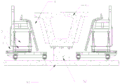
图1是本实用新型预制梁快拆型流水作业钢模板部分结构示意图;Fig. 1 is the prefabricated beam quick dismantling type flow operation steel formwork part structural representation of the present utility model;
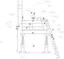
图2是本实用新型预制梁快拆型流水作业钢模板部分结构示意图;Fig. 2 is the structural schematic diagram of part of the prefabricated beam quick dismantling type flow operation steel formwork of the present utility model;
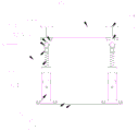
图3是本实用新型预制梁快拆型流水作业钢模板部分示意图;Fig. 3 is the partial schematic diagram of the prefabricated beam quick dismantling type flow operation steel formwork of the present utility model;
图4是本实用新型预制梁模板支撑钢架结构示意图;4 is a schematic diagram of the prefabricated beam formwork supporting steel frame structure of the present invention;
图5是本实用新型纵向滑移机构结构示意图;Fig. 5 is the structural schematic diagram of the longitudinal sliding mechanism of the present utility model;
图6是本实用新型竖向升降机构结构示意图。FIG. 6 is a schematic structural diagram of the vertical lifting mechanism of the present invention.
具体实施方式Detailed ways
下面将结合本实用新型实施例中的附图,对本实用新型实施例中的技术方案进行清楚、完整地描述,显然,所描述的实施例仅仅是本实用新型一部分实施例,而不是全部的实施例。基于本实用新型中的实施例,本领域普通技术人员在没有作出创造性劳动前提下所获得的所有其它实施例,都属于本实用新型保护的范围。The technical solutions in the embodiments of the present utility model will be clearly and completely described below with reference to the accompanying drawings in the embodiments of the present utility model. Obviously, the described embodiments are only a part of the embodiments of the present utility model, rather than all the implementations. example. Based on the embodiments of the present invention, all other embodiments obtained by those of ordinary skill in the art without creative work fall within the protection scope of the present invention.
在本实用新型的描述中,需要理解的是,术语“开孔”、“上”、“下”、“厚度”、“顶”、“中”、“长度”、“内”、“四周”等指示方位或位置关系,仅是为了便于描述本实用新型和简化描述,而不是指示或暗示所指的组件或元件必须具有特定的方位,以特定的方位构造和操作,因此不能理解为对本实用新型的限制。In the description of the present invention, it should be understood that the terms "opening", "upper", "lower", "thickness", "top", "middle", "length", "inside", "surrounding" It is only for the convenience of describing the present utility model and simplifying the description, rather than indicating or implying that the components or elements referred to must have a specific orientation, are constructed and operated in a specific orientation, and therefore cannot be understood as a reference to the present utility model. New type of restriction.
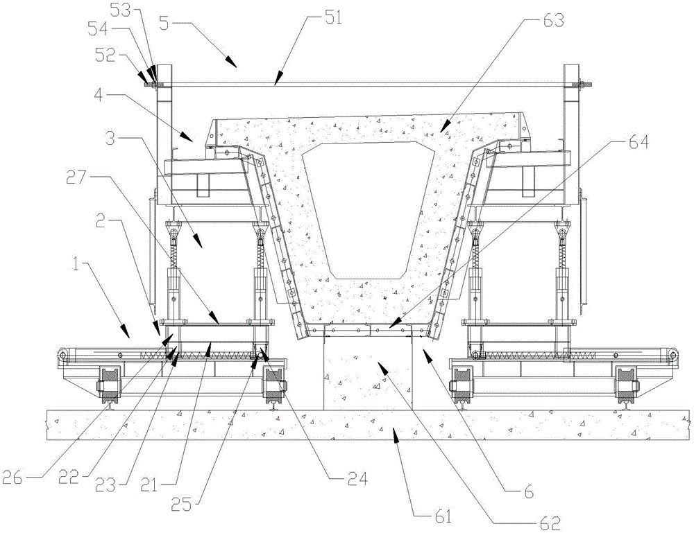
一种预制梁快拆型流水作业钢模板,包括镜像分布的纵向滑移机构1,如图1、图2、图3所示,纵向滑移机构1上方一侧均设有横向滑移机构2,横向滑移机构2上均设有竖向升降机构3,竖向升降机构3上均设有预制梁模板支撑钢架4,镜像分布的预制梁模板支撑钢架4上共同设有精轧螺纹钢对拉杆5,镜像分布的纵向滑移机构1、横向滑移机构2、竖向升降机构3与预制梁模板支撑钢架4之间设有预制梁6。A prefabricated beam quick-release steel formwork for assembly line operation includes a
预制梁模板支撑钢架4内还设有第一外辅助支撑钢板7、第二外辅助支撑钢板71与第三外辅助支撑钢板72。The prefabricated beam formwork supporting
预制梁6内还设有轴向阵列分布的第一内辅助钢板8,如图2所示,第一内辅助钢板8之间设有第二内辅助钢板81,第一内辅助钢板8之间还设有斜辅助支撑钢板82,第一内辅助钢板8内还设有第三内辅助钢板83。The prefabricated beam 6 is also provided with first inner auxiliary steel plates 8 distributed in an axial array. As shown in FIG. 2 , a second inner
纵向滑移机构1包括阵列分布的底部工字钢11,如图5所示,底部工字钢11上均设有支撑块111,支撑块111之间设有支撑工字钢112,支撑块111上共同设有第一工字钢12,第一工字钢12一侧设有与支撑块111连接的斜支撑块13,第一工字钢12上一端设有第一液压缸固定块14,第一液压缸固定块14上设有第一液压缸固定孔141,第一液压缸固定块14上设有第一液压缸15,第一液压缸15上设有第一伸缩杆151,第一伸缩杆151顶端设有第一连接头152,第一连接头152,第一连接头152上设有第一安装孔153。The longitudinal sliding
横向滑移机构2包括第一固定板21,如图1所示,第一固定板21下端设有第一滑块22,第一滑块22上设有伸缩杆槽23,第一固定板21下端还设有第二连接头24,第二连接头24上设有第二安装孔25,第一固定板21上端设有阵列分布的上支撑块26,上支撑块26上共同设有第二固定板27。The lateral sliding mechanism 2 includes a
竖向升降机构3包括固定在第二固定板27上的第三固定板31,如图6所示,第三固定板31上设有阵列分布的第二液压缸32,第二液压缸32上设有第二伸缩杆321,第二伸缩杆321上设有第三连接头322,第三连接头322连接第四连接头33,第三连接头322上设有第三安装孔323,第四连接头33上设有第四安装孔331,第四连接头33上还设有连接平台332,连接平台332上均设有第二工字钢34,第二工字钢34之间共同设有第三工字钢35。The
预制梁模板支撑钢架4包括竖向设置的第四工字钢41,如图4所示,第四工字钢41一侧设有配重块42,配重块42通过连接块421固定在第四工字钢41上,第四工字钢41一侧设有第五工字钢43,第五工字钢43上设有第六工字钢44,第六工字钢44上设有第七工字钢441,第七工字钢441上设有斜支撑钢架45,第七工字钢441上还设有角钢442。The prefabricated beam formwork
斜支撑钢架45包括阵列分布的短工字钢451,如图4所示,短工字钢451上均设有阵列分布的连接孔453,短工字钢451之间通过连接孔453连接钢丝连接,其中两个短工字钢451之间还设有斜工字钢454,其中一个短工字钢451上还设有斜支撑块456,斜工字钢454下端设有支撑钢块457。The inclined
精轧螺纹钢对拉杆5包括钢筋51,如图1所示,钢筋51两端均设有螺纹端52,螺纹端52上设有防滑垫片53与螺母54。The finish-rolled threaded steel pair tie rod 5 includes a steel bar 51. As shown in FIG. 1, both ends of the steel bar 51 are provided with threaded ends 52, and the threaded ends 52 are provided with anti-skid gaskets 53 and nuts 54.
预制梁6包括预制梁体63,如图1所示,预制梁体63下端设有阵列分布的底部放置钢块64,钢块64固定在支撑基台62上,支撑基台62固定在高强度水泥地面61上。The prefabricated beam 6 includes a
使用时,拼装纵向滑移机构1、横向滑移机构2与竖向升降机构3,焊接预制梁模板支撑钢架4,施拼装纵向滑移机构1在横向滑移机构2,横向滑移机构2在竖向升降机构3,就位到合模浇筑位置,通过精轧螺纹钢对拉杆5使模板对拉固定,进行混凝土浇筑,浇筑完成后,逆序拆模,将整个模板系统通过纵向滑移机构1下一台座,重复上述步骤进行下一台座上的预制梁浇筑。When in use, assemble the longitudinal sliding
在本说明书的描述中,参考术语“一个实施例”、“示例”、“具体示例”等的描述意指结合该实施例或示例描述的具体特征、结构、材料或者特点包含于本实用新型的至少一个实施例或示例中。在本说明书中,对上述术语的示意性表述不一定指的是相同的实施例或示例。而且,描述的具体特征、结构、材料或者特点可以在任何的一个或多个实施例或示例中以合适的方式结合。In the description of this specification, description with reference to the terms "one embodiment", "example", "specific example", etc. means that a specific feature, structure, material or characteristic described in connection with the embodiment or example is included in the present invention. in at least one embodiment or example. In this specification, schematic representations of the above terms do not necessarily refer to the same embodiment or example. Furthermore, the particular features, structures, materials or characteristics described may be combined in any suitable manner in any one or more embodiments or examples.
以上显示和描述了本实用新型的基本原理、主要特征和本实用新型的优点。本行业的技术人员应该了解,本实用新型不受上述实施例的限制,上述实施例和说明书中描述的只是说明本实用新型的原理,在不脱离本实用新型精神和范围的前提下,本实用新型还会有各种变化和改进,这些变化和改进都落入要求保护的本实用新型范围内。The basic principles, main features and advantages of the present invention have been shown and described above. It should be understood by those skilled in the art that the present invention is not limited by the above-mentioned embodiments. The above-mentioned embodiments and descriptions only illustrate the principle of the present invention. Without departing from the spirit and scope of the present invention, the present invention There will also be various changes and improvements in the new model, which all fall within the scope of the claimed invention.
Claims (10)
Priority Applications (1)
| Application Number | Priority Date | Filing Date | Title |
|---|---|---|---|
| CN201921346850.1U CN210850737U (en) | 2019-08-19 | 2019-08-19 | Precast beam quick detach type line production steel form |
Applications Claiming Priority (1)
| Application Number | Priority Date | Filing Date | Title |
|---|---|---|---|
| CN201921346850.1U CN210850737U (en) | 2019-08-19 | 2019-08-19 | Precast beam quick detach type line production steel form |
Publications (1)
| Publication Number | Publication Date |
|---|---|
| CN210850737U true CN210850737U (en) | 2020-06-26 |
Family
ID=71296402
Family Applications (1)
| Application Number | Title | Priority Date | Filing Date |
|---|---|---|---|
| CN201921346850.1U Expired - Fee Related CN210850737U (en) | 2019-08-19 | 2019-08-19 | Precast beam quick detach type line production steel form |
Country Status (1)
| Country | Link |
|---|---|
| CN (1) | CN210850737U (en) |
Cited By (1)
| Publication number | Priority date | Publication date | Assignee | Title |
|---|---|---|---|---|
| CN110394886A (en) * | 2019-08-19 | 2019-11-01 | 中交一公局第四工程有限公司 | A kind of precast beam type quick detaching continuous productive process steel form |
-
2019
- 2019-08-19 CN CN201921346850.1U patent/CN210850737U/en not_active Expired - Fee Related
Cited By (1)
| Publication number | Priority date | Publication date | Assignee | Title |
|---|---|---|---|---|
| CN110394886A (en) * | 2019-08-19 | 2019-11-01 | 中交一公局第四工程有限公司 | A kind of precast beam type quick detaching continuous productive process steel form |
Similar Documents
| Publication | Publication Date | Title |
|---|---|---|
| CN108580758B (en) | Double-layer steel mesh processing device | |
| CN103161126A (en) | Road bridge variable section hollow high pier slip-form construction method | |
| CN110847050B (en) | Large-span prefabricated corrugated steel web composite beam top and bottom plate synchronous pouring template and application method thereof | |
| CN106089253A (en) | A fully hydraulic formwork system for culvert pouring | |
| CN110878522B (en) | Construction system and construction method of beam under main tower | |
| CN103452350B (en) | Assembling electronic workshop and construction method thereof | |
| CN112681162A (en) | Construction method for movable split mounting type light formwork cast-in-situ box culvert | |
| CN114517575A (en) | Formwork-attached assembling type double-layer integral hoisting elevator shaft construction method | |
| CN115418983B (en) | Construction method of prefabricated box culverts in large-section shield tunnels jointly built by highway and railway | |
| CN104695335A (en) | Overall reinforcement binding and hoisting construction method and construction device adopting upstroke movable scaffolding | |
| CN114033234A (en) | Novel main tower crown structure and sectional installation method thereof | |
| CN204982681U (en) | Steel bow member integral translation device | |
| CN210850737U (en) | Precast beam quick detach type line production steel form | |
| CN110394886A (en) | A kind of precast beam type quick detaching continuous productive process steel form | |
| CN204919605U (en) | Prefabricated assembled reinforced concrete utility tunnel and production mould thereof | |
| CN104924419B (en) | Automatic template opening/closing system for construction of large-volume precast concrete component | |
| CN107829408B (en) | Rectangular aqueduct construction steel mould trolley | |
| CN203603542U (en) | Fabricated electronic workshop | |
| CN112627034A (en) | Synchronous construction method for turning over mold of high pier of bridge | |
| CN219972937U (en) | Construction assembly type bracket for bottom die of solid section at top of hollow pier | |
| CN118007543A (en) | Pier climbing frame turnover formwork construction device and construction method | |
| CN111140254A (en) | A formwork system and formwork transfer method for long-distance tunnel full-circle double-lined inverted arch construction | |
| CN118375110A (en) | A new type of hydraulically disassembled ship lock chamber wall integral mobile mold machine and construction method | |
| CN114875955B (en) | Ultra-long concrete straight retaining wall template mounting device and construction method thereof | |
| CN112571593A (en) | Combined type steel pedestal module unit structure suitable for different precast beam sizes |
Legal Events
| Date | Code | Title | Description |
|---|---|---|---|
| GR01 | Patent grant | ||
| GR01 | Patent grant | ||
| CF01 | Termination of patent right due to non-payment of annual fee | ||
| CF01 | Termination of patent right due to non-payment of annual fee |
Granted publication date: 20200626 |