CN210848639U - Steel ball blank cutting device for steel ball processing - Google Patents
Steel ball blank cutting device for steel ball processing Download PDFInfo
- Publication number
- CN210848639U CN210848639U CN201922029223.1U CN201922029223U CN210848639U CN 210848639 U CN210848639 U CN 210848639U CN 201922029223 U CN201922029223 U CN 201922029223U CN 210848639 U CN210848639 U CN 210848639U
- Authority
- CN
- China
- Prior art keywords
- steel ball
- mounting
- rack
- gear
- processing
- Prior art date
- Legal status (The legal status is an assumption and is not a legal conclusion. Google has not performed a legal analysis and makes no representation as to the accuracy of the status listed.)
- Active
Links
Images

Abstract
The utility model belongs to the field of steel ball processing, in particular to a steel ball blank cutting device for steel ball processing, aiming at the problems of low cutting efficiency and poor effect of the existing steel ball blank cutting device, the utility model provides a proposal which comprises a mounting rack, a top plate is fixedly arranged at the upper end of the mounting rack, a first air cylinder is fixedly arranged at the upper end of the top plate, a lifting rod is fixedly connected with the output end of the first air cylinder, the lower end of the lifting rod passes through the top plate and extends to the lower part of the top plate, a lifting mounting plate is fixedly arranged at the lower end of the lifting rod, a cutting motor is fixedly arranged at the left end of the lifting mounting plate, a driving shaft is fixedly connected with the output shaft of the cutting motor, the right end of the driving shaft is rotatably connected with the inner side wall of the lifting mounting plate, a cutting wheel is fixedly, cutting efficiency is high, and degree of automation is high, and the practicality is strong.
Description
Technical Field
The utility model relates to a steel ball processing field especially relates to a steel ball base cutting device is used in steel ball processing.
Background
The processing of the wear-resistant steel ball usually includes the processes of cold heading, cutting, polishing, heat treatment, hard grinding, primary grinding, fine grinding and the like, wherein one process is to cut the steel ball raw material into a steel ball blank so as to facilitate the grinding and heat treatment of the steel ball. The moving process of the cutting wheel in the existing steel ball blank cutting device for processing the steel ball is long, so that the cutting efficiency is low, the effect is poor, and the steel ball raw material cannot be well fixed, so that the steel ball blank cutting device for processing the steel ball is provided.
SUMMERY OF THE UTILITY MODEL
The utility model provides a pair of steel ball base cutting device is used in steel ball processing has solved current steel ball base cutting device cutting inefficiency, and the effect is poor, can not carry out fine fixed problem to the steel ball raw materials.
In order to achieve the above purpose, the utility model adopts the following technical scheme:
a steel ball blank cutting device for steel ball processing comprises a mounting frame, wherein a top plate is fixedly mounted at the upper end of the mounting frame, a first air cylinder is fixedly mounted at the upper end of the top plate, a lifting rod is fixedly connected with the output end of the first air cylinder, the lower end of the lifting rod penetrates through the top plate and extends to the position below the top plate, a lifting mounting plate is fixedly mounted at the lower end of the lifting rod, a cutting motor is fixedly mounted at the left end of the lifting mounting plate, a driving shaft is fixedly connected with the output end of the cutting motor, the right end of the driving shaft is rotatably connected with the inner side wall of the lifting mounting plate, a cutting wheel is fixedly sleeved on the driving shaft, a first rotating shaft is rotatably mounted on the mounting frame through a bearing and is positioned on the left side of the first air cylinder, a first gear is fixedly sleeved on the first rotating shaft and is positioned on the rear, the upper end of the first rack penetrates through the top plate and extends to the upper part of the top plate, the first rack is movably connected with the top plate, the left end of the first rack is meshed with the first gear, the bottom end of the inner side of the mounting rack is fixedly provided with two fixing frames and a hollow mounting plate, the two fixing frames are respectively provided with a second gear and a third gear through a second rotating shaft and a mounting shaft in a rotating way, the right end of the second gear is meshed with the third gear, a second rack is arranged inside the hollow mounting plate in a sliding manner in the vertical direction, the right end of the third gear penetrates through the hollow mounting plate to be meshed with the second rack, the upper end of the second rack penetrates through the hollow mounting plate, and extend to hollow mounting panel top, and second rack upper end fixed mounting has the processing platform, processing bench end fixed mounting has two second cylinders, the equal fixed mounting of second cylinder output has splint.
Preferably, the drive shaft is rotatably connected with the lifting mounting plate through a bearing.
Preferably, two splint one end of being close to each other all is provided with anti-skidding line.
Preferably, a first chain wheel is fixedly sleeved on the first rotating shaft, a second chain wheel is fixedly sleeved on the second rotating shaft, and the first chain wheel is connected with the second chain wheel through a chain.
Preferably, a rubber shock pad is fixedly arranged at the bottom end of the mounting frame.
The utility model has the advantages that: the steel ball raw material can be automatically clamped and fixed and is automatically cut by arranging the processing table, the second cylinder, the clamping plate, the cutting motor, the cutting wheel, the driving shaft and the lifting mounting plate; through setting up first cylinder, first rack, dead lever, first pivot, first gear, second gear, mount, second pivot, third gear, hollow mounting panel and second rack, the removal process when the retractable cutting wheel cuts reduces the cutting required time, and then improves cutting efficiency for the cutting progress, the utility model discloses the fixed mounting of being convenient for, cutting efficiency is high, and degree of automation is high, and the practicality is strong.
Drawings
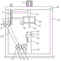
Fig. 1 is a schematic structural diagram of a steel ball blank cutting device for processing a steel ball according to the present invention.
Fig. 2 is a left side partial view of a processing table in the steel ball blank cutting device for processing steel balls provided by the utility model.
Reference numbers in the figures: the cutting machine comprises a first cylinder 1, a first rack 2, a fixing rod 3, a first rotating shaft 4, a first gear 5, a second gear 6, a fixing frame 7, a second rotating shaft 8, a third gear 9, a hollow mounting plate 10, a second rack 11, a machining table 12, a second cylinder 13, a clamping plate 14, a cutting motor 15, a cutting wheel 16, a driving shaft 17, a lifting mounting plate 18, a lifting rod 19, a top plate 20, a mounting frame 21 and a chain 22.
Detailed Description
The technical solutions in the embodiments of the present invention will be described clearly and completely with reference to the accompanying drawings in the embodiments of the present invention, and it is obvious that the described embodiments are only some embodiments of the present invention, not all embodiments.
Referring to fig. 1-2, a steel ball blank cutting device for steel ball processing, includes a mounting bracket 21, a top plate 20 is fixedly mounted on the upper end of the mounting bracket 21, a first cylinder 1 is fixedly mounted on the upper end of the top plate 20, an output end of the first cylinder 1 is fixedly connected with a lifting rod 19, the lower end of the lifting rod 19 penetrates through the top plate 20 and extends to the lower side of the top plate 20, a lifting mounting plate 18 is fixedly mounted on the lower end of the lifting rod 19, a cutting motor 15 is fixedly mounted on the left end of the lifting mounting plate 18, an output shaft of the cutting motor 15 is fixedly connected with a driving shaft 17, the right end of the driving shaft 17 is rotatably connected with the inner side wall of the lifting mounting plate 18, a cutting wheel 16 is fixedly sleeved on the driving shaft 17, a first rotating shaft 4 is rotatably mounted on the mounting bracket 21 through a bearing, and a first, and the first gear 5 is located the rear side of the mounting frame 21, the left ends of the lifting rod 19 and the lifting mounting plate 18 are fixed at the right end of the first rack 2 through the fixing rod 3, the upper end of the first rack 2 passes through the top plate 20 and extends to the upper side of the top plate 20, the first rack 2 is movably connected with the top plate 20, the left end of the first rack 2 is meshed with the first gear 5, two fixing frames 7 and a hollow mounting plate 10 are fixedly mounted at the bottom end of the inner side of the mounting frame 21, a second gear 6 and a third gear 9 are respectively mounted on the two fixing frames 7 through a second rotating shaft 8 and a mounting shaft in a rotating manner, the right end of the second gear 6 is meshed with the third gear 9, the second rack 11 is slidably mounted inside the hollow mounting plate 10 in the vertical direction, the second rack 11 can move up and down in the hollow mounting plate 10, and the right end of the third gear 9 passes through the hollow mounting, hollow mounting panel 10 is passed to 11 upper ends of second rack to extend to hollow mounting panel 10 top, and 11 upper ends fixed mounting of second rack have processing platform 12, processing platform 12 upper end fixed mounting has two second cylinders 13, the equal fixed mounting of second cylinder 13 output has splint 14, through being provided with splint 14, can realize pressing from both sides tightly fixedly to the steel ball raw materials, and then improves cutting effect.
In this embodiment, drive shaft 17 passes through the bearing and is connected with 18 rotations of lift mounting panel, through above-mentioned design, can improve drive shaft 17 and 18 stability of rotating the installation of lift mounting panel, two splint 14 is close to one end each other and all is provided with anti-skidding line, through above-mentioned design, can improve the tight effect of clamp of two splint 14 to the steel ball raw materials, fixed cover is equipped with first sprocket on first pivot 4, fixed cover is equipped with the second sprocket on the second pivot 8, first sprocket is connected with the second sprocket through chain 22, through above-mentioned design, can realize first pivot 4 and 8 linkages of second pivot, and then has improved the utility model discloses degree of automation, 21 bottom mounting of mounting bracket is provided with the rubber shock pad, through being provided with the rubber shock pad, can improve the utility model discloses shock attenuation effect.
The electrical components presented in the document are all electrically connected with an external master controller and 220V mains, and the master controller can be a conventional known device controlled by a computer or the like.
Example (b): putting a steel ball raw material on a processing table 12, putting a position to be cut on the steel ball raw material under a cutting wheel 16, starting two second cylinders 13, wherein the two second cylinders 13 can drive two clamping plates 14 to approach each other when working, so that the two clamping plates 14 clamp and fix the steel ball raw material, then starting a cutting motor 15, the cutting motor 15 drives the cutting wheel 16 to rotate through a driving shaft 17 when working, then starting a first cylinder 1, the first cylinder 1 drives a lifting rod 19 to move downwards, further drives a lifting mounting plate 18 to move downwards, further can drive a first rack 2 to move downwards through a fixing rod 3, the first rack 2 which moves downwards drives a first gear 5 to rotate clockwise, the first gear 5 which rotates clockwise drives a first rotating shaft 4 to rotate clockwise, and the first rotating shaft 4 which rotates clockwise drives a second rotating shaft 8 to rotate clockwise through a first chain wheel, a second chain wheel and a chain 22, and then drive second gear 6 and rotate clockwise, clockwise second gear 6 drives third gear 9 and rotates anticlockwise through gear engagement, and then drive second rack 11 and move up, the second rack 11 that shifts up drives the steel ball raw materials through processing platform 12 and shifts up, and lifter 19 moves down and accessible lift mounting panel 18 drives cutting wheel 16 and moves down, and then can shorten the process that cutting wheel 16 moved down, improve cutting efficiency, when cutting wheel 16 and steel ball raw materials contact, can cut the steel ball raw materials. By arranging the processing table 12, the second air cylinder 13, the clamping plate 14, the cutting motor 15, the cutting wheel 16, the driving shaft 17 and the lifting mounting plate 18, the steel ball raw material can be automatically clamped and fixed, and can be automatically cut; through setting up first cylinder 1, first rack 2, dead lever 3, first pivot 4, first gear 5, second gear 6, mount 7, second pivot 8, third gear 9, hollow mounting panel 10 and second rack 11, the removal process when the cutting wheel 16 cutting can be shortened, reduces the required time of cutting, and then improves cutting efficiency for the cutting progress. The utility model discloses the fixed mounting of being convenient for, the cutting is efficient, and degree of automation is high, and the practicality is strong.
In the description of the present invention, it is to be understood that the terms "center", "longitudinal", "lateral", "length", "width", "thickness", "upper", "lower", "front", "rear", "left", "right", "vertical", "horizontal", "top", "bottom", "inner", "outer", "clockwise", "counterclockwise", and the like indicate orientations or positional relationships based on the orientations or positional relationships shown in the drawings, and are only for convenience of description and to simplify the description, but do not indicate or imply that the device or element referred to must have a particular orientation, be constructed and operated in a particular orientation, and therefore should not be construed as limiting the present invention.
Furthermore, the terms "first", "second" and "first" are used for descriptive purposes only and are not to be construed as indicating or implying relative importance or implicitly indicating the number of technical features indicated. Thus, a feature defined as "first" or "second" may explicitly or implicitly include one or more of that feature. In the description of the present invention, "a plurality" means two or more unless specifically limited otherwise.
The above, only be the concrete implementation of the preferred embodiment of the present invention, but the protection scope of the present invention is not limited thereto, and any person skilled in the art is in the technical scope of the present invention, according to the technical solution of the present invention and the utility model, the concept of which is equivalent to replace or change, should be covered within the protection scope of the present invention.
Claims (5)
1. The utility model provides a steel ball base cutting device is used in steel ball processing, includes mounting bracket (21), its characterized in that, mounting bracket (21) upper end fixed mounting has roof (20), roof (20) upper end fixed mounting has first cylinder (1), first cylinder (1) output end fixed connection has lifter (19), lifter (19) lower extreme passes roof (20) to extend to roof (20) below, and lifter (19) lower extreme fixed mounting has lift mounting panel (18), lift mounting panel (18) left end fixed mounting has cutting motor (15), cutting motor (15) output shaft fixedly connected with drive shaft (17), drive shaft (17) right-hand member is connected with lift mounting panel (18) inside wall rotation, fixed cover is equipped with cutting wheel (16) on drive shaft (17), install first pivot (4) through bearing rotation on mounting bracket (21), and a first cylinder (1) left side is located in a first rotating shaft (4), a first gear (5) is fixedly sleeved on the first rotating shaft (4), the first gear (5) is located at the rear side of a mounting frame (21), the left ends of a lifting rod (19) and a lifting mounting plate (18) are fixed at the right end of a first rack (2) through a fixing rod (3), a top plate (20) is passed at the upper end of the first rack (2) and extends to the upper side of the top plate (20), the first rack (2) is movably connected with the top plate (20), the left end of the first rack (2) is meshed with the first gear (5), two fixing frames (7) and a hollow mounting plate (10) are fixedly mounted at the bottom end inside the mounting frame (21), and a second gear (6) and a third gear (9) are respectively mounted on the fixing frames (7) through a second rotating shaft (8) and a mounting shaft, second gear (6) right-hand member meshes with third gear (9) mutually, hollow mounting panel (10) inside slidable mounting has second rack (11) in vertical direction, third gear (9) right-hand member passes hollow mounting panel (10) and meshes with second rack (11) mutually, hollow mounting panel (10) is passed to second rack (11) upper end to extend to hollow mounting panel (10) top, and second rack (11) upper end fixed mounting has processing platform (12), processing platform (12) upper end fixed mounting has two second cylinders (13), the equal fixed mounting of second cylinder (13) output has splint (14).
2. The steel ball blank cutting device for processing the steel ball as claimed in claim 1, wherein the driving shaft (17) is rotatably connected with the lifting mounting plate (18) through a bearing.
3. The steel ball blank cutting device for processing the steel ball as claimed in claim 1, wherein the two clamping plates (14) are provided with anti-skid grains at the ends close to each other.
4. The steel ball blank cutting device for processing steel balls as recited in claim 1, wherein a first chain wheel is fixedly sleeved on the first rotating shaft (4), a second chain wheel is fixedly sleeved on the second rotating shaft (8), and the first chain wheel is connected with the second chain wheel through a chain (22).
5. The steel ball blank cutting device for processing the steel ball as claimed in claim 1, wherein a rubber shock pad is fixedly arranged at the bottom end of the mounting frame (21).
Priority Applications (1)
| Application Number | Priority Date | Filing Date | Title |
|---|---|---|---|
| CN201922029223.1U CN210848639U (en) | 2019-11-22 | 2019-11-22 | Steel ball blank cutting device for steel ball processing |
Applications Claiming Priority (1)
| Application Number | Priority Date | Filing Date | Title |
|---|---|---|---|
| CN201922029223.1U CN210848639U (en) | 2019-11-22 | 2019-11-22 | Steel ball blank cutting device for steel ball processing |
Publications (1)
| Publication Number | Publication Date |
|---|---|
| CN210848639U true CN210848639U (en) | 2020-06-26 |
Family
ID=71309310
Family Applications (1)
| Application Number | Title | Priority Date | Filing Date |
|---|---|---|---|
| CN201922029223.1U Active CN210848639U (en) | 2019-11-22 | 2019-11-22 | Steel ball blank cutting device for steel ball processing |
Country Status (1)
| Country | Link |
|---|---|
| CN (1) | CN210848639U (en) |
Cited By (2)
| Publication number | Priority date | Publication date | Assignee | Title |
|---|---|---|---|---|
| CN113369580A (en) * | 2021-06-30 | 2021-09-10 | 江苏兴甬铝业科技有限公司 | Cutting device is used in aluminium alloy processing |
| CN116833491A (en) * | 2023-08-21 | 2023-10-03 | 上海新建重型机械有限公司 | Tapping device with positioning effect for processing ball mill bottom plate |
-
2019
- 2019-11-22 CN CN201922029223.1U patent/CN210848639U/en active Active
Cited By (3)
| Publication number | Priority date | Publication date | Assignee | Title |
|---|---|---|---|---|
| CN113369580A (en) * | 2021-06-30 | 2021-09-10 | 江苏兴甬铝业科技有限公司 | Cutting device is used in aluminium alloy processing |
| CN116833491A (en) * | 2023-08-21 | 2023-10-03 | 上海新建重型机械有限公司 | Tapping device with positioning effect for processing ball mill bottom plate |
| CN116833491B (en) * | 2023-08-21 | 2023-12-26 | 上海新建重型机械有限公司 | Tapping device with positioning effect for processing ball mill bottom plate |
Similar Documents
| Publication | Publication Date | Title |
|---|---|---|
| CN210848639U (en) | Steel ball blank cutting device for steel ball processing | |
| CN108818102A (en) | A kind of auto parts and components overturning tooling | |
| CN112520993A (en) | Cutting, edging and chamfering integrated device for processing toughened glass | |
| CN212494658U (en) | Slotting and bending device for aluminum-plastic plate machining | |
| CN212218017U (en) | Steel plate deburring equipment for daily hardware production and machining | |
| CN210189092U (en) | Clamp for fixing automobile door frame | |
| CN210435702U (en) | Hardware processing cutting equipment with adjust and press from both sides tight function | |
| CN113305575A (en) | Positioning device, overturning positioning module and equipment for punching and cutting aluminum profile | |
| CN214080196U (en) | Computer panel processing equipment | |
| CN215903067U (en) | Pipe fitting cutting machine of integration is polished in cutting | |
| CN211053345U (en) | Bearing ancient tile production is with groove grinding device | |
| CN209792364U (en) | pressure former in bicycle | |
| CN211971022U (en) | Automobile glass overturning device | |
| CN209811351U (en) | Continuous cutting device for aluminum pipe processing | |
| CN113352487A (en) | Marble processing auxiliary assembly | |
| CN218518299U (en) | Surface polishing device for processing automobile parts | |
| CN208034197U (en) | The bending slot cutter device of strip proximate matter | |
| CN211248441U (en) | Drilling machine for automobile front wall plate | |
| CN214292537U (en) | Polishing device for differential shell | |
| CN217890500U (en) | A grinding device for production of rail vehicle brake block | |
| CN220161754U (en) | Aluminum alloy die casting side cut device | |
| CN220534166U (en) | Support is used in automobile parts processing that can overturn | |
| CN213080913U (en) | PVC power pipe grinding device | |
| CN213888438U (en) | Multi-angle double-motor driven sawing machine | |
| CN219704579U (en) | Bell shell rotary polishing device |
Legal Events
| Date | Code | Title | Description |
|---|---|---|---|
| GR01 | Patent grant | ||
| GR01 | Patent grant |