CN210833533U - Multi-angle photogrammetric survey device with light filling function - Google Patents
Multi-angle photogrammetric survey device with light filling function Download PDFInfo
- Publication number
- CN210833533U CN210833533U CN201922093028.5U CN201922093028U CN210833533U CN 210833533 U CN210833533 U CN 210833533U CN 201922093028 U CN201922093028 U CN 201922093028U CN 210833533 U CN210833533 U CN 210833533U
- Authority
- CN
- China
- Prior art keywords
- light
- seat
- photogrammetric
- light supplement
- top end
- Prior art date
- Legal status (The legal status is an assumption and is not a legal conclusion. Google has not performed a legal analysis and makes no representation as to the accuracy of the status listed.)
- Active
Links
Images


Abstract
The utility model discloses a multi-angle photogrammetric survey device with light supplementing function, which comprises a survey bottom plate, wherein the top end of the survey bottom plate is rotatably connected with a survey mounting plate, the top end of the survey mounting plate is fixedly provided with a photogrammetric survey camera body, the utility model has scientific and reasonable structure and safe and convenient use, the position and the distance between a telescopic supporting rod and a rotary supporting rod can be adjusted through a fixed screw rod, the telescopic supporting rod, a fixed soft plug, a detachable base and a conical foot which are arranged, the telescopic supporting rod can be stably supported through the conical foot, the photogrammetric survey device can be stably placed, the light supplementing lamp can be operated through the light supplementing lamp, a light diffusing cover, a light supplementing mounting seat and a light supplementing placing seat, the light supplementing effect of the light supplementing lamp can be adjusted through the light supplementing lamp, and the light concentrating cover or the light diffusing cover can be selected to be arranged at, the light supplement is convenient to carry out during photogrammetry, and the light supplement effect is adjustable.
Description
Technical Field
The utility model relates to a photogrammetry technical field specifically is a multi-angle photogrammetry device with light filling function.
Background
The photogrammetry is to use the photo obtained by the optical camera to obtain the shape, size, position, characteristic and mutual relation of the object to be shot through processing, and the main task is to measure the topographic map of various scales, establish a topographic database, provide spatial basic data for various geographic information systems, land information systems and various projects, and serve non-topographic fields such as industry, architecture, biology, medicine, archaeology, etc.;
however, when the existing photogrammetric device in the market is used and placed on a rock surface or an uneven ground, the photogrammetric device is difficult to stably place on the ground, so that the precision of photogrammetric measurement is easily influenced.
SUMMERY OF THE UTILITY MODEL
The utility model provides a technical scheme can effectively solve and put forward among the above-mentioned background art when rock surface or uneven subaerial placing, leads to the photogrammetric survey device to be difficult to firm placing subaerial easily, consequently influences the problem of photogrammetric survey's precision easily.
In order to achieve the above object, the utility model provides a following technical scheme: a multi-angle photogrammetric device with a light supplementing function comprises a measuring bottom plate, wherein the top end of the measuring bottom plate is rotatably connected with a measuring mounting plate, and a photogrammetric camera body is fixedly mounted at the top end of the measuring mounting plate;
the bottom center of the measuring bottom plate is symmetrically connected with an adjusting and supporting mechanism, and the adjusting and supporting mechanism comprises a fixed seat, a rotating supporting rod, a telescopic supporting rod, a fixed moving groove, a disassembling base, a taper pin, a fixed screw rod, a bundling groove, a fixed soft plug and a supporting spring;
the utility model discloses a measuring bottom plate, including the measuring bottom plate, the bottom central point department symmetric connection of measuring bottom plate has the fixing base, the bottom of fixing base is rotated and is installed the rotation support pole, the bottom embedding of rotation support pole installs flexible bracing piece, the fixed groove that moves has been seted up in the outside of rotation support pole, the bottom meshing of flexible bracing piece is connected with dismantles the base, the bottom correspondence of flexible bracing piece is dismantled base inside position department and is installed the awl foot, the outside of flexible bracing piece corresponds fixed groove position department embedding and installs clamping screw, the outside of flexible bracing piece corresponds clamping screw other end position department and has seted up and has been closed a bundle groove, clamping screw's the other end corresponds and closes a bundle groove position department and be connected with fixed soft.
Preferably, the top end of the supporting spring is fixedly connected with the inner wall of the top end of the rotating supporting rod, and transverse anti-slip grains are uniformly arranged on the inner wall of the rotating supporting rod corresponding to the position of the fixed soft plug.
Preferably, the top end of the photogrammetric camera body is provided with an adjusting light supplement mechanism, and the adjusting light supplement mechanism comprises a light supplement placing seat, a light supplement mounting seat, a fixing bolt, a light supplement lamp, a fixing groove, a light gathering cover, a light diffusing cover, a control switch, a transmission line and a storage battery;
the device comprises a photogrammetric camera body, a supplementary light placing seat, a supplementary light mounting seat, fixing bolts, a light collecting cover, a diffuser, a control switch and a transmission line, wherein the supplementary light placing seat is mounted at the top end of the photogrammetric camera body;
the input end of the control switch is electrically connected with the output end of the storage battery, and the output end of the control switch is electrically connected with the input end of the light supplementing lamp.
Preferably, the bottom end of the transmission line is connected with the storage battery, and the light-gathering cover is connected with the fixing groove in a sliding mode.
Preferably, an angle adjusting mechanism is connected between the measuring bottom plate and the measuring mounting plate, and comprises a rotary connecting seat, a rotary handle, a scale mark and a level gauge;
the measuring device is characterized in that a rotating connecting seat is rotatably connected between the measuring bottom plate and the measuring mounting plate, a rotating handle is symmetrically connected to the outer side of the rotating connecting seat, scale marks are evenly arranged at the position, corresponding to the outer side of the rotating connecting seat, of the top end of the measuring bottom plate, and a level meter is embedded into one end of the measuring mounting plate.
Preferably, the number of the scale marks is 72, and the angle between every two adjacent scale marks is 5 degrees.
Compared with the prior art, the beneficial effects of the utility model are that: the utility model has the advantages of being scientific and reasonable in structure, convenience safe in utilization:
1. through the clamping screw who sets up, flexible bracing piece, fixed soft stopper, dismantle base and awl foot, rotatable clamping screw, adjust position and distance between flexible bracing piece and the pivoted support pole, and fix between bracing piece and the pivoted support pole flexible, when being difficult to place, stabilize the support to flexible bracing piece through the awl foot, can be fast convenient adjust the height of support according to the demand of placing, and can be at the unevenness on ground, stabilize the placing to this photogrammetric survey device.
2. The light supplementing lamp is arranged on the light supplementing mounting seat, the light collecting cover is arranged on the light supplementing lamp, the light diffusing cover is arranged on the light supplementing mounting seat, the light supplementing mounting seat is arranged on the light supplementing lamp, the light supplementing lamp runs, the photogrammetry is supplemented with light, the light supplementing effect of the light supplementing lamp is adjusted, the light supplementing is conveniently performed during the photogrammetry, and the light supplementing effect is adjustable.
3. Through the commentaries on classics handle that sets up, rotate even seat, scale mark and spirit level, can promote to change the handle, drive and rotate even the measurement mounting panel on seat top and rotate, can carry out multi-angle measurement to can carry out accurate demonstration to the angle of rotation, combine to measure the spirit level that mounting panel one end embedding was installed, the horizontality of measurable quantity mounting panel and photogrammetric survey camera body is measured, is convenient for carry out accurate demonstration to turned angle when the multi-angle measurement.
Drawings
The accompanying drawings are included to provide a further understanding of the invention, and are incorporated in and constitute a part of this specification, illustrate embodiments of the invention, and together with the description serve to explain the invention and not to limit the invention.
In the drawings:
fig. 1 is a schematic structural diagram of the present invention;
fig. 2 is a schematic structural view of the adjusting and supporting mechanism of the present invention;
FIG. 3 is a schematic view of the installation structure of the fixed soft plug and the supporting spring of the present invention;
fig. 4 is a schematic structural view of the light supplement adjusting mechanism of the present invention;
FIG. 5 is a schematic view of the mounting structure of the light collecting cover and the light diffusing cover of the present invention;
fig. 6 is a schematic structural view of the angle adjusting mechanism of the present invention;
FIG. 7 is a schematic view of the installation structure of the rotary connecting seat and the rotary handle of the present invention;
fig. 8 is an exploded view of the rotary connecting seat of the present invention;
reference numbers in the figures: 1. measuring the bottom plate; 2. measuring the mounting plate; 3. a photogrammetric camera body;
4. adjusting the support mechanism; 401. a fixed seat; 402. rotating the support rod; 403. a telescopic support rod; 404. a fixed moving groove; 405. disassembling the base; 406. a taper foot; 407. fixing the screw rod; 408. a bundling groove; 409. fixing the soft plug; 410. a support spring;
5. adjusting the light supplementing mechanism; 501. a supplementary lighting placing seat; 502. a light supplement mounting base; 503. fixing the bolt; 504. a light supplement lamp; 505. fixing grooves; 506. a light-gathering cover; 507. a diffuser; 508. a control switch; 509. a transmission line; 510. a storage battery;
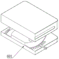
6. an angle adjusting mechanism; 601. rotating the connecting seat; 602. turning a handle; 603. scale marking; 604. a level gauge.
Detailed Description
The preferred embodiments of the present invention will be described in conjunction with the accompanying drawings, and it will be understood that they are presented herein only to illustrate and explain the present invention, and not to limit the present invention.
Example (b): as shown in fig. 1-8, the utility model provides a technical solution, a multi-angle photogrammetric survey device with light filling function, comprising a measuring bottom plate 1, wherein the top end of the measuring bottom plate 1 is rotatably connected with a measuring mounting plate 2, and the top end of the measuring mounting plate 2 is fixedly provided with a photogrammetric survey camera body 3;
the bottom center of the measuring bottom plate 1 is symmetrically connected with an adjusting support mechanism 4, and the adjusting support mechanism 4 comprises a fixed seat 401, a rotating support rod 402, a telescopic support rod 403, a fixed moving groove 404, a dismounting base 405, a taper pin 406, a fixed screw 407, a converging groove 408, a fixed soft plug 409 and a support spring 410;
the bottom center of the measuring bottom plate 1 is symmetrically connected with a fixed seat 401, the bottom of the fixed seat 401 is rotatably provided with a rotating support rod 402, the bottom of the rotating support rod 402 is embedded with a telescopic support rod 403, the outer side of the rotating support rod 402 is provided with a fixed moving groove 404, the bottom of the telescopic support rod 403 is engaged with a dismounting base 405, the bottom of the telescopic support rod 403 is provided with a taper foot 406 corresponding to the inner position of the dismounting base 405, the outer side of the telescopic support rod 403 is embedded with a fixed screw 407 corresponding to the fixed moving groove 404, the outer side of the telescopic support rod 403 is provided with a tightening groove 408 corresponding to the other end of the fixed screw 407, the other end of the fixed screw 407 is connected with a fixed soft plug 409 corresponding to the tightening groove 408, the top of the telescopic support rod 403 is connected with a support spring 410, the top of the support spring 410 is fixedly connected with the inner wall at the top end of, increasing the friction between the fixed cork 409 and the inner wall of the rotating support bar 402.
The top end of the photogrammetric camera body 3 is provided with an adjusting light supplement mechanism 5, and the adjusting light supplement mechanism 5 comprises a light supplement placing seat 501, a light supplement mounting seat 502, a fixing bolt 503, a light supplement lamp 504, a fixing groove 505, a light gathering cover 506, a light diffusing cover 507, a control switch 508, a transmission line 509 and a storage battery 510;
a light supplement placing seat 501 is installed at the top end of the photogrammetric camera body 3, a light supplement mounting seat 502 is installed at the top end of the light supplement placing seat 501, fixing bolts 503 are embedded and installed at four corners of the top end of the light supplement mounting seat 502, the light supplement mounting seat 502 and the light supplement placing seat 501 are fixedly installed through the fixing bolts 503, a light supplement lamp 504 is fixedly connected to the top end of the light supplement mounting seat 502, a fixing groove 505 is formed in one end of the light supplement lamp 504, a light gathering cover 506 is installed at one end of the light supplement lamp 504 through the fixing groove 505, a light scattering cover 507 is installed and connected at one end of the light gathering cover 506, a control switch 508 is connected to the position, corresponding to the light supplement placing seat 501, of the top end of the photogrammetric camera body 3, a transmission line 509 is connected to the other end of the light;
the input end of the control switch 508 is electrically connected with the output end of the storage battery 510, the output end of the control switch 508 is electrically connected with the input end of the light supplement lamp 504, the bottom end of the transmission line 509 is connected with the storage battery 510, and the light-gathering cover 506 is slidably connected with the fixing groove 505, so that the light-gathering cover 506 and the fixing groove 505 can be conveniently detached and installed.
An angle adjusting mechanism 6 is connected between the measuring bottom plate 1 and the measuring mounting plate 2, and the angle adjusting mechanism 6 comprises a rotating connecting seat 601, a rotating handle 602, a scale mark 603 and a level meter 604;
it is connected with and rotates even seat 601 to measure to rotate between bottom plate 1 and the measurement mounting panel 2, it is the unsmooth embedding type of upper and lower cylinder to rotate even seat 601, the outside symmetric connection who rotates even seat 601 has a commentaries on classics 602, the corresponding rotation of top of measuring bottom plate 1 links seat 601 outside position department and has evenly seted up scale mark 603, the spirit level 604 is installed in the one end embedding of measuring mounting panel 2, the quantity of scale mark 603 is 72, the angle between two adjacent scale marks 603 is 5 degrees, be convenient for carry out the accurate demonstration to the commentaries on classics 602 pivoted angle.
The utility model discloses a theory of operation and use flow: when the multi-angle photogrammetric survey device with the light supplementing function is used, the fixed screw 407 can be rotated and is connected with the telescopic supporting rod 403 through the meshing of the fixed screw 407, when the fixed screw 407 rotates, the fixed screw 407 and the fixed soft plug 409 are driven to move, the extension of the supporting spring 410 can drive the telescopic supporting rod 403 to move along the rotating supporting rod 402, thereby adjusting the position and distance between the telescopic support bar 403 and the rotary support bar 402, and after adjusting the position and distance between the telescopic support bar 403 and the rotary support bar 402, the fixed screw 407 is rotated to drive the fixed soft plug 409 at one end of the fixed screw 407 to move, the telescopic support bar 403 and the rotary support bar 402 can be fixed, and when the ground is uneven and difficult to place, the disassembling base 405 is taken down from the bottom end of the telescopic supporting rod 403, and the telescopic supporting rod 403 is stably supported through the taper foot 406;
when the photogrammetric camera body 3 is used for photogrammetric measurement, the control switch 508 can be pressed, so that the light filling lamp 504 is connected with the power supply of the storage battery 510, a user can select the light-gathering cover 506 or the light-diffusing cover 507 to be installed at one end of the light filling lamp 504 through the fixing groove 505 according to needs, the light filling effect of the light filling lamp 504 can be adjusted, and when the photogrammetric measurement camera body is not used, the light filling lamp 504 and the light filling installation seat 502 can be detached from the light filling placing seat 501 through the fixing bolt 503, so that light filling can be conveniently carried out during photogrammetric measurement;
rotate 602 through promoting, can drive and rotate even seat 601 and rotate even measurement mounting panel 2 on 601 top and rotate, can carry out the sign to the angle of 602 pivoted through scale mark 603 to when can carrying out multi-angle measurement, carry out accurate demonstration to the angle of rotation, combine to measure the spirit level 604 of mounting panel 2 one end embedding installation, can measure the horizontality of measuring mounting panel 2 and measuring mounting panel 2 top photogrammetry camera body 3.
Finally, it should be noted that: although the present invention has been described in detail with reference to the foregoing embodiments, it will be apparent to those skilled in the art that modifications may be made to the embodiments described in the foregoing embodiments, or equivalents may be substituted for elements thereof. Any modification, equivalent replacement, or improvement made within the spirit and principle of the present invention should be included in the protection scope of the present invention.
Claims (6)
1. A multi-angle photogrammetric device with a light supplementing function comprises a measuring bottom plate (1), wherein the top end of the measuring bottom plate (1) is rotatably connected with a measuring mounting plate (2), and a photogrammetric camera body (3) is fixedly mounted at the top end of the measuring mounting plate (2); the method is characterized in that:
the bottom center of the measuring bottom plate (1) is symmetrically connected with an adjusting and supporting mechanism (4), and the adjusting and supporting mechanism (4) comprises a fixed seat (401), a rotating supporting rod (402), a telescopic supporting rod (403), a fixed moving groove (404), a disassembling base (405), a taper pin (406), a fixed screw rod (407), a bundling groove (408), a fixed soft plug (409) and a supporting spring (410);
the bottom center of the measuring bottom plate (1) is symmetrically connected with a fixed seat (401), the bottom of the fixed seat (401) is rotatably provided with a rotating support rod (402), the bottom of the rotating support rod (402) is embedded with a telescopic support rod (403), the outer side of the rotating support rod (402) is provided with a fixed moving groove (404), the bottom of the telescopic support rod (403) is meshed with a dismounting base (405), the bottom of the telescopic support rod (403) is provided with a cone foot (406) corresponding to the inner position of the dismounting base (405), the outer side of the telescopic support rod (403) is provided with a fixed screw (407) corresponding to the fixed moving groove (404), the outer side of the telescopic support rod (403) is provided with a beam collecting groove (408) corresponding to the other end of the fixed screw (407), the other end of the fixed screw (407) is connected with a fixed soft plug (409) corresponding to the beam collecting groove (408, the top end of the telescopic supporting rod (403) is connected with a supporting spring (410).
2. The multi-angle photogrammetric device with light filling function of claim 1, characterized in that the top end of the supporting spring (410) is fixedly connected with the inner wall of the top end of the rotating supporting rod (402), and the inner wall of the rotating supporting rod (402) is uniformly provided with transverse anti-skidding threads corresponding to the position of the fixed soft plug (409).
3. The multi-angle photogrammetric device with the light supplementing function according to claim 1, characterized in that an adjusting light supplementing mechanism (5) is installed at the top end of the photogrammetric camera body (3), and the adjusting light supplementing mechanism (5) comprises a light supplementing placing seat (501), a light supplementing installing seat (502), a fixing bolt (503), a light supplementing lamp (504), a fixing groove (505), a light gathering cover (506), a light diffusing cover (507), a control switch (508), a transmission line (509) and a storage battery (510);
a light supplement placing seat (501) is installed at the top end of the photogrammetric camera body (3), a light supplement installing seat (502) is installed at the top end of the light supplement placing seat (501), fixing bolts (503) are embedded and installed at four corners of the top end of the light supplement installing seat (502), the light supplement installing seat (502) and the light supplement placing seat (501) are fixedly installed through the fixing bolts (503), a light supplement lamp (504) is fixedly connected to the top end of the light supplement installing seat (502), a fixing groove (505) is formed in one end of the light supplement lamp (504), a condensing hood (506) is installed at one end of the light supplement lamp (504) through the fixing groove (505), a light diffusing hood (507) is installed and connected to one end of the condensing hood (506), and a control switch (508) is connected to one side of the light supplement placing seat (501) corresponding to the top end of the photogrammetric camera body (3), the other end of the light supplement lamp (504) is connected with a transmission line (509), and a storage battery (510) is arranged at one end of the photogrammetric camera body (3) corresponding to the transmission line (509);
the input end of the control switch (508) is electrically connected with the output end of the storage battery (510), and the output end of the control switch (508) is electrically connected with the input end of the light supplement lamp (504).
4. The multi-angle photogrammetric apparatus with light supplement function as claimed in claim 3, wherein the bottom end of the transmission line (509) is connected with a storage battery (510), and the light-gathering cover (506) is slidably connected with the fixing groove (505).
5. The multi-angle photogrammetric device with light supplement function of claim 1, characterized in that an angle adjusting mechanism (6) is connected between the measuring bottom plate (1) and the measuring mounting plate (2), and the angle adjusting mechanism (6) comprises a rotary connecting seat (601), a rotating handle (602), a scale mark (603) and a level gauge (604);
it is connected with even seat (601) of rotation to measure between bottom plate (1) and the measurement mounting panel (2), the outside symmetric connection who rotates even seat (601) has a commentaries on classics (602), the top of measuring bottom plate (1) corresponds rotates even scale mark (603) of having seted up of seat (601) outside position department, spirit level (604) are installed in the one end embedding of measuring mounting panel (2).
6. The multi-angle photogrammetric apparatus with light filling function as claimed in claim 5, characterized in that the number of the scales (603) is 72, and the angle between two adjacent scales (603) is 5 degrees.
Priority Applications (1)
| Application Number | Priority Date | Filing Date | Title |
|---|---|---|---|
| CN201922093028.5U CN210833533U (en) | 2019-11-28 | 2019-11-28 | Multi-angle photogrammetric survey device with light filling function |
Applications Claiming Priority (1)
| Application Number | Priority Date | Filing Date | Title |
|---|---|---|---|
| CN201922093028.5U CN210833533U (en) | 2019-11-28 | 2019-11-28 | Multi-angle photogrammetric survey device with light filling function |
Publications (1)
| Publication Number | Publication Date |
|---|---|
| CN210833533U true CN210833533U (en) | 2020-06-23 |
Family
ID=71262501
Family Applications (1)
| Application Number | Title | Priority Date | Filing Date |
|---|---|---|---|
| CN201922093028.5U Active CN210833533U (en) | 2019-11-28 | 2019-11-28 | Multi-angle photogrammetric survey device with light filling function |
Country Status (1)
| Country | Link |
|---|---|
| CN (1) | CN210833533U (en) |
Cited By (2)
| Publication number | Priority date | Publication date | Assignee | Title |
|---|---|---|---|---|
| CN113280793A (en) * | 2021-05-27 | 2021-08-20 | 甘肃建筑职业技术学院 | Device is revised fast based on oblique photogrammetry |
| CN113607138A (en) * | 2021-10-09 | 2021-11-05 | 南通协同软件科技有限公司 | Multi-lens oblique photogrammetry camera based on remote software support |
-
2019
- 2019-11-28 CN CN201922093028.5U patent/CN210833533U/en active Active
Cited By (4)
| Publication number | Priority date | Publication date | Assignee | Title |
|---|---|---|---|---|
| CN113280793A (en) * | 2021-05-27 | 2021-08-20 | 甘肃建筑职业技术学院 | Device is revised fast based on oblique photogrammetry |
| CN113280793B (en) * | 2021-05-27 | 2022-11-01 | 甘肃建筑职业技术学院 | Device is revised fast based on oblique photogrammetry |
| CN113607138A (en) * | 2021-10-09 | 2021-11-05 | 南通协同软件科技有限公司 | Multi-lens oblique photogrammetry camera based on remote software support |
| CN113607138B (en) * | 2021-10-09 | 2021-12-24 | 南通协同软件科技有限公司 | Multi-lens oblique photogrammetry camera based on remote software support |
Similar Documents
| Publication | Publication Date | Title |
|---|---|---|
| CN105136111B (en) | A kind of construction level error and vertical survey instrument | |
| CN205981214U (en) | Novel overcasting staff | |
| CN210833533U (en) | Multi-angle photogrammetric survey device with light filling function | |
| CN209166412U (en) | A kind of inclination of transmission line tower measuring instrument | |
| CN116448065B (en) | Ground slope metering survey device for territorial space planning | |
| CN210862684U (en) | Construction site surveying and mapping device for engineering cost | |
| CN212080711U (en) | Measuring device for farmland measurement planning | |
| CN211667434U (en) | Surveying instrument with GPS function | |
| CN111982080A (en) | Terrain measuring device for territory space planning | |
| CN207585585U (en) | The cross reflective magnetic retaining device of laser range finder | |
| CN206891427U (en) | Road and bridge construction measurement apparatus | |
| CN202791187U (en) | Cartridge clip type measuring tripod | |
| CN214037663U (en) | On-spot mapping device of building engineering cost | |
| CN202994151U (en) | Multi-functional universal slope meter | |
| CN204718561U (en) | Portable electric pole gradient measurement instrument | |
| CN207487821U (en) | A kind of distribution photometer c- γ test fixtures | |
| CN104949752B (en) | Light illumination auxiliary test unit | |
| CN203480733U (en) | Horizontal modulus measurement demonstration instrument | |
| CN210689657U (en) | Sighting rod strutting arrangement is used in survey and drawing | |
| CN106352859B (en) | A kind of target plate component, Laser Line Marker component and its working method | |
| CN219244490U (en) | Counting device for land measurement | |
| CN215929096U (en) | Wisdom noise detection device for building site convenient to installation | |
| CN109489645A (en) | A kind of engineering mapping total station | |
| CN207600600U (en) | A kind of horizontal distribution photometer fixture | |
| CN214947639U (en) | A measuring equipment auxiliary fixture for highway surveys |
Legal Events
| Date | Code | Title | Description |
|---|---|---|---|
| GR01 | Patent grant | ||
| GR01 | Patent grant |