CN210823199U - Automatic labeling machine - Google Patents
Automatic labeling machine Download PDFInfo
- Publication number
- CN210823199U CN210823199U CN201921540340.8U CN201921540340U CN210823199U CN 210823199 U CN210823199 U CN 210823199U CN 201921540340 U CN201921540340 U CN 201921540340U CN 210823199 U CN210823199 U CN 210823199U
- Authority
- CN
- China
- Prior art keywords
- moving
- plate
- driving unit
- automatic labeling
- label
- Prior art date
- Legal status (The legal status is an assumption and is not a legal conclusion. Google has not performed a legal analysis and makes no representation as to the accuracy of the status listed.)
- Active
Links
Images
Abstract
The utility model discloses an automatic labeling machine, which comprises a machine table, and a label device, a sucker device and a moving device which are arranged on the machine table; the label device is arranged on a supporting plate, the supporting plate is connected with a transverse moving mechanism, and the transverse moving mechanism comprises a moving unit and a first driving unit; the sucking disc device comprises a sucking plate and a second driving unit; the moving device comprises a moving plate, a third driving unit and an adjustable jig, wherein the third driving unit drives the moving plate to reciprocate on a station, the jig is arranged on the moving plate, the jig comprises a base plate and a plurality of stop blocks which are movably arranged on the base plate, and the stop blocks jointly surround to form a placing space for placing a workpiece; borrow this, it has realized automatic printing label, and structural design is reasonable, and overall arrangement is ingenious to and, applicable in the work piece of equidimension specification not, improved adaptability greatly, be favorable to improving market competition.
Description
Technical Field
The utility model belongs to the technical field of the labeller and specifically relates to indicate an automatic labeling machine.
Background
In order to facilitate people to identify goods, the goods are generally labeled on the outer surface of the goods, a manual mode is generally adopted for labeling in the traditional technology, the working efficiency is low in such a mode, workers are easy to fatigue, and the production cost is high.
Therefore, a new technology needs to be developed to solve the above problems.
SUMMERY OF THE UTILITY MODEL
In view of this, the utility model discloses to the disappearance that prior art exists, its main objective provides an automatic labeling machine, and it has realized automatic printing label, and structural design is reasonable, and overall arrangement is ingenious to and, applicable work piece in not equidimension specification, improved adaptability greatly, be favorable to improving market competition.
In order to achieve the above purpose, the utility model adopts the following technical scheme:
an automatic labeling machine comprises a machine table, a label device, a sucker device and a moving device, wherein the label device, the sucker device and the moving device are arranged on the machine table; the machine table is provided with a station, and the label device, the sucker device and the moving device are arranged around the station;
the label device is arranged on a supporting plate, the supporting plate is connected with a transverse moving mechanism, the transverse moving mechanism is arranged on a machine table through a vertical frame, the transverse moving mechanism comprises a moving unit and a first driving unit for driving the moving unit, and the supporting plate is connected to the moving unit;
the sucking disc device is positioned on one side of the label device and comprises a sucking plate and a second driving unit, and the second driving unit drives the sucking plate to reciprocate up and down above the station;
the moving device comprises a moving plate, a third driving unit and an adjustable jig, wherein the third driving unit drives the moving plate to reciprocate on a station, the jig is installed on the moving plate, the jig comprises a base plate and a stop block arranged on the base plate in a movable mode, the stop block is provided with a plurality of stop blocks, and the stop blocks jointly enclose a placement space for placing a workpiece.
As a preferred scheme, the moving unit includes a first slide rail and a first slide block, the first slide block is adapted to the first slide rail, the first slide rail is disposed on the stand, the first slide block is connected to the first driving unit through a connecting block, and the supporting plate is connected to the first slide block.
As a preferred scheme, the sucker device further comprises a linkage rod, and two ends of the linkage rod are respectively connected to the second driving unit and the suction plate.
As a preferred scheme, the suction cup device further comprises a base, a sliding seat and a guide post, wherein the sliding seat and the guide post are arranged on the base, the base is connected to the supporting plate, the guide post penetrates through the sliding seat and is connected to the suction plate, and the second driving unit is installed on the sliding seat.
As a preferred scheme, the moving device further includes a second slide rail and a second slide block, the second slide rail is disposed on the machine platform, the second slide block is adapted to the second slide rail, the second slide block is connected to the third driving unit, and the moving plate is connected above the second slide block.
As a preferred scheme, a plurality of moving grooves are arranged on the base plate, the moving grooves are arranged at intervals, and a plurality of stop blocks are movably matched in the corresponding moving grooves.
As an optimal scheme, the automatic labeling machine further comprises a control platform, the control platform is arranged on the machine table and provided with a control device, and the label device, the sucker device and the moving device are electrically connected to the control device.
As a preferred scheme, the alarm is further arranged and arranged on the stand.
Compared with the prior art, the utility model have obvious advantage and beneficial effect, particularly, can know by above-mentioned technical scheme, it is mainly through label device, the sucking disc device, mobile device's combination sets up, and set up label device on lateral shifting mechanism, make it realize automatic printing label, and structural design is reasonable, overall arrangement is ingenious, and, set up the movable dog on the tool, make the adjustable size in place space on the tool, so, applicable in the work piece of equidimension specification not, the adaptability has been improved greatly, be favorable to improving market competition.
To more clearly illustrate the structural features and technical means of the present invention and the specific objects and functions achieved thereby, the present invention will be described in further detail with reference to the accompanying drawings and specific embodiments.
Drawings
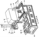
FIG. 1 is a perspective view of the overall structure of the embodiment of the present invention;
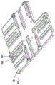
fig. 2 is a schematic structural diagram of a jig according to an embodiment of the present invention.
The attached drawings indicate the following:
10. machine table 20 and labeling device
30. Suction cup device 31, suction plate
32. Second driving unit 33 and linkage rod
34. Base 35, slide
36. Guide post 40 and moving device
41. Moving plate 42 and jig
421. Base plate 422 and stop block
423. Moving groove 43 and second slide rail
44. Second slide block
50. Support plate 60 and lateral movement mechanism
61. First slide rail 62, first slider
70. Stand 101 and control platform
102. An alarm.
Detailed Description
Fig. 1 to fig. 2 show a specific structure of an embodiment of the present invention.
First, it should be noted that in the following description, some terms such as "upper", "lower", etc. indicate orientations or positional relationships based on the orientations or positional relationships shown in the drawings, which are only for convenience of describing technical solutions of the present invention and simplifying the description, but do not indicate or imply that the referred devices or elements must have a specific orientation or be constructed and operated in a specific orientation, and thus, should not be construed as limiting the present invention.
The automatic labeling machine comprises a machine table 10, a label device 20 arranged on the machine table 10, a suction cup device 30 used for adsorbing labels, and a moving device 40 used for conveying a jig 42; a station is arranged on the machine table 10, and the label device 20, the suction cup device 30 and the moving device 40 are arranged around the station;
the label device 20 is mounted on a supporting plate 50, the supporting plate 50 is connected with a transverse moving mechanism 60, the transverse moving mechanism 60 is mounted on the machine station 10 through a vertical frame 70, the transverse moving mechanism 60 comprises a moving unit and a first driving unit for driving the moving unit, and the supporting plate 50 is connected to the moving unit; in the present embodiment, the label device 20 is a printer for printing labels; the suction cup device 30 is located at one side of the label device 20, the suction cup device 30 comprises a suction plate 31 and a second driving unit 32, and the second driving unit 32 drives the suction plate 31 to reciprocate up and down above the station;
the moving device 40 includes a moving plate 41, a third driving unit and an adjustable fixture 42, the third driving unit drives the moving plate 41 to reciprocate on the station, the fixture 42 is installed on the moving plate 41, the fixture 42 includes a base plate 421 and a plurality of blocks 422 movably disposed on the base plate 421, the blocks 422 have a plurality of blocks 422, and the blocks 422 together form a placing space for placing the workpiece. Borrow this, through the combination setting of label device 20, sucking disc device 30, mobile device 40 to set up label device 20 on lateral shifting mechanism 60, make it realize automatic label of printing, and structural design is reasonable, overall arrangement is ingenious, and, set up movable dog 422 on tool 42, make the adjustable size in place space on tool 42, so, applicable in the work piece of not equidimension specification, the adaptability has been improved greatly, be favorable to improving market competition.
Specifically, the moving unit includes a first slide rail 61 and a first slide block 62, the first slide block 62 is adapted to the first slide rail 61, the first slide rail 61 is disposed on the stand 70, the first slide block 62 is connected to the first driving unit through a connecting block, and the supporting plate 50 is connected to the first slide block 62. Therefore, the moving structure of the label device 20 can be simplified through the matching of the sliding rail and the sliding block, and the longer movement of the label device can be realized, so that the processing requirement can be better met.
The sucker device 30 further comprises a linkage rod 33, and two ends of the linkage rod 33 are respectively connected to the second driving unit 32 and the suction plate 31; the suction cup device 30 further includes a base 34, a sliding seat 35 disposed on the base 34, and a guide post 36, wherein the base 34 is connected to the supporting plate 50, the guide post 36 passes through the sliding seat 35 and is connected to the suction plate 31, and the second driving unit 32 is mounted on the sliding seat 35.
The moving device 40 further includes a second slide rail 43 and a second slider 44, the second slide rail 43 is disposed on the machine table 10, the second slider 44 is adapted to the second slide rail 43, the second slider 44 is connected to the third driving unit, and the moving plate 41 is connected above the second slider 44.
The base plate 421 is provided with a plurality of moving grooves 423, the moving grooves 423 are arranged at intervals, and the stoppers 422 are movably fitted in the corresponding moving grooves 423. In this embodiment, preferably, the substrate 421 has a rectangular structure, and the plurality of moving grooves 423 are respectively defined as a first side moving groove, a second side moving groove, a third side moving groove, and a fourth side moving groove, and the first side moving groove, the second side moving groove, the third side moving groove, and the fourth side moving groove respectively extend from the inside of the rectangle toward four sides; in addition, a notch is formed at one corner of the substrate 421 with the rectangular structure, so that the overall weight of the substrate 421 is reduced, and manufacturing materials are saved. Thus, the movable groove 423 is disposed at different positions of the substrate 421, so that the stoppers 422 are disposed at different positions of the substrate 421, so that the stoppers 422 block different portions of the workpiece, thereby improving positioning stability.
In addition, in this embodiment, the machine table 10 is further provided with a control platform 101, the control platform 101 is provided with a control device, and the label device 20, the suction cup device 30, and the moving device 40 are all electrically connected to the control device.
In addition, in this embodiment, the machine 10 is further provided with an alarm 102, the alarm 102 is arranged on the stand 70, and the alarm 102 is electrically connected to the control device; therefore, the alarm 102 can monitor the operation safety of the machine 10 in real time and discover abnormal conditions in time.
To sum up, the utility model discloses a design focus lies in, and it mainly is through the combination setting of label device, sucking disc device, mobile device to set up label device on lateral shifting mechanism, make it realize automatic printing label, and structural design is reasonable, and overall arrangement is ingenious, and set up the movable dog on the tool, make the adjustable size in space of putting on the tool, so, applicable work piece in not equidimension specification has improved the adaptability greatly, is favorable to improving market competition.
The above description is only a preferred embodiment of the present invention, and is not intended to limit the technical scope of the present invention, so that any slight modifications, equivalent changes and modifications made by the technical spirit of the present invention to the above embodiments are all within the scope of the technical solution of the present invention.
Claims (8)
1. An automatic labeling machine which characterized in that: the label device is arranged on the machine table, the sucker device is used for adsorbing a label, and the moving device is used for conveying a jig; the machine table is provided with a station, and the label device, the sucker device and the moving device are arranged around the station;
the label device is arranged on a supporting plate, the supporting plate is connected with a transverse moving mechanism, the transverse moving mechanism is arranged on a machine table through a vertical frame, the transverse moving mechanism comprises a moving unit and a first driving unit for driving the moving unit, and the supporting plate is connected to the moving unit;
the sucking disc device is positioned on one side of the label device and comprises a sucking plate and a second driving unit, and the second driving unit drives the sucking plate to reciprocate up and down above the station;
the moving device comprises a moving plate, a third driving unit and an adjustable jig, wherein the third driving unit drives the moving plate to reciprocate on a station, the jig is installed on the moving plate, the jig comprises a base plate and a stop block arranged on the base plate in a movable mode, the stop block is provided with a plurality of stop blocks, and the stop blocks jointly enclose a placement space for placing a workpiece.
2. The automatic labeling machine according to claim 1, characterized in that: the moving unit comprises a first sliding rail and a first sliding block, the first sliding block is matched with the first sliding rail, the first sliding rail is arranged on the vertical frame, the first sliding block is connected to the first driving unit through a connecting block, and the supporting plate is connected to the first sliding block.
3. The automatic labeling machine according to claim 1, characterized in that: the sucker device further comprises a linkage rod, and two ends of the linkage rod are respectively connected to the second driving unit and the suction plate.
4. The automatic labeling machine according to claim 3, characterized in that: the sucking disc device further comprises a base, a sliding seat and a guide post, wherein the sliding seat and the guide post are arranged on the base, the base is connected to the supporting plate, the guide post penetrates through the sliding seat and is connected to the sucking plate, and the second driving unit is installed on the sliding seat.
5. The automatic labeling machine according to claim 1, characterized in that: the moving device further comprises a second sliding rail and a second sliding block, the second sliding rail is arranged on the machine table, the second sliding block is adaptive to the second sliding rail, the second sliding block is connected to the third driving unit, and the moving plate is connected to the upper portion of the second sliding block.
6. The automatic labeling machine according to claim 1, characterized in that: the base plate is provided with a plurality of moving grooves which are arranged at intervals, and a plurality of stop blocks are movably matched in the corresponding moving grooves.
7. The automatic labeling machine according to claim 1, characterized in that: still including control platform, control platform sets up on the board, control platform is provided with controlling means, the equal electric connection of label device, sucking disc device, mobile device is in controlling means.
8. The automatic labeling machine according to claim 1, characterized in that: still be provided with the alarm, the alarm sets up on the grudging post.
Priority Applications (1)
| Application Number | Priority Date | Filing Date | Title |
|---|---|---|---|
| CN201921540340.8U CN210823199U (en) | 2019-09-17 | 2019-09-17 | Automatic labeling machine |
Applications Claiming Priority (1)
| Application Number | Priority Date | Filing Date | Title |
|---|---|---|---|
| CN201921540340.8U CN210823199U (en) | 2019-09-17 | 2019-09-17 | Automatic labeling machine |
Publications (1)
| Publication Number | Publication Date |
|---|---|
| CN210823199U true CN210823199U (en) | 2020-06-23 |
Family
ID=71276841
Family Applications (1)
| Application Number | Title | Priority Date | Filing Date |
|---|---|---|---|
| CN201921540340.8U Active CN210823199U (en) | 2019-09-17 | 2019-09-17 | Automatic labeling machine |
Country Status (1)
| Country | Link |
|---|---|
| CN (1) | CN210823199U (en) |
-
2019
- 2019-09-17 CN CN201921540340.8U patent/CN210823199U/en active Active
Similar Documents
| Publication | Publication Date | Title |
|---|---|---|
| CN110364349B (en) | Transformer iron core chip lamination mechanism, device and lamination machine | |
| CN213651724U (en) | Lifting trolley | |
| CN110902321A (en) | Drawer type tray feeding machine | |
| CN114406649A (en) | Scissor assembly mechanism for keyboard keys | |
| CN210823199U (en) | Automatic labeling machine | |
| CN108032117B (en) | Battery tray cutting jig | |
| CN216681043U (en) | Scissor assembly mechanism for keyboard keys | |
| CN214383128U (en) | Adjustable support that punching press end effector off-line was built | |
| CN214114068U (en) | Single-power dislocation cutting device | |
| CN212173917U (en) | Paper feeding device of gilding press | |
| CN212191979U (en) | Battery disassembling device | |
| CN210837682U (en) | Novel solid brilliant machine material receiving system | |
| CN215046660U (en) | Secondary positioning mechanism for turntable carrier | |
| CN220120904U (en) | Automatic inductance testing device | |
| CN220701635U (en) | Loading attachment convenient to automatic accurate subsides mark | |
| CN206475547U (en) | A kind of glass heating membrane mounting tool | |
| CN210788778U (en) | Punch forming mechanism of signal receiving connecting pin of special mining machinery | |
| CN220840602U (en) | Position leaning device mounted on mobile machine head and capable of pushing large and small plates | |
| CN216182927U (en) | Umbrella pearl rigging equipment | |
| CN220672636U (en) | Blade battery stacking machine | |
| CN212946364U (en) | Full-automatic kludge of intelligence stereo set equipment magnet | |
| CN117141818B (en) | Battery module reverse box-placing machine and use method thereof | |
| CN212502904U (en) | A equipment for pile up neatly of cotton flannel product | |
| CN218947018U (en) | Round bar material clamp | |
| CN212461650U (en) | Grabbing and conveying mechanism |
Legal Events
| Date | Code | Title | Description |
|---|---|---|---|
| GR01 | Patent grant | ||
| GR01 | Patent grant | ||
| TR01 | Transfer of patent right | ||
| TR01 | Transfer of patent right |
Effective date of registration: 20200922 Address after: 710000 unit 1707, building 1, Wanke hi tech living Plaza, No.56 Xifeng Road, Yanta District, Xi'an, Shaanxi Province Patentee after: Xi'an Boxin Chuangda Electronic Technology Co., Ltd Address before: 523000 No. 12, ancient Liao Road, Tangxia Town, Dongguan, Guangdong Patentee before: DONGGUAN GUOCI NEW MATERIAL TECHNOLOGY Co.,Ltd. |