CN210807156U - Adjustable new energy solar power generation device - Google Patents
Adjustable new energy solar power generation device Download PDFInfo
- Publication number
- CN210807156U CN210807156U CN201922336749.4U CN201922336749U CN210807156U CN 210807156 U CN210807156 U CN 210807156U CN 201922336749 U CN201922336749 U CN 201922336749U CN 210807156 U CN210807156 U CN 210807156U
- Authority
- CN
- China
- Prior art keywords
- photovoltaic module
- solar power
- energy solar
- cylinder
- assembly
- Prior art date
- Legal status (The legal status is an assumption and is not a legal conclusion. Google has not performed a legal analysis and makes no representation as to the accuracy of the status listed.)
- Active
Links
Images


Classifications
-
- Y—GENERAL TAGGING OF NEW TECHNOLOGICAL DEVELOPMENTS; GENERAL TAGGING OF CROSS-SECTIONAL TECHNOLOGIES SPANNING OVER SEVERAL SECTIONS OF THE IPC; TECHNICAL SUBJECTS COVERED BY FORMER USPC CROSS-REFERENCE ART COLLECTIONS [XRACs] AND DIGESTS
- Y02—TECHNOLOGIES OR APPLICATIONS FOR MITIGATION OR ADAPTATION AGAINST CLIMATE CHANGE
- Y02E—REDUCTION OF GREENHOUSE GAS [GHG] EMISSIONS, RELATED TO ENERGY GENERATION, TRANSMISSION OR DISTRIBUTION
- Y02E10/00—Energy generation through renewable energy sources
- Y02E10/40—Solar thermal energy, e.g. solar towers
- Y02E10/47—Mountings or tracking
-
- Y—GENERAL TAGGING OF NEW TECHNOLOGICAL DEVELOPMENTS; GENERAL TAGGING OF CROSS-SECTIONAL TECHNOLOGIES SPANNING OVER SEVERAL SECTIONS OF THE IPC; TECHNICAL SUBJECTS COVERED BY FORMER USPC CROSS-REFERENCE ART COLLECTIONS [XRACs] AND DIGESTS
- Y02—TECHNOLOGIES OR APPLICATIONS FOR MITIGATION OR ADAPTATION AGAINST CLIMATE CHANGE
- Y02E—REDUCTION OF GREENHOUSE GAS [GHG] EMISSIONS, RELATED TO ENERGY GENERATION, TRANSMISSION OR DISTRIBUTION
- Y02E10/00—Energy generation through renewable energy sources
- Y02E10/50—Photovoltaic [PV] energy
Landscapes
- Photovoltaic Devices (AREA)
Abstract
The utility model discloses an adjustable new energy solar power generation device, including photovoltaic module, rotating assembly and installation adjustment mechanism, can supply the rotating assembly that photovoltaic module lower extreme was placed passes through the fix with screw on the installation face, installation adjustment mechanism is located photovoltaic module upper end bottom, and it includes adjusting assembly, cylinder and places the board, the support passes through the fix with screw under the photovoltaic module upper end, the cylinder is fixed on the support upper surface, place the board detachable and install at the photovoltaic module top, and the lower fixed surface has the slide, the slide lower surface is provided with the spout, adjusting assembly one end is installed on the piston rod in the cylinder; the utility model discloses a be provided with installation adjustment mechanism, can realize firm to photovoltaic module's installation, the inclination of conveniently adjusting photovoltaic module 1 according to the condition again makes its better acceptance illumination, reduces the improper influence to new forms of energy solar energy power generation of inclination, and easy operation convenient to use.
Description
Technical Field
The utility model belongs to the technical field of new forms of energy solar energy power generation, concretely relates to new forms of energy solar power generation facility with adjustable is the photovoltaic board that new forms of energy solar energy power generation used with adjustable very much.
Background
The new energy is also called unconventional energy, refers to various energy forms other than traditional energy, and is generally renewable energy developed and utilized on the basis of new technology, such as solar energy, geothermal energy, wind energy, ocean energy, biomass energy, nuclear fusion energy and the like. Solar photovoltaic power generation refers to a power generation mode of directly converting light energy into electric energy without a thermal process. Photovoltaic panel assemblies are electrical power generating devices that produce direct current electricity when exposed to sunlight and are comprised of thin solid photovoltaic cells made almost entirely of semiconductor materials such as silicon.
When some existing photovoltaic panels for solar power generation are installed, the inclination angles of the existing photovoltaic panels are usually fixed or inconvenient to adjust, so that when the existing photovoltaic panels need to be adjusted so as to be better illuminated, the problem is troublesome, and therefore a new adjustable solar power generation device is provided.
SUMMERY OF THE UTILITY MODEL
An object of the utility model is to provide a new energy solar power system with adjustable to when solving some photovoltaic boards that are used for solar power system that propose among the above-mentioned background art and installing, its inclination all is fixed or inconvenient regulation usually, consequently adjusts so that its better when accepting the illumination during operation, comparatively trouble problem to the photovoltaic board as needs.
In order to achieve the above object, the utility model provides a following technical scheme: the utility model provides a new energy solar power system with adjustable, includes photovoltaic module, runner assembly and installation adjustment mechanism, can supply the runner assembly that the photovoltaic module lower extreme was placed passes through the fix with screw on the installation face, installation adjustment mechanism is located photovoltaic module upper end bottom, and it includes adjusting part, cylinder and places the board, the support passes through fix with screw under the photovoltaic module upper end, the cylinder is fixed at the support upper surface, it installs at the photovoltaic module top to place the board detachable, and lower fixed surface has the slide, the slide lower surface is provided with the spout, adjusting part one end is installed on the piston rod in the cylinder, and the other end can stretch into in the spout.
Preferably, the main section of the placing plate is L-shaped, fastening screws are arranged on two sides of the placing plate, one ends of the fastening screws are exposed outside, hand wheels are fixed on the end portions of the fastening screws, threads on the other ends of the fastening screws penetrate through the placing plate in a screwing mode, and the end portions of the fastening screws are in contact with the side face of the photovoltaic module.
Preferably, the adjusting part comprises a rotating ball, a telescopic rod and a connecting rod, the lower end of the connecting rod is mounted on a piston rod in the cylinder through a rotating shaft, the upper end of the connecting rod is connected with a rotating shaft at one end of the telescopic rod, the telescopic rod is extensible or shortened in length, the other end of the telescopic rod extends into the rotating ball, and the rotating ball is located in the sliding groove.
Preferably, the rotating ball is connected with the end bearing of the telescopic rod, the rotating ball can rotate, and the rotating ball can slide in the sliding groove.
Preferably, the rotating assembly supported by the photovoltaic assembly comprises supporting vertical plates, fixing shafts and mounting plates, the supporting vertical plates are vertically fixed on the mounting surface through screws, the two fixing shafts are relatively fixed on opposite surfaces of the supporting vertical plates, the mounting plates are horizontally arranged between the two supporting vertical plates, and clamping grooves are formed in positions, corresponding to the fixing shafts, of two sides of the mounting plates.
Preferably, the fixed shaft extends into the clamping groove, a rectangular groove for placing the photovoltaic assembly is formed in the surface of the mounting plate, and the mounting plate can rotate around the fixed shaft.
Compared with the prior art, the beneficial effects of the utility model are that:
(1) the utility model discloses a be provided with installation adjustment mechanism, can realize firm to photovoltaic module's installation, the inclination of conveniently adjusting photovoltaic module 1 according to the condition again makes its better acceptance illumination, reduces the improper influence to new forms of energy solar energy power generation of inclination, and easy operation convenient to use.
(2) The utility model discloses a be provided with runner assembly, both can play the support installation effect to photovoltaic module, adjust not producing the influence again to photovoltaic module's rotation.
Drawings
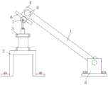
Fig. 1 is a schematic structural view of the present invention;
FIG. 2 is a schematic view of the local internal structure of the placement plate and the fastening screw according to the present invention;
FIG. 3 is a schematic view of the internal structure of the adjusting assembly of the present invention;
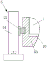
FIG. 4 is a schematic view of the right-view internal partial structure of the rotating assembly of the present invention;
in the figure: 1. a photovoltaic module; 2. a support; 3. a cylinder; 4. placing the plate; 5. a rotating assembly; 51. supporting a vertical plate; 52. a fixed shaft; 53. mounting a plate; 6. a slide plate; 7. an adjustment assembly; 71. rotating the ball; 72. a telescopic rod; 73. a connecting rod; 8. fastening a screw rod; 9. a chute; 10. a rectangular groove.
Detailed Description
The technical solutions in the embodiments of the present invention will be described clearly and completely with reference to the accompanying drawings in the embodiments of the present invention, and it is obvious that the described embodiments are only some embodiments of the present invention, not all embodiments. Based on the embodiments in the present invention, all other embodiments obtained by a person skilled in the art without creative work belong to the protection scope of the present invention.
Referring to fig. 1-4, the present invention provides a technical solution: an adjustable new energy solar power generation device comprises a photovoltaic module 1, a rotating module 5 and an installation adjusting mechanism, wherein the rotating module 5 which can be placed at the lower end of the photovoltaic module 1 is fixed on a mounting surface through screws, the installation adjusting mechanism is positioned at the bottom of the upper end of the photovoltaic module 1 and comprises an adjusting module 7, a cylinder 3 and a placing plate 4, a support 2 is fixed under the upper end of the photovoltaic module 1 through screws, the cylinder 3 is fixed on the upper surface of the support 2, the placing plate 4 is detachably arranged at the top of the photovoltaic module 1, a sliding plate 6 is fixed on the lower surface of the photovoltaic module 1, a sliding groove 9 is formed in the lower surface of the sliding plate 6, one end of the adjusting module 7 is arranged on a piston rod in the cylinder 3, the other end of the adjusting module can extend into the sliding groove 9, the main section of the placing plate 4 is L-shaped, fastening screw rods 8, the other end screw thread closes soon and passes and places board 4, and tip and the contact of photovoltaic module 1 side, through being provided with installation adjustment mechanism, can realize the installation to photovoltaic module 1 firm, conveniently adjust photovoltaic module 1's inclination as the condition again, make its better acceptance illumination, reduce the improper influence to new forms of energy solar energy power generation of inclination, and easy operation convenient to use.
In this embodiment, preferably, the adjusting assembly 7 includes a rotating ball 71, an expansion link 72 and a connecting rod 73, the lower end of the connecting rod 73 is mounted on a piston rod in the cylinder 3 through a rotating shaft, the upper end of the connecting rod is connected with a rotating shaft at one end of the expansion link 72, the expansion link 72 is extendable or retractable in length, the other end of the expansion link 72 extends into the rotating ball 71, the rotating ball 71 is located in the sliding slot 9, the rotating ball 71 is connected with an end bearing of the expansion link 72, and is connected through a plurality of rotating shafts, so that the rotating ball is rotated along with the movement of the photovoltaic assembly 1, and the rotating ball 71 does not affect the rotation, and the rotating ball 71 can slide in the sliding slot 9, and by providing the adjusting assembly 7, the rotating ball is changed along with the.
In this embodiment, preferably, the rotating assembly 5 supported by the photovoltaic assembly 1 includes a supporting vertical plate 51, a fixing shaft 52 and a mounting plate 53, the supporting vertical plate 51 is vertically fixed on the mounting surface through screws, the two fixing shafts 52 are relatively fixed on the opposite surfaces of the supporting vertical plate 51, the mounting plate 53 is horizontally located between the two supporting vertical plates 51, and the two sides of the mounting plate are provided with clamping grooves corresponding to the fixing shafts 52, the fixing shafts 52 extend into the clamping grooves, the surface of the mounting plate 53 is provided with a rectangular groove 10 for placing the photovoltaic assembly 1, the mounting plate 53 can rotate around the fixing shaft 52, through the rotating assembly 5, the supporting and mounting effects can be achieved on the photovoltaic assembly 1, and the rotation adjustment of the photovoltaic assembly 1 is not influenced.
The utility model discloses a theory of operation and use flow: when the utility model is used, the photovoltaic module 1 is firstly installed on the fixed installation adjusting mechanism and the rotating component 5, then the hand wheel is held to rotate the fastening screw 8, so that the relative movement is carried out until the photovoltaic module 1 is contacted with the side surface of the photovoltaic module 1, the photovoltaic module 1 can be fastened, after the photovoltaic module 1 is installed, if the inclination angle of the photovoltaic module 1 is not proper, the cylinder 3(SC) can be opened, the piston rod in the cylinder 3 moves upwards or downwards to drive the adjusting component 7 to move, the adjusting component 7 can drive the photovoltaic module 1 to move upwards or downwards, and meanwhile, the lower end of the photovoltaic module 1 can drive the mounting plate 53 to rotate around the fixed shaft 52; during again, the length of telescopic link 72 can extend or shorten, and whole can rotate along with photovoltaic module 1's removal, connecting rod 73 can rotate along with telescopic link 72's rotation simultaneously, ball 71 rotates and slides in spout 9 internal rotation, whole process neither influences the change of photovoltaic module 1 angle, and easy operation convenient to use, make things convenient for the work of photovoltaic module 1 of new forms of energy solar energy power generation usefulness through this kind of setting up, and conveniently adjust inclination as required, reduce the factor that influences new forms of energy solar energy power generation.
Although embodiments of the present invention have been shown and described, it will be appreciated by those skilled in the art that changes, modifications, substitutions and alterations can be made in these embodiments without departing from the principles and spirit of the invention, the scope of which is defined in the appended claims and their equivalents.
Claims (6)
1. The utility model provides a new energy solar power system with adjustable, includes photovoltaic module (1), runner assembly (5) and installation adjustment mechanism, its characterized in that: can supply rotating assembly (5) that photovoltaic module (1) lower extreme was placed passes through fix with screw on the installation face, installation adjustment mechanism is located photovoltaic module (1) upper end bottom, and it includes adjusting part (7), cylinder (3) and places board (4), cylinder (3) are fixed at support (2) upper surface, support (2) pass through fix with screw under photovoltaic module (1) upper end, place board (4) detachable the installing at photovoltaic module (1) top, and lower fixed surface has slide (6), slide (6) lower surface is provided with spout (9), adjusting part (7) one end is installed on the piston rod in cylinder (3), and the other end can stretch into in spout (9).
2. The new and adjustable energy solar power plant as claimed in claim 1, wherein: the cross section of the main view of the placing plate (4) is L-shaped, the two sides of the placing plate are provided with fastening screws (8), one ends of the fastening screws (8) are exposed to the outer side, the end parts of the fastening screws are fixed with hand wheels, the threads of the other ends of the fastening screws penetrate through the placing plate (4), and the end parts of the fastening screws are in contact with the side surface of the photovoltaic module (1).
3. The new and adjustable energy solar power plant as claimed in claim 1, wherein: adjusting part (7) include rotating ball (71), telescopic link (72) and connecting rod (73), connecting rod (73) lower extreme is installed on the piston rod in cylinder (3) through the pivot, and the upper end is connected with the one end pivot of telescopic link (72), telescopic link (72) length is extendible or shorten, in the rotating ball (71) was stretched into to telescopic link (72) other end, rotating ball (71) are arranged in spout (9).
4. The new and adjustable energy solar power plant as in claim 3, wherein: the rotating ball (71) is connected with the end bearing of the telescopic rod (72), the rotating ball (71) can rotate, and the rotating ball (71) can slide in the sliding groove (9).
5. The new and adjustable energy solar power plant as claimed in claim 1, wherein: the rotating assembly (5) for supporting the photovoltaic assembly (1) comprises supporting vertical plates (51), fixing shafts (52) and mounting plates (53), the supporting vertical plates (51) are vertically fixed on a mounting surface through screws, the two fixing shafts (52) are relatively fixed on opposite surfaces of the supporting vertical plates (51), the mounting plates (53) are horizontally located between the two supporting vertical plates (51), and clamping grooves are formed in positions, corresponding to the fixing shafts (52), of two sides of each mounting plate.
6. The new and adjustable energy solar power plant as claimed in claim 5, wherein: the fixing shaft (52) extends into the clamping groove, the surface of the mounting plate (53) is provided with a rectangular groove (10) for placing the photovoltaic assembly (1), and the mounting plate (53) can rotate around the fixing shaft (52).
Priority Applications (1)
| Application Number | Priority Date | Filing Date | Title |
|---|---|---|---|
| CN201922336749.4U CN210807156U (en) | 2019-12-24 | 2019-12-24 | Adjustable new energy solar power generation device |
Applications Claiming Priority (1)
| Application Number | Priority Date | Filing Date | Title |
|---|---|---|---|
| CN201922336749.4U CN210807156U (en) | 2019-12-24 | 2019-12-24 | Adjustable new energy solar power generation device |
Publications (1)
| Publication Number | Publication Date |
|---|---|
| CN210807156U true CN210807156U (en) | 2020-06-19 |
Family
ID=71228815
Family Applications (1)
| Application Number | Title | Priority Date | Filing Date |
|---|---|---|---|
| CN201922336749.4U Active CN210807156U (en) | 2019-12-24 | 2019-12-24 | Adjustable new energy solar power generation device |
Country Status (1)
| Country | Link |
|---|---|
| CN (1) | CN210807156U (en) |
Cited By (1)
| Publication number | Priority date | Publication date | Assignee | Title |
|---|---|---|---|---|
| CN114337494A (en) * | 2022-01-07 | 2022-04-12 | 徐州日托光伏科技有限公司 | Automatic angle-adjusting self-locking structure of photovoltaic bracket |
-
2019
- 2019-12-24 CN CN201922336749.4U patent/CN210807156U/en active Active
Cited By (1)
| Publication number | Priority date | Publication date | Assignee | Title |
|---|---|---|---|---|
| CN114337494A (en) * | 2022-01-07 | 2022-04-12 | 徐州日托光伏科技有限公司 | Automatic angle-adjusting self-locking structure of photovoltaic bracket |
Similar Documents
| Publication | Publication Date | Title |
|---|---|---|
| CN110855225A (en) | Adjustable new energy solar power generation device | |
| CN217282837U (en) | Adjustable installing support of photovoltaic board convenient to dismouting | |
| CN210807156U (en) | Adjustable new energy solar power generation device | |
| CN205901663U (en) | Solar photovoltaic power generation adjustable fixing support device | |
| CN207968404U (en) | Regulating mechanism applied to roof North and South direction solar-tracking system | |
| CN213027923U (en) | Photovoltaic power generation device of easy installation | |
| CN210041719U (en) | Photovoltaic power generation installing support | |
| CN217522765U (en) | High adaptability photovoltaic power generation station photovoltaic board support frame | |
| CN216959751U (en) | Photovoltaic support convenient to angle of adjustment | |
| CN107994853A (en) | A kind of rotatable solar power generation fixed frame | |
| CN217388617U (en) | Photovoltaic power generation assembly with function of adjusting illumination receiving area | |
| CN220210341U (en) | Photovoltaic panel installing support | |
| CN216356578U (en) | Solar panel convenient to adjust | |
| CN214014164U (en) | Connecting equipment for solar photovoltaic module | |
| CN220234616U (en) | Solar panel module capable of improving light receiving rate | |
| CN215498822U (en) | Adjusting mechanism of photovoltaic panel for solar power generation | |
| CN219980714U (en) | Photovoltaic roofing connection structure | |
| CN216721247U (en) | Photovoltaic board strutting arrangement who has regulation structure for photovoltaic power generation | |
| CN221227425U (en) | Photovoltaic panel fixing device for photovoltaic power generation | |
| CN221305804U (en) | Photovoltaic supporting mechanism | |
| CN217428051U (en) | Photovoltaic board installing support of angularly adjustable | |
| CN218734048U (en) | Photovoltaic support convenient to adjust | |
| CN215581007U (en) | Supporting component convenient to adjust for photovoltaic power generation | |
| CN220822982U (en) | Photovoltaic power generation device | |
| CN218850698U (en) | Photovoltaic power generation board installing support that can adjust to angle automatically |
Legal Events
| Date | Code | Title | Description |
|---|---|---|---|
| GR01 | Patent grant | ||
| GR01 | Patent grant |