CN210807030U - A fixture device for permanent-magnet machine assembly - Google Patents
A fixture device for permanent-magnet machine assembly Download PDFInfo
- Publication number
- CN210807030U CN210807030U CN201922265637.4U CN201922265637U CN210807030U CN 210807030 U CN210807030 U CN 210807030U CN 201922265637 U CN201922265637 U CN 201922265637U CN 210807030 U CN210807030 U CN 210807030U
- Authority
- CN
- China
- Prior art keywords
- groove
- moving
- rod
- permanent
- base
- Prior art date
- Legal status (The legal status is an assumption and is not a legal conclusion. Google has not performed a legal analysis and makes no representation as to the accuracy of the status listed.)
- Active
Links
Images


Landscapes
- Permanent Field Magnets Of Synchronous Machinery (AREA)
Abstract
The utility model belongs to permanent-magnet machine rigging equipment field, especially, a fixture device for permanent-magnet machine assembly, when installing to current permanent-magnet machine, mostly all be the manual work and assemble, because the magnetic field effect between rotor and the stator in the assembling process for the installation is inconvenient, and then influences the problem of the efficiency of assembly, now proposes following scheme, and it includes the base, the top fixed mounting of base has the backup pad that two symmetries set up, and the top fixed mounting of two backup pads has same roof, and the sliding tray has all been seted up with the bottom of roof at the top of base, and the sliding tray internal rotation is connected with two-way screw rod, and fixed mounting has the motor on one side inner wall of a sliding tray in two sliding trays, two-way screw rod fixed connection in the output shaft of motor and two-way screw rod. The utility model discloses simple structure, convenient to use can make the quick assembly that assembles of permanent-magnet machine, makes things convenient for people to use.
Description
Technical Field
The utility model relates to a permanent-magnet machine rigging equipment technical field especially relates to an anchor clamps device for permanent-magnet machine assembly.
Background
The permanent magnet motor is a permanent magnet excitation motor, and in the assembly process of a motor assembly, because a rotor has a strong magnetic field, a motor shell is heavy, if a special assembly tool is not available, the rotor and a stator are difficult to assemble together, the disassembly is also the same, and the friction between the rotor and the stator can damage a magnetic steel sheet and a winding.
When an existing permanent magnet motor is installed, mostly manual assembly is carried out, and in the assembling process, due to the magnetic field effect between a rotor and a stator, installation is inconvenient, the assembling efficiency is further influenced, and therefore a fixture device for assembling the permanent magnet motor is provided.
SUMMERY OF THE UTILITY MODEL
The utility model aims at solving current permanent-magnet machine and when installing, mostly all be the manual work and assemble, because the magnetic field effect between rotor and the stator in assembling process for the installation is inconvenient, and then influences the shortcoming of the efficiency of assembly, and the fixture device who is used for permanent-magnet machine assembly that proposes.
In order to achieve the above purpose, the utility model adopts the following technical scheme:
a clamp device for assembling a permanent magnet motor comprises a base, wherein two symmetrically arranged support plates are fixedly arranged at the top of the base, the top of each support plate is fixedly provided with a same top plate, sliding grooves are respectively formed in the top of the base and the bottom of the top plate, a bidirectional screw rod is rotationally connected in each sliding groove, a motor is fixedly arranged on the inner wall of one side of one sliding groove in each sliding groove, the output shaft of each motor is fixedly connected with one bidirectional screw rod in each bidirectional screw rod and is in transmission connection with the two bidirectional screw rods, two symmetrically arranged movable plates are sleeved on the two bidirectional screw rods in a threaded manner, moving grooves are respectively formed in the sides, close to each other, of the two movable plates, a rotating rod is rotationally connected to the inner wall of each moving groove, two symmetrically arranged moving blocks are slidably connected to the rotating rod, an arc-shaped clamping plate is fixedly, and a moving rod is fixedly arranged on a piston of the cylinder and is in sliding connection with the two rotating rods.
Preferably, the outer sides of the two bidirectional screws are fixedly sleeved with belt pulleys, the two belt pulleys are in transmission connection with a same belt, and the rotating bidirectional screws can drive the rotation of the other bidirectional screw through the transmission connection of the belt pulleys and the belt.
Preferably, two threaded grooves which are symmetrically arranged are formed in the outer side of the rotating rod, a positioning block is fixedly mounted on the inner side of the moving block, the positioning block is connected with the corresponding threaded groove in a sliding mode, and the rotating rod can drive the moving block to move through the sliding connection of the positioning block and the threaded grooves.
Preferably, the inner side of the movable rod is fixedly provided with a positioning rod, the positioning rod is in sliding connection with the corresponding thread groove, and the movable rod can drive the rotating rod to rotate through the sliding connection between the positioning rod and the thread groove.
Preferably, the inner walls of the two sides of the sliding groove are provided with rotating grooves, the inner wall of each rotating groove is fixedly provided with an outer ring of a bearing, the inner ring of each bearing is fixedly connected with the bidirectional screw rod, and the bearings can stabilize the rotating state of the bidirectional screw rod.
In the utility model, the two belt pulleys are connected with the belt in a transmission way, so that the rotating bidirectional screw can drive the other bidirectional screw to rotate, and further drive the movable plates to approach each other;
because the sliding connection of thread groove and locating lever for the carriage release lever that removes can drive the bull stick and rotate, and then drives the bull stick through the sliding connection of movable block and thread groove and rotate, thereby drives two arc splint and fixes permanent-magnet machine's centre gripping.
The utility model discloses simple structure, convenient to use can make the quick assembly that assembles of permanent-magnet machine, makes things convenient for people to use.
Drawings
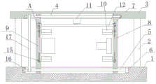
Fig. 1 is a schematic structural diagram of a fixture device for assembling a permanent magnet motor according to the present invention;
fig. 2 is a side view of a fixture device for assembling a permanent magnet motor according to the present invention;
fig. 3 is a schematic structural diagram of a part a of a fixture device for assembling a permanent magnet motor according to the present invention.
In the figure: the device comprises a base 1, a supporting plate 2, a top plate 3, a sliding groove 4, a bidirectional screw 5, a motor 6, a moving plate 7, a moving groove 8, a rotating rod 9, an arc-shaped clamping plate 10, an air cylinder 11, a moving rod 12, a screw groove 13, a positioning rod 14, a moving block 15, a belt pulley 16 and a belt 17.
Detailed Description
The technical solutions in the embodiments of the present invention will be described clearly and completely with reference to the accompanying drawings in the embodiments of the present invention, and it is obvious that the described embodiments are only some embodiments of the present invention, not all embodiments.
Example 1
Referring to fig. 1-3, a clamping apparatus for permanent magnet motor assembly comprises a base 1, two symmetrically arranged support plates 2 are fixedly mounted on the top of the base 1, the same top plate 3 is fixedly mounted on the top of the two support plates 2, sliding grooves 4 are respectively formed in the top of the base 1 and the bottom of the top plate 3, two-way screws 5 are rotatably connected in the sliding grooves 4, a motor 6 is fixedly mounted on the inner wall of one side of one sliding groove 4 of the two sliding grooves 4, the output shaft of the motor 6 is fixedly connected with one two-way screw 5 of the two-way screws 5, the two-way screws 5 are in transmission connection, two symmetrically arranged moving plates 7 are sleeved on the two-way screws 5 in a threaded manner, moving grooves 8 are respectively formed in the mutually close sides of the two moving plates 7, a rotating rod 9 is rotatably connected on the inner wall of the moving groove 8, two symmetrically arranged moving, an arc-shaped clamping plate 10 is fixedly installed on one side of a moving block 15, an air cylinder 11 is fixedly installed at the bottom of the top plate 3, a moving rod 12 is fixedly installed on a piston of the air cylinder 11, and the moving rod 12 is in sliding connection with the two rotating rods 9.
The utility model discloses in, the equal fixed cover in outside of two-way screw rod 5 is equipped with belt pulley 16, and transmission connection has same belt 17 on two belt pulleys 16.
The utility model discloses in, the thread groove 13 that two symmetries set up is seted up in the outside of bull stick 9, and the inboard fixed mounting of movable block has the locating piece, locating piece and the 13 sliding connection of thread groove that corresponds.
In the utility model, the inner side of the moving rod 12 is fixedly provided with a positioning rod 14, and the positioning rod 14 is connected with the corresponding thread groove 13 in a sliding way.
The utility model discloses in, all seted up on the both sides inner wall of sliding tray 4 and rotated the groove, fixed mounting has the outer lane of bearing, the inner circle and the 5 fixed connection of two-way screw rod of bearing on the inner wall in rotation groove.
Example 2
Referring to fig. 1-3, a fixture device for permanent magnet motor assembly comprises a base 1, two symmetrically arranged support plates 2 welded on the top of the base 1, a same top plate 3 welded on the top of the two support plates 2, sliding grooves 4 formed on the top of the base 1 and the bottom of the top plate 3, two-way screws 5 rotatably connected in the sliding grooves 4, a motor 6 welded on the inner wall of one side of one sliding groove 4 of the two sliding grooves 4, an output shaft of the motor 6 fixedly connected with one two-way screw 5 of the two-way screws 5, the two-way screws 5 in transmission connection, two symmetrically arranged moving plates 7 sleeved on the two-way screws 5 in a threaded manner, a moving groove 8 formed on the side of the two moving plates 7 close to each other, a rotating rod 9 rotatably connected on the inner wall of the moving groove 8, two symmetrically arranged moving blocks 15 slidably connected on the rotating rod, an arc-shaped clamping plate 10 is welded on one side of a moving block 15, an air cylinder 11 is welded at the bottom of the top plate 3, a moving rod 12 is welded on a piston of the air cylinder 11, and the moving rod 12 is connected with the two rotating rods 9 in a sliding mode.
The utility model discloses in, the fixed cover in the outside of two-way screw rods 5 is equipped with the belt pulley, and transmission connection has same belt 17 on two belt pulleys 16, and pivoted two-way screw rod 5 can be connected the rotation that drives another two-way screw rod 5 through the transmission of belt pulley 16 and belt 17.
The utility model discloses in, the thread groove 13 that two symmetries set up is seted up in the outside of bull stick 9, and the inboard welding of movable block has the locating piece, locating piece and the 13 sliding connection of corresponding thread groove, and pivoted bull stick 9 can drive the movable block through the sliding connection of locating piece and thread groove 13 and remove.
The utility model discloses in, the inboard welding of carriage release lever 12 has locating lever 14, locating lever 14 and the thread groove 13 sliding connection who corresponds, and the carriage release lever of removal can drive bull stick 9 through locating lever 14 and thread groove 13's sliding connection and rotate.
The utility model discloses in, all seted up on the both sides inner wall of sliding tray 4 and rotated the groove, rotated the outer lane that the welding has the bearing on the inner wall in groove, the inner circle and the 5 fixed connection of two-way screw rod of bearing, the rotation state of two-way screw rod 5 can be stabilized to the bearing.
In the utility model, the cylinder 11 switch is started, the piston of the cylinder 11 drives the moving rod 12 to move, the moving rod 12 can drive the rotating rod 9 to rotate due to the sliding connection of the positioning rod 14 and the thread groove 13, the rotating rod 9 can drive the moving block to move due to the sliding connection of the positioning block and the thread groove 13, the moving block drives the two arc-shaped clamping plates 10 to approach each other, the two arc-shaped clamping plates 10 which are close to each other can clamp the rotor and the stator on the permanent magnet motor, the motor 6 is provided with a power switch, the switch of the motor 6 is opened, the output shaft of the motor 6 drives the two-way screw 5 to rotate, the two-way screw 5 can drive the other two-way screw 5 to rotate due to the transmission connection of the two belt pulleys 16 and the belt 17, the two-way screw 5 can drive the two moving plates 7 to approach each other, and further drive the rotor and the, thereby enabling the rotor and the stator to be fitted.
The above, only be the concrete implementation of the preferred embodiment of the present invention, but the protection scope of the present invention is not limited thereto, and any person skilled in the art is in the technical scope of the present invention, according to the technical solution of the present invention and the utility model, the concept of which is equivalent to replace or change, should be covered within the protection scope of the present invention.
Claims (5)
1. A clamp device for permanent magnet motor assembly comprises a base (1) and is characterized in that two symmetrically arranged support plates (2) are fixedly mounted at the top of the base (1), the same top plate (3) is fixedly mounted at the tops of the two support plates (2), sliding grooves (4) are formed in the tops of the base (1) and the bottom of the top plate (3), two-way screws (5) are rotatably connected in the sliding grooves (4), a motor (6) is fixedly mounted on the inner wall of one side of one sliding groove (4) in the two sliding grooves (4), an output shaft of the motor (6) is fixedly connected with one two-way screw (5) in the two-way screws (5), the two-way screws (5) are in transmission connection, two symmetrically arranged movable plates (7) are sleeved on the two-way screws (5) in a threaded manner, and a movable groove (8) is formed in one side, close to each other, of, the inner wall of the moving groove (8) is rotatably connected with a rotating rod (9), the rotating rod (9) is slidably connected with two moving blocks (15) which are symmetrically arranged, one side of each moving block (15) is fixedly provided with an arc-shaped clamping plate (10), the bottom of the top plate (3) is fixedly provided with an air cylinder (11), a piston of the air cylinder (11) is fixedly provided with a moving rod (12), and the moving rod (12) is slidably connected with the two rotating rods (9).
2. The fixture device for assembling a permanent magnet motor according to claim 1, wherein the two bidirectional screws (5) are fixedly sleeved with belt pulleys (16) on the outer sides, and the same belt (17) is in transmission connection with the two belt pulleys (16).
3. The fixture device for assembling the permanent magnet motor according to claim 1, wherein two symmetrically arranged thread grooves (13) are formed in the outer side of the rotating rod (9), a positioning block is fixedly mounted on the inner side of the moving block, and the positioning block is slidably connected with the corresponding thread groove (13).
4. The fixture device for assembling a permanent magnet motor according to claim 1, wherein a positioning rod (14) is fixedly installed on the inner side of the moving rod (12), and the positioning rod (14) is slidably connected with the corresponding thread groove (13).
5. The fixture device for assembling the permanent magnet motor according to claim 1, wherein the inner walls of the two sides of the sliding groove (4) are both provided with a rotating groove, the inner wall of the rotating groove is fixedly provided with an outer ring of a bearing, and the inner ring of the bearing is fixedly connected with the bidirectional screw (5).
Priority Applications (1)
| Application Number | Priority Date | Filing Date | Title |
|---|---|---|---|
| CN201922265637.4U CN210807030U (en) | 2019-12-17 | 2019-12-17 | A fixture device for permanent-magnet machine assembly |
Applications Claiming Priority (1)
| Application Number | Priority Date | Filing Date | Title |
|---|---|---|---|
| CN201922265637.4U CN210807030U (en) | 2019-12-17 | 2019-12-17 | A fixture device for permanent-magnet machine assembly |
Publications (1)
| Publication Number | Publication Date |
|---|---|
| CN210807030U true CN210807030U (en) | 2020-06-19 |
Family
ID=71226678
Family Applications (1)
| Application Number | Title | Priority Date | Filing Date |
|---|---|---|---|
| CN201922265637.4U Active CN210807030U (en) | 2019-12-17 | 2019-12-17 | A fixture device for permanent-magnet machine assembly |
Country Status (1)
| Country | Link |
|---|---|
| CN (1) | CN210807030U (en) |
Cited By (4)
| Publication number | Priority date | Publication date | Assignee | Title |
|---|---|---|---|---|
| CN112223205A (en) * | 2020-08-28 | 2021-01-15 | 西安航天精密机电研究所 | Rotor dismounting device |
| CN112524418A (en) * | 2020-12-01 | 2021-03-19 | 深圳市意达亨科技有限公司 | Spliced outdoor advertising machine with strip-shaped display screen |
| CN114094780A (en) * | 2021-12-02 | 2022-02-25 | 安徽智鸥驱动科技有限公司 | Mounting fixture and mounting method for permanent magnet of outer rotor brushless motor |
| CN114838870A (en) * | 2022-04-24 | 2022-08-02 | 南京高崎电机有限公司 | Motor testing tool and using method thereof |
-
2019
- 2019-12-17 CN CN201922265637.4U patent/CN210807030U/en active Active
Cited By (5)
| Publication number | Priority date | Publication date | Assignee | Title |
|---|---|---|---|---|
| CN112223205A (en) * | 2020-08-28 | 2021-01-15 | 西安航天精密机电研究所 | Rotor dismounting device |
| CN112524418A (en) * | 2020-12-01 | 2021-03-19 | 深圳市意达亨科技有限公司 | Spliced outdoor advertising machine with strip-shaped display screen |
| CN112524418B (en) * | 2020-12-01 | 2022-04-26 | 深圳市意达亨科技有限公司 | Spliced outdoor advertising machine with strip-shaped display screen |
| CN114094780A (en) * | 2021-12-02 | 2022-02-25 | 安徽智鸥驱动科技有限公司 | Mounting fixture and mounting method for permanent magnet of outer rotor brushless motor |
| CN114838870A (en) * | 2022-04-24 | 2022-08-02 | 南京高崎电机有限公司 | Motor testing tool and using method thereof |
Similar Documents
| Publication | Publication Date | Title |
|---|---|---|
| CN210807030U (en) | A fixture device for permanent-magnet machine assembly | |
| CN218335672U (en) | Assembling device for motor stator and rotor | |
| CN216543167U (en) | Assembly workbench for turntable bearing | |
| CN210575341U (en) | Automatic magnetizing device | |
| CN201698005U (en) | DD motor test bed | |
| CN201685116U (en) | Turnover fixture for drilling and tapping on reducer housing | |
| CN211193000U (en) | Machining clamp capable of clamping rapidly | |
| CN214721431U (en) | Laser welding machine for outer shell of electric wall-hanging furnace | |
| CN221134918U (en) | Multidirectional fixing tool for motor seat machining | |
| CN211148616U (en) | Ammonia nitrogen water quality monitoring box | |
| CN207823775U (en) | A kind of Working piece positioning device of iron frame punching machine for processing | |
| CN214626725U (en) | Coil unwinder | |
| CN220381254U (en) | Aging test stand convenient for fixing and dismounting magneto | |
| CN217776118U (en) | Electrical engineering and automatic positioning and mounting device thereof | |
| CN217860888U (en) | Permanent magnet motor casing adds clamping apparatus | |
| CN220179097U (en) | Motor casing adds clamping apparatus that can accurate adjustment | |
| CN220373108U (en) | Support device for magnetic suspension bearing | |
| CN218504229U (en) | Circular parts processing chucking device for train | |
| CN220944227U (en) | Omnibearing finish machining positioning and fixing device for numerical control machining center | |
| CN218301172U (en) | Motor stator and rotor assembling mechanism | |
| CN214517970U (en) | A high-efficient chamfer device for mould steel | |
| CN220074514U (en) | Sensor part clamping jig | |
| CN219162177U (en) | Automatic motor rotor detection equipment | |
| CN220407169U (en) | Duplex position burring workstation | |
| CN219787946U (en) | Automatic positioning fixture for motor stator polishing |
Legal Events
| Date | Code | Title | Description |
|---|---|---|---|
| GR01 | Patent grant | ||
| GR01 | Patent grant |