CN210790955U - Transfer robot control system cultivated in a pot - Google Patents
Transfer robot control system cultivated in a pot Download PDFInfo
- Publication number
- CN210790955U CN210790955U CN201921850640.6U CN201921850640U CN210790955U CN 210790955 U CN210790955 U CN 210790955U CN 201921850640 U CN201921850640 U CN 201921850640U CN 210790955 U CN210790955 U CN 210790955U
- Authority
- CN
- China
- Prior art keywords
- steering wheel
- steering
- bottom plate
- steering engine
- support column
- Prior art date
- Legal status (The legal status is an assumption and is not a legal conclusion. Google has not performed a legal analysis and makes no representation as to the accuracy of the status listed.)
- Expired - Fee Related
Links
Images


Landscapes
- Manipulator (AREA)
Abstract
The utility model discloses a transfer robot control system cultivated in a pot, including removing the base, installing cloud platform on removing the base, installing arm on the cloud platform, installing gripper and the host system that stretches out the end at the arm, the cloud platform includes steering wheel and drives steering wheel level pivoted steering wheel A, the arm includes first support column, second support column, steering wheel B, steering wheel C and steering wheel D, and the gripper includes mounting bracket and the arc clamping piece of being connected with steering wheel D, still is equipped with camera and tracking module on the bottom plate. The utility model discloses a cloud platform, arm, gripper and the host system that sets up, accessible host system control arm drive gripper conveniently snatch cultivated in a pot, then through installing the tracking module on the bottom plate, can be accurate will carry the robot cultivated in a pot to remove to the target area, simultaneously through the machine vision module that the camera is connected, can judge cultivated in a pot, make cultivated in a pot can put into corresponding target area.
Description
Technical Field
The utility model relates to an agricultural contest robot field especially relates to a transfer robot control system cultivated in a pot.
Background
With the development of agricultural machine intellectualization, more and more workers can be replaced by robots, and a method for checking whether the robots accord with agriculture is judged through a robot challenge match, the existing robot challenge match is generally in an independent match field, a robot departure area, an initial placement area and a transfer target area are arranged in the match field, a guide line is further arranged to connect the initial placement area and the plurality of transfer target areas, reference is provided for the advancing route of the robots, the robots need to be controlled to move potted plants from the initial placement area to the transfer target area when the potted plants are checked, and the performances of the potted plants are judged through the completion time and precision.
The existing transfer robot needs to move in a reciprocating mode when moving, so that the time for transferring potted plants is prolonged, and the transfer efficiency of potted plants is low. In addition, the type of potted plant is difficult to distinguish when the existing potted plant is transported.
Disclosure of Invention
An object of the utility model is to provide a transfer robot control system cultivated in a pot of high and classifiable of transfer efficiency.
The utility model aims at realizing through the following technical scheme:
a potted plant transfer robot control system comprises a moving base, a holder arranged on the moving base, a mechanical arm arranged on the holder, a mechanical claw arranged at the extending end of the mechanical arm and a main control module, wherein the moving base comprises a bottom plate and a plurality of omnidirectional wheels driving the bottom plate to move, a motor with a controller and used for driving each omnidirectional wheel to move is arranged on the bottom plate, the holder is arranged in the middle of the bottom plate and comprises a steering wheel and a steering engine A with a controller and used for driving the steering wheel to horizontally rotate, the steering wheel is rotatably arranged above the bottom plate through a bearing, an installation hole for installing the steering engine A is processed in the middle of the bottom plate, an output shaft of the steering engine A is connected with the steering wheel, the mechanical arm is arranged on the surface of the steering wheel, the mechanical arm comprises a first support column, a second support column, a steering engine B, a steering engine C and a steering engine D, and the steering, the utility model discloses a steering wheel, including first support column and second support, the tip that first support column and second supported is articulated through steering wheel C, and the one end that steering wheel C was kept away from to first support column articulates on the steering wheel through steering wheel B, and the one end that steering wheel C was kept away from to the second support column is passed through steering wheel D and is connected with the gripper, the gripper includes the mounting bracket of being connected with steering wheel D and along the arc clamping piece on the mounting bracket central line symmetry hinge mounting bracket, and processing has intermeshing's tooth on the lateral wall that two arc clamping pieces are relative, be equipped with the steering wheel E that has the controller that drives the arc clamping piece and open and shut in the mounting bracket, motor, steering wheel A, steering wheel B, steering wheel C, steering wheel D and steering wheel E all are connected with host system, still be equipped with the tracking module.
And a machine vision module is arranged in the main control module and is used for processing images shot by the camera.
The tracking module comprises at least two gray sensors and a photoelectric switch, the gray sensors are used for detecting the ground guide line, and the photoelectric switch is used for detecting the potting position.
And a pressure sensor for detecting the clamping of the mechanical claw is arranged on the inner side of the arc-shaped clamping piece, and the pressure sensor is connected with the main control module.
The bottom plate is provided with a plurality of object placing areas which are defined by a plurality of baffle plates.
The utility model discloses has following effect:
(1) through the arranged cloud deck, the mechanical arm, the mechanical claw and the main control module, the mechanical arm can be controlled by the main control module to drive the mechanical claw to conveniently grab the potted plant, then the robot carrying the potted plant can be accurately moved to a target area through the tracking module arranged on the bottom plate, and meanwhile, the potted plant can be judged through the machine vision module connected with the camera, so that the potted plant can be placed in the corresponding target area;
(2) the omnidirectional wheels are started and stopped according to signals output by the main control module by arranging the plurality of annular omnidirectional wheels on the bottom plate and installing the motor for driving the omnidirectional wheels to move and the driver for controlling the motor to work on the bottom plate;
(3) through the arrangement of the steering engines connected with the main control module, the mechanical arm can drive the mechanical claw to perform complex actions in a working plane by matching with the holder, so that the grabbing range of the mechanical claw is increased, and the grabbing efficiency is improved;
(4) the thin film pressure sensor is arranged on the inner wall of the arc-shaped clamping piece, so that the potted plant is prevented from being crushed by the arc-shaped clamping piece due to overlarge pressure;
(5) through setting up a plurality of objects of putting on the bottom plate, make the disposable many basins of transferable of robot cultivated in a pot, improved the efficiency of transfer cultivated in a pot.
Drawings
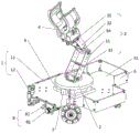
Fig. 1 is a schematic structural diagram of the present invention.
Fig. 2 is a schematic connection diagram of the main control module of the present invention.
Fig. 3 is an exploded view of the cradle head of the present invention.
Fig. 4 is a schematic structural view of the gripper of the present invention.
Figure 5 is a top view of the racetrack.
Reference numerals: 1. moving the base; 11. a base plate; 12. an omni wheel; 13. a motor; 2. a holder; 21. a steering engine A; 22. a rudder wheel; 23. a bearing; 24. mounting holes; 3. a mechanical arm; 31. a first support column; 32. a second support column; 33. a steering engine B; 34. a steering engine C; 35. a steering engine D; 4. a gripper; 41. a mounting frame; 42. an arc-shaped clamping piece; 43. teeth; 44. a steering engine E; 45. a pressure sensor; 5. a baffle plate; 51. a material placing area; 6. a main control module; 61. a machine vision module; 7. a camera; 8. a tracking module; 81. a grayscale sensor; 82. a photoelectric switch; 91. a departure area; 92. an initial placement area; 93. a transfer target area; 94. a guide wire.
Detailed Description
Examples
As shown in fig. 1 to 4, the potted plant transfer robot control system provided in this embodiment includes a mobile base 1, a pan tilt 2 mounted on the mobile base 1, a mechanical arm 3 mounted on the pan tilt 2, a mechanical claw 4 mounted at an extending end of the mechanical arm 3, and a main control module 6 mounted on the mobile base 1, where the mobile base 1 includes a bottom plate 11 and a plurality of omni wheels 12 driving the bottom plate 11 to move, a motor 13 provided with a controller and driving each omni wheel 12 to move is provided on the bottom plate 11, the pan tilt 2 is mounted in the middle of the bottom plate 11, the pan tilt 2 includes a steering wheel 22 and a steering engine a21 provided with a controller and driving the steering wheel 22 to horizontally rotate, the steering wheel 22 is rotatably mounted above the bottom plate 11 through a bearing 23, a mounting hole 24 provided with a steering engine a21 is processed in the middle of the bottom plate 11, an output shaft of the steering engine a21 is connected to the steering wheel 22, the mechanical arm 3 comprises a first support column 31, a second support column 32, a steering engine B33, a steering engine C34 and a steering engine D35, wherein controllers are respectively arranged on the steering engine B33, the steering engine C34 and the steering engine D35, the end parts of the first support column 31 and the second support are hinged through a steering engine C34, one end, far away from the steering engine C34, of the first support column 31 is hinged to a steering wheel 22 through a steering engine B33, one end, far away from the steering engine C34, of the second support column 32 is connected with a mechanical claw 4 through a steering engine D35, the mechanical claw 4 comprises an installation frame 41 connected with the steering engine D35 and arc-shaped clamping members 42 symmetrically hinged to the installation frame 41 along the center line of the installation frame 41, mutually meshed teeth 43 are processed on the side walls opposite to the two arc-shaped clamping members 42, a steering engine E44 with a controller for driving the arc-shaped clamping members 42 to open and close is arranged in the installation frame, the pressure sensor 45 is connected with the main control module 6, the motor 13, the steering engine A21, the steering engine B33, the steering engine C34, the steering engine D35 and the steering engine E44 are connected with the main control module 6, the connection mode adopts the existing and mature connection method, the main control module 6 adopts an STM32F1 series chip control module, preferably an STM32F103 chip control module, the bottom plate 11 is further provided with a tracking module 8 which is connected with the main control module 6 and used for searching potted plant cameras 7 and searching lines for the mobile base 1, images shot by the cameras 7 are transmitted to the main control module 6 and are processed by a machine vision module 61 in the main control module, the machine vision module 61 identifies the type of potted plant through the existing OpenMV, and the main control module 6 drives the mechanical claw 4 to grab the potted plant through the mechanical arm 3 after identification is completed. The tracking module 8 comprises a plurality of gray sensors 81 which are arranged on the bottom surface of the bottom plate 11 and used for detecting the guide line 94 and a photoelectric switch 82 used for detecting the potting position, two gray sensors 81 are arranged at each end of the bottom plate 11, the distance between the two gray sensors 81 is equal to the width of the guide line, the guide line 94 position on the ground is detected by the gray sensors 81 to provide a path reference for the movement of the robot, the number of the gray sensors 81 can be increased, the more the number of the gray sensors 81 is, the more the robot moves more accurately, and the photoelectric switch 82 detects that the main control module 6 controls the robot to stop after potting. The bottom plate 11 is provided with a plurality of object placing areas 51 which are defined by a plurality of baffle plates 5, the bottom plate 11 is also provided with a power supply for providing energy for the robot, and the program for controlling the rotation of the mechanical arm by the main control module 6 is mature in the field of the prior art.
The utility model discloses a use method is:
as shown in fig. 5, when in use, the grayscale sensor 81 detects the position of the guide line 94 and sends the detected data to the main control module 6, the main control module 6 drives the motor 13 through the corresponding driver 14 according to the data fed back by the grayscale sensor 81, the motor 13 drives the omni-directional wheel 12 to rotate for controlling the mobile base 1 to move from the departure area 91 to the initial placement area 92 along the guide line 94, if the grayscale sensor 81 does not detect the position of the guide line 94, the main control module 6 controls the motor 13 through the driver 14 to drive the omni-directional wheel 12 to rotate for swinging the mobile base 1, when the photoelectric switch 82 on the mobile base 1 detects a potting, the main control module 6 stops the motor 13 through the driver 14 according to a preset program for stopping the mobile base 1, and then the camera 7 shoots the shape of the potting and sends the shot image to the main control module 6, the potted plant type is judged through the machine vision module 61 on the main control module 6, and then the main control module 6 controls the linkage of steering engine A21, steering engine B33, steering engine C34, steering engine D35 and steering engine E44, during the linkage: the steering engine A21 drives the steering wheel 22 to rotate horizontally, so that the extending direction of the mechanical arm 3 is aligned with the potted plant, then the steering engine B33 and the steering engine C34 drive the first supporting column 31 and the second supporting column 32 to rotate, so as to drive the mechanical claw 4 mounted on the mechanical arm 3 to move towards the potted plant, the steering engine D35 is used for controlling the mechanical claw 4 to be horizontal with the ground, so as to prevent the arc-shaped clamping piece 42 from colliding with the ground, at the moment, the mechanical claw 4 is in an open state, when the camera 7 shoots the potted plant between the two arc-shaped clamping pieces 42, the steering engine E44 drives the two arc-shaped clamping pieces 42 to rotate along the hinged part through the teeth 43, so as to clamp the potted plant, after the potted plant is clamped, the pressure sensor 45 mounted on the arc-shaped clamping piece 42 detects the force of the potted plant, so as to prevent the potted plant from, at this moment, the mechanical claw 4 clamps the potted plant and then places the potted plant in the corresponding placing area 51, the placing area 51 is classified in advance according to the programmed program, then the main control module 6 repeats the steps to drive the movable base 1 to move, after the potting clamping of the placing area 51 is completed, the main control module 6 drives the movable base 1 to face the transfer target area 93, the potted plant on the placing area 51 is placed in the corresponding target area through the cradle head 2, the mechanical arm 3 and the mechanical claw 4 according to the preset program, and finally the steps are repeated until the potting transfer is completed.
Because the movable base 1 moves through the omnidirectional wheels 12, the movable base 1 can be translated on the competition field, so that the relative position of the movable base 1 can be ensured, and the programming difficulty of the main control module 6 is reduced.
The above description is only a preferred embodiment of the present invention, but the protection scope of the present invention is not limited thereto, and any modification and replacement based on the technical solution and inventive concept provided by the present invention should be covered within the protection scope of the present invention.
Claims (5)
1. The utility model provides a transfer robot control system cultivated in a pot which characterized in that: the device comprises a movable base, a pan-tilt, mechanical arms, mechanical claws and a main control module, wherein the movable base comprises a bottom plate and a plurality of omnidirectional wheels driving the bottom plate to move, a motor driving each omnidirectional wheel to move and provided with a controller is arranged on the bottom plate, the pan-tilt is arranged in the middle of the bottom plate and comprises a steering wheel and a steering engine A with a controller driving the steering wheel to horizontally rotate, the steering wheel is rotatably arranged above the bottom plate through a bearing, a mounting hole for mounting the steering engine A is processed in the middle of the bottom plate, an output shaft of the steering engine A is connected with the steering wheel, the mechanical arms are arranged on the surface of the steering wheel, the mechanical arms comprise a first support column, a second support column, a steering engine B, a steering engine C and a steering engine D, the controllers are arranged on the steering engine B, the ends of the first support column and the second support column are hinged through the steering engine C, one end of the first support column, which, one end of the second support column, far away from the steering gear C, is connected with the gripper through the steering gear D, the gripper comprises a mounting frame connected with the steering gear D and arc-shaped clamping pieces symmetrically hinged to the mounting frame along the central line of the mounting frame, mutually meshed teeth are processed on the side walls, opposite to the two arc-shaped clamping pieces, of the mounting frame, a steering gear E which drives the arc-shaped clamping pieces to open and close and is provided with a controller is arranged in the mounting frame, a motor, a steering gear A, a steering gear B, the steering gear C, the steering gear D and the steering gear E are all connected with a main control module, and a tracking module which is connected with the main control module and used for.
2. A potted plant transfer robot control system as defined in claim 1 wherein: and a machine vision module is arranged in the main control module.
3. A potted plant transfer robot control system as defined in claim 1 wherein: the tracking module comprises at least two gray level sensors and a photoelectric switch.
4. A potted plant transfer robot control system as defined in claim 1 wherein: and a pressure sensor for detecting the clamping of the mechanical claw is arranged on the inner side of the arc-shaped clamping piece, and the pressure sensor is connected with the main control module.
5. A potted plant transfer robot control system as defined in claim 1 wherein: the bottom plate is provided with a plurality of object placing areas which are defined by a plurality of baffle plates.
Priority Applications (1)
| Application Number | Priority Date | Filing Date | Title |
|---|---|---|---|
| CN201921850640.6U CN210790955U (en) | 2019-10-29 | 2019-10-29 | Transfer robot control system cultivated in a pot |
Applications Claiming Priority (1)
| Application Number | Priority Date | Filing Date | Title |
|---|---|---|---|
| CN201921850640.6U CN210790955U (en) | 2019-10-29 | 2019-10-29 | Transfer robot control system cultivated in a pot |
Publications (1)
| Publication Number | Publication Date |
|---|---|
| CN210790955U true CN210790955U (en) | 2020-06-19 |
Family
ID=71238910
Family Applications (1)
| Application Number | Title | Priority Date | Filing Date |
|---|---|---|---|
| CN201921850640.6U Expired - Fee Related CN210790955U (en) | 2019-10-29 | 2019-10-29 | Transfer robot control system cultivated in a pot |
Country Status (1)
| Country | Link |
|---|---|
| CN (1) | CN210790955U (en) |
Cited By (4)
| Publication number | Priority date | Publication date | Assignee | Title |
|---|---|---|---|---|
| CN112871682A (en) * | 2020-12-08 | 2021-06-01 | 梅卡曼德(上海)机器人科技有限公司 | Express delivery package supply system, method, equipment and storage medium |
| CN113600499A (en) * | 2021-07-14 | 2021-11-05 | 中北大学 | Siraitia grosvenorii sorting robot |
| CN115946119A (en) * | 2023-01-04 | 2023-04-11 | 北京化工大学 | Intelligent transportation robot capable of realizing all-dimensional automatic diameter inspection and multi-degree-of-freedom grabbing and placing |
| TWI832536B (en) * | 2021-11-08 | 2024-02-11 | 美商尼奧西斯股份有限公司 | A robot system and related methods of operating and forming a robot system |
-
2019
- 2019-10-29 CN CN201921850640.6U patent/CN210790955U/en not_active Expired - Fee Related
Cited By (5)
| Publication number | Priority date | Publication date | Assignee | Title |
|---|---|---|---|---|
| CN112871682A (en) * | 2020-12-08 | 2021-06-01 | 梅卡曼德(上海)机器人科技有限公司 | Express delivery package supply system, method, equipment and storage medium |
| CN113600499A (en) * | 2021-07-14 | 2021-11-05 | 中北大学 | Siraitia grosvenorii sorting robot |
| TWI832536B (en) * | 2021-11-08 | 2024-02-11 | 美商尼奧西斯股份有限公司 | A robot system and related methods of operating and forming a robot system |
| CN115946119A (en) * | 2023-01-04 | 2023-04-11 | 北京化工大学 | Intelligent transportation robot capable of realizing all-dimensional automatic diameter inspection and multi-degree-of-freedom grabbing and placing |
| CN115946119B (en) * | 2023-01-04 | 2024-06-25 | 北京化工大学 | Intelligent transportation robot capable of realizing omnibearing automatic routing and multi-degree-of-freedom grabbing and placing |
Similar Documents
| Publication | Publication Date | Title |
|---|---|---|
| CN210790955U (en) | Transfer robot control system cultivated in a pot | |
| EP3446951B1 (en) | Working device on inclined surface and cleaning method applied in solar power station | |
| CN204019544U (en) | A kind of running type machine grabbing device | |
| CN101439465B (en) | Cylinder tilter | |
| CN108621119A (en) | A kind of rotation displacement material carrying machine arm and its working method | |
| CN203045155U (en) | Vibrating disc type laser welding tool | |
| CN110092163A (en) | It is a kind of based on the automatic sensing handling device for seeking side centering algorithm | |
| CN105830755B (en) | High branch trimming machinery dynamic counter weight device and control method | |
| CN113232024A (en) | Industrial robot soft object grabbing and identifying device and method | |
| CN206953017U (en) | The full-automatic robot that distributes leaflets | |
| CN112548982A (en) | Automatic transfer robot device and driving method thereof | |
| CN210819533U (en) | Transfer robot cultivated in a pot | |
| CN210850260U (en) | Transfer robot manipulator device and transfer robot | |
| CN104889997A (en) | Solid brewing yeast turning precisely-positioned mechanical hand control system and method | |
| CN207480599U (en) | A kind of motion control device for industrial robot based on machine vision | |
| CN107962054B (en) | Plate replacing method of plate-replaceable operation cleaning robot applied to photovoltaic array | |
| CN205694490U (en) | The dynamic counter weight device of a kind of high branch trimming machinery | |
| CN110178536B (en) | Tomato picking robot and control method thereof | |
| CN209793724U (en) | Series-parallel movable self-balancing heavy-load casting robot | |
| CN110539294A (en) | Transfer robot manipulator device and transfer robot | |
| CN111015367A (en) | Flange locating system based on vision and locating method thereof | |
| CN102962662A (en) | Automatic assembly machine for tail sleeve and check ring | |
| CN212071945U (en) | Storage battery taking and placing device for automobile production line | |
| CN110131571B (en) | Automatic gas filling robot suitable for gas filling places | |
| CN210890769U (en) | Multi-window robot vision positioning device |
Legal Events
| Date | Code | Title | Description |
|---|---|---|---|
| GR01 | Patent grant | ||
| GR01 | Patent grant | ||
| CF01 | Termination of patent right due to non-payment of annual fee |
Granted publication date: 20200619 Termination date: 20201029 |
|
| CF01 | Termination of patent right due to non-payment of annual fee |