CN210779592U - High-efficient heat dissipation cubical switchboard - Google Patents
High-efficient heat dissipation cubical switchboard Download PDFInfo
- Publication number
- CN210779592U CN210779592U CN201921987127.1U CN201921987127U CN210779592U CN 210779592 U CN210779592 U CN 210779592U CN 201921987127 U CN201921987127 U CN 201921987127U CN 210779592 U CN210779592 U CN 210779592U
- Authority
- CN
- China
- Prior art keywords
- switch cabinet
- heat dissipation
- cabinet
- cubical switchboard
- air inlet
- Prior art date
- Legal status (The legal status is an assumption and is not a legal conclusion. Google has not performed a legal analysis and makes no representation as to the accuracy of the status listed.)
- Active
Links
Images

Landscapes
- Patch Boards (AREA)
Abstract
The utility model discloses a high-efficient heat dissipation cubical switchboard, including cubical switchboard, radiator fan and base, radiator fan sets up the top in the cubical switchboard inside, and the base sets up the bottom at the cubical switchboard, and the level is provided with the protection ventilation otter board in the cubical switchboard below radiator fan, and four edges of protection ventilation otter board are provided with the screw rod respectively vertically upwards, and four screw rods all extend to the top of cubical switchboard and outward survey and fix through adjusting nut, and the screw rod is non-contact state with the top of cubical switchboard; the protection ventilation screen plate is characterized in that a plurality of air outlets are correspondingly formed in the cabinet bodies on two sides of the switch cabinet below the protection ventilation screen plate respectively, movable plates are arranged on two sides of the bottom of the protection ventilation screen plate respectively, air holes corresponding to the air outlets are formed in the movable plates, a temperature sensor is arranged on the rear end plate of the cabinet door of the switch cabinet, a display screen is arranged at the front end of the cabinet door of the switch cabinet, and the temperature sensor is connected with the display screen. The utility model discloses can prevent dust and dehumidify and adjust the cubical switchboard interior temperature.
Description
Technical Field
The utility model relates to a high-efficient heat dissipation cubical switchboard belongs to cubical switchboard technical field.
Background
The main function of the switch cabinet is to open and close, control and protect electric equipment in the process of power generation, power transmission, power distribution and electric energy conversion of an electric power system. The cubical switchboard has indoor cubical switchboard and outdoor cubical switchboard, and indoor circulation is not outdoor so good usually, and under the normal atmospheric temperature state, indoor temperature can be higher than outdoor air, is unfavorable for the heat dissipation of cubical switchboard, and for extension electrical components's life, need guarantee according to the season of difference that the temperature maintains in the cubical switchboard in the certain extent. The cubical switchboard structure on the existing market is single, and heat dispersion is poor, and dustproof dehumidification effect is poor.
Disclosure of Invention
For solving prior art's is not enough, the utility model provides a high-efficient heat dissipation cubical switchboard can effectively prevent dust and dehumidify the gas that gets into in the cubical switchboard, and can adjust the heat dissipation of cubical switchboard according to the season of difference, and the temperature is in the certain limit in maintaining the cubical switchboard.
The utility model discloses the technical scheme who adopts does:
a high-efficiency heat dissipation switch cabinet comprises a switch cabinet, a heat dissipation fan and a base, wherein the heat dissipation fan is arranged at the top inside the switch cabinet, the blowing direction is downward, the base is arranged at the bottom of the switch cabinet, a cabinet door of the switch cabinet is arranged at the front end of the switch cabinet, a protective ventilation screen plate is horizontally arranged in the switch cabinet below the heat dissipation fan, four corners of the protective ventilation screen plate are respectively and vertically and upwardly provided with a screw rod, the four screw rods all extend to the outer side of the top of the switch cabinet and are fixed through adjusting nuts, and the screw rods are in a non-contact state with the top of the switch cabinet; a plurality of air outlet holes are correspondingly formed in the cabinet bodies on the two sides of the switch cabinet below the protective ventilation screen plate respectively, movable plates are arranged on the two sides of the bottom of the protective ventilation screen plate respectively and are attached to the cabinet bodies of the switch cabinet on the corresponding sides respectively, air outlet holes corresponding to the air outlet holes are formed in the movable plates, and the height of the bottoms of the movable plates is lower than that of the air outlet hole on the lowest side of the cabinet body on the side edge; a temperature sensor is arranged on the rear end plate of the cabinet door of the switch cabinet, a display screen is arranged at the front end of the cabinet door of the switch cabinet, and the temperature sensor is connected with the display screen; the side that just is to radiator fan has seted up the air inlet duct respectively in the both sides of cubical switchboard, is provided with two rows of air inlet grille from top to bottom on the air inlet duct interior side board, and it has the dust guard to articulate respectively on the cell body of every air inlet grille top and below, and two upper and lower dust guards of same air inlet grille are not close to each other and pass through bolt, nut fixed stay with the fixed one end of cell body, and it has the drier package to fill between two dust guards.
Preferably, the dustproof net is arranged on the outer side of the air inlet groove, and the area of the dustproof net is larger than that of the air inlet groove and is fixed with a cabinet body of the switch cabinet through bolts.
Further preferably, the bottom of the base is provided with a plurality of self-locking universal wheels.
Further preferably, the base is provided with a plurality of vertical heat dissipation holes.
Further preferably, the number of the heat radiation fans is not less than one.
Further preferably, an arc-shaped protective cover is arranged at the top of one end, extending to the outside of the top of the switch cabinet, of the four screw rods.
The beneficial effects of the utility model reside in that:
the dislocation between the air outlet holes and the air holes is adjusted, so that the temperature control in the switch cabinet in different seasons is met; and the air inlet groove is arranged to prevent dust and dehumidify the entering air flow, so that the safety performance is improved.
Drawings
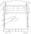
Fig. 1 is a schematic structural view of the present invention;
FIG. 2 is an enlarged view of FIG. 1 at A;
the main reference numerals in the figures have the following meanings:
1. cubical switchboard, 2, radiator fan, 3, base, 4, protection ventilation otter board, 5, screw rod, 6, adjusting nut, 7, venthole, 8, fly leaf, 9, bleeder vent, 10, temperature sensor, 11, display screen, 12, air inlet duct, 13, dust guard, 14, drier package, 15, dust screen, 16, auto-lock universal wheel, 17, louvre, 18, arc protection casing.
Detailed Description
The present invention will be described in detail with reference to the accompanying drawings and examples.
As shown in fig. 1-2: the embodiment is a high-efficiency heat-dissipation switch cabinet, which comprises a switch cabinet 1, a heat-dissipation fan 2 and a base 3, wherein the heat-dissipation fan 2 is arranged at the top inside the switch cabinet 1, the blowing direction is downward, the base 3 is arranged at the bottom of the switch cabinet 1, a cabinet door of the switch cabinet 1 is arranged at the front end of the switch cabinet 1, a protective ventilation screen plate 4 is horizontally arranged in the switch cabinet 1 below the heat-dissipation fan 2, four corners of the protective ventilation screen plate 4 are respectively and vertically and upwardly provided with a screw rod 5, the four screw rods 5 all extend to the outer side of the top of the switch cabinet 1 and are fixed through an adjusting nut 6, and the screw rods 5 and the top of the switch cabinet 1 are in a non; a plurality of air outlets 7 are correspondingly formed on the cabinet bodies on two sides of the switch cabinet 1 below the protection ventilation screen plate 4, movable plates 8 are respectively arranged on two sides of the bottom of the protection ventilation screen plate 4, the movable plates 8 are respectively attached to the cabinet bodies of the switch cabinet 1 on the corresponding sides, air holes 9 corresponding to the air outlets 7 are formed on the movable plates 8, and the bottom height of each movable plate 8 is lower than the height of the air outlet 7 on the lowest side of the cabinet body on the side; a temperature sensor 10 is arranged at the rear end plate of the cabinet door of the switch cabinet 1, a display screen 11 is arranged at the front end of the cabinet door of the switch cabinet, and the temperature sensor 10 is connected with the display screen 11; the side that just is to radiator fan 2 has seted up air inlet duct 12 respectively in cubical switchboard 1's both sides, is provided with two rows of air inlet grille from top to bottom on the air inlet duct 12 interior side plate, has articulated respectively on the cell body of every air inlet grille top and below to have dust guard 13, and two upper and lower dust guards 13 of same air inlet grille are close to each other and pass through bolt, nut fixed stay with the fixed one end of cell body, and it has drier package 14 to fill between two dust guards 13.
Referring to fig. 2, a dust screen 15 is arranged outside the air inlet slot 12, and the area of the dust screen 15 is larger than that of the air inlet slot 12 and is fixed with a cabinet body of the switch cabinet 1 through bolts.
Referring to fig. 1, the bottom of the base 3 is provided with a plurality of self-locking universal wheels 16; the base 3 is also provided with a plurality of vertical heat dissipation holes 17.
In this embodiment, the number of the heat dissipation fans 2 is two.
Referring to fig. 1, an arc-shaped protective cover 18 is arranged on the top of one end of the four screw rods 5 extending to the outside of the top of the switch cabinet 1.
In practical application of the utility model, the temperature sensor 10 detects the temperature in the switch cabinet 1 and transmits the temperature to the display screen 11 for display; because the indoor temperature can be different in different seasons, in actual application, in order to reduce the temperature difference change in the switch cabinet 1, an operator can adjust the relative positions of the air outlet 7 and the air vent 9 according to different seasons; the adjusting mode is as follows: the arc-shaped protective cover 18 is lifted upwards slightly, the movable plate 8 is lifted synchronously, and then the adjusting nut 6 is screwed downwards after the air outlet 7 observes that the rising air holes 9 are staggered for a certain distance from the air outlet 7.
When radiating in cubical switchboard 1, the air current passes through air inlet duct department and gets into in cubical switchboard 1, and dust screen 15 and dust guard 13 and desiccant package 14 can both play certain separation effect to the dust, and moisture in the desiccant package 14 can the absorption air current prevents to produce the influence to the electrical components in cubical switchboard 1.
The above description is only a preferred embodiment of the present invention, and it should be noted that, for those skilled in the art, a plurality of improvements and decorations can be made without departing from the principle of the present invention, and these improvements and decorations should also be regarded as the protection scope of the present invention.
Claims (6)
1. A high-efficiency heat dissipation switch cabinet comprises a switch cabinet (1), a heat dissipation fan (2) and a base (3), and is characterized in that the heat dissipation fan (2) is arranged at the top inside the switch cabinet (1) and the blowing direction is downward, the base (3) is arranged at the bottom of the switch cabinet (1), a cabinet door of the switch cabinet (1) is arranged at the front end of the switch cabinet (1), a protective ventilation screen plate (4) is horizontally arranged in the switch cabinet (1) below the heat dissipation fan (2), four corners of the protective ventilation screen plate (4) are respectively and vertically and upwardly provided with screw rods (5), the four screw rods (5) all extend to the outer side of the top of the switch cabinet (1) and are fixed through adjusting nuts (6), and the screw rods (5) and the top of the switch cabinet (1) are in a non-contact state; a plurality of air outlets (7) are correspondingly formed on the cabinet bodies on two sides of the switch cabinet (1) below the protective ventilation screen plate (4), movable plates (8) are respectively arranged on two sides of the bottom of the protective ventilation screen plate (4), the movable plates (8) are respectively attached to the cabinet bodies of the switch cabinet (1) on the corresponding sides, air holes (9) corresponding to the air outlets (7) are formed in the movable plates (8), and the bottom height of each movable plate (8) is lower than the height of the air outlet (7) on the lowest side of the cabinet body; a temperature sensor (10) is arranged on the rear end plate of the cabinet door of the switch cabinet (1), a display screen (11) is arranged at the front end of the cabinet door of the switch cabinet, and the temperature sensor (10) is connected with the display screen (11); air inlet grooves (12) are formed in the two sides of the switch cabinet (1) and are right opposite to the side edge of the heat dissipation fan (2), two rows of air inlet grids are arranged on an inner side plate of the air inlet grooves (12) from top to bottom, dust-proof plates (13) are hinged to the groove body above and below each air inlet grid respectively, the upper dust-proof plate (13) and the lower dust-proof plate (13) of the same air inlet grid are not close to one end fixed with the groove body and are fixedly supported through bolts and nuts, and drying agent bags (14) are filled between the two dust-proof plates (13).
2. The efficient heat dissipation switch cabinet according to claim 1, wherein a dust screen (15) is arranged outside the air inlet groove (12), and the area of the dust screen (15) is larger than that of the air inlet groove (12) and is fixed with a cabinet body bolt of the switch cabinet (1).
3. An efficient heat dissipation switch cabinet according to claim 1, characterized in that the bottom of the base (3) is provided with a plurality of self-locking universal wheels (16).
4. An efficient heat dissipation switch cabinet according to claim 1, wherein the base (3) is provided with a plurality of vertical heat dissipation holes (17).
5. An efficient heat dissipation switch cabinet according to claim 1, characterized in that the number of the heat dissipation fans (2) is not less than one.
6. An efficient heat dissipation switch cabinet as claimed in claim 1, characterized in that an arc-shaped protective cover (18) is arranged on the top of one end of the four screw rods (5) extending to the outside of the top of the switch cabinet (1).
Priority Applications (1)
| Application Number | Priority Date | Filing Date | Title |
|---|---|---|---|
| CN201921987127.1U CN210779592U (en) | 2019-11-18 | 2019-11-18 | High-efficient heat dissipation cubical switchboard |
Applications Claiming Priority (1)
| Application Number | Priority Date | Filing Date | Title |
|---|---|---|---|
| CN201921987127.1U CN210779592U (en) | 2019-11-18 | 2019-11-18 | High-efficient heat dissipation cubical switchboard |
Publications (1)
| Publication Number | Publication Date |
|---|---|
| CN210779592U true CN210779592U (en) | 2020-06-16 |
Family
ID=71048713
Family Applications (1)
| Application Number | Title | Priority Date | Filing Date |
|---|---|---|---|
| CN201921987127.1U Active CN210779592U (en) | 2019-11-18 | 2019-11-18 | High-efficient heat dissipation cubical switchboard |
Country Status (1)
| Country | Link |
|---|---|
| CN (1) | CN210779592U (en) |
Cited By (1)
| Publication number | Priority date | Publication date | Assignee | Title |
|---|---|---|---|---|
| CN112366559A (en) * | 2020-10-30 | 2021-02-12 | 武汉台顺电气设备有限公司 | Intelligent box-type substation |
-
2019
- 2019-11-18 CN CN201921987127.1U patent/CN210779592U/en active Active
Cited By (1)
| Publication number | Priority date | Publication date | Assignee | Title |
|---|---|---|---|---|
| CN112366559A (en) * | 2020-10-30 | 2021-02-12 | 武汉台顺电气设备有限公司 | Intelligent box-type substation |
Similar Documents
| Publication | Publication Date | Title |
|---|---|---|
| CN206806820U (en) | A kind of stable multifunction power cabinet of damping | |
| CN203839763U (en) | Adjustment heat radiation distribution box | |
| CN106505440A (en) | A kind of power distribution cabinet with moistureproof ventilation function | |
| CN211046128U (en) | Novel distribution box | |
| CN210779592U (en) | High-efficient heat dissipation cubical switchboard | |
| CN210610163U (en) | Electronic information communication base station for power grid | |
| CN213212832U (en) | Switch board with antidetonation support function | |
| CN212411730U (en) | Moisture-proof box-type transformer | |
| CN113097873A (en) | Box-type substation cooling system | |
| CN219180978U (en) | Switch board with circulation dehumidification function | |
| CN219287983U (en) | Air quantity adjustable ventilation device for equipment | |
| CN209608135U (en) | A kind of internal-circulation type high efficiency and heat radiation power distribution cabinet | |
| CN107769002A (en) | A kind of power distribution cabinet with anti-interference function | |
| CN207542633U (en) | A kind of distribution box | |
| CN207149902U (en) | A kind of moistureproof anti-condensation switching station of self-loopa | |
| CN214543288U (en) | High-pressure gas-filled cabinet with drying structure | |
| CN213782693U (en) | Outdoor compensation cabinet with efficient heat dissipation | |
| CN211377283U (en) | Switch board that radiating effect is good | |
| CN203895796U (en) | Improved box-type transformer station | |
| CN204481359U (en) | For the radiator structure of box type transformer | |
| CN221508372U (en) | Energy storage battery cabinet for energy storage transformer substation | |
| CN219513527U (en) | American box transformer device | |
| CN215645679U (en) | Novel electrical equipment monitoring box | |
| CN221264315U (en) | Dampproofing dirt-proof contravariant cabinet | |
| CN209104648U (en) | A kind of safe type intelligent power distribution cabinet |
Legal Events
| Date | Code | Title | Description |
|---|---|---|---|
| GR01 | Patent grant | ||
| GR01 | Patent grant |