CN210779564U - Electrical cabinet with dust removal function - Google Patents
Electrical cabinet with dust removal function Download PDFInfo
- Publication number
- CN210779564U CN210779564U CN201921700677.0U CN201921700677U CN210779564U CN 210779564 U CN210779564 U CN 210779564U CN 201921700677 U CN201921700677 U CN 201921700677U CN 210779564 U CN210779564 U CN 210779564U
- Authority
- CN
- China
- Prior art keywords
- cabinet body
- dust removal
- dust
- cabinet
- removal function
- Prior art date
- Legal status (The legal status is an assumption and is not a legal conclusion. Google has not performed a legal analysis and makes no representation as to the accuracy of the status listed.)
- Active
Links
Images


Abstract
The utility model relates to a regulator cubicle dust collector technical field of environmental protection, and disclose a regulator cubicle with dust removal function, the intelligent cabinet temperature adjusting device comprises a cabinet body, the top fixed mounting of the cabinet body has the baffle, the side of baffle is rotated through the bearing and is connected with the bull stick, and the both ends of bull stick run through the side of baffle and extend to the left and right sides of the cabinet body, two main flabellum and two main pulleys have been cup jointed to the outer disc of bull stick, the right-hand member fixedly connected with crank of bull stick, the left side inner wall of the cabinet body is provided with dust removal mechanism, the left surface of the cabinet body is provided with two ventilative nets, fixed mounting has the baffle between the inside wall of the cabinet body, and the top. The utility model provides a current regulator cubicle utilize electric power dust removal feature of environmental protection poor, maintain very inconvenient to the relatively poor problem of effect of dust clearance collection.
Description
Technical Field
The utility model relates to a regulator cubicle dust collector technical field of environmental protection specifically is a regulator cubicle with dust removal function.
Background
The electrical cabinet is a cabinet which is processed by steel materials and used for protecting components from normally working, has wide application, is mainly used in the chemical industry, the environmental protection industry, the power system, the metallurgical system, the industry, the nuclear power industry, the fire safety monitoring, the traffic industry and the like, and after the electrical cabinet is used for a long time, a large amount of dust is frequently accumulated in the electrical cabinet, so that the normal use of the components is influenced, and the cleaning of the dust is very troublesome and is difficult to clean;
the existing electrical cabinet with the dust removal function is an electrically-driven dust removal device, the device needs workers to perform cleaning work at intervals, even though the device is used for cleaning electric power, the device still needs to be started manually, the maintenance is very inconvenient, electric power dust removal needs to consume electric power resources, the environmental protection performance is poor, the use cost is increased, and the dust collection effect is not obvious when the device is cleaned.
SUMMERY OF THE UTILITY MODEL
Technical problem to be solved
Not enough to prior art, the utility model provides a regulator cubicle with dust removal function has solved current regulator cubicle and has utilized electric power dust removal feature of environmental protection poor, maintains very inconvenient to the relatively poor problem of effect of dust clearance collection.
(II) technical scheme
In order to achieve the above object, the utility model provides a following technical scheme: an electrical cabinet with a dust removal function comprises a cabinet body, wherein a partition plate is fixedly mounted at the top of the cabinet body, a rotating rod is rotatably connected to the side face of the partition plate through a bearing, two ends of the rotating rod penetrate through the side face of the partition plate and extend to the left side and the right side of the cabinet body, two main fan blades and two main belt wheels are sleeved on the outer circular face of the rotating rod, a hand crank is fixedly connected to the right end of the rotating rod, a dust removal mechanism is arranged on the inner wall of the left side of the cabinet body, two breathable nets are arranged on the left side face of the cabinet body, a baffle is fixedly mounted between the inner side wall of the cabinet body, a suction port is formed in the top of the baffle, a dust collection box is fixedly mounted between the bottom of the baffle and the inner bottom wall of the cabinet body, the right side face of the dust collection box is in a through-hole shape, a dust filter net is arranged on the, the first driven belt wheel is in transmission connection with the main belt wheel on the right side through a first belt, the first belt wheel sequentially penetrates through the top of the cabinet body and the top of the baffle, and the left end of the rotating shaft extends into the dust collection box and is fixedly connected with a dust extraction fan;
dust removal mechanism includes three dwang and fender cover, three opening has been seted up to the right flank that keeps off the cover, and the left end of dwang and the left side inner wall of the cabinet body rotate to be connected, the outer disc of dwang has cup jointed the second from the band pulley, and three second from the band pulley with be located and be connected through second belt transmission between the left main band pulley, and the second belt runs through the top of keeping off cover and the cabinet body in proper order, the outer disc of dwang has cup jointed the dust removal fan, and the dust removal fan is located the opening that keeps off the cover.
Preferably, the left side surface of the cabinet body is provided with a vent.
Preferably, the outer circular surface of the rotating rod is movably sleeved with two fixing sleeves, and the fixing sleeves are fixed at the top of the cabinet body.
Preferably, the breathable net is positioned on the left side of the shield.
Preferably, the air outlet direction of the fan blades of the dust extraction fan is opposite to that of the dust removal fan.
Preferably, the air outlet directions of the two main fan blades are opposite, and the two main fan blades are symmetrical by using the partition plate.
(III) advantageous effects
Compared with the prior art, the utility model provides a regulator cubicle with dust removal function possesses following beneficial effect:
1. the utility model discloses a dwang, fender cover, second that set up are from band pulley, second belt and dust removal fan, under the effect that utilizes natural wind, and the dust removal fan rotates and blows the dust of the cabinet body, and the rotation of dirt fan is taken out in the cooperation, collects in timely suction of dust to the dust collecting box that will blow, and the effectual dust that goes on is collected the dust of blowing, has solved the dust after the tradition blows and has wandered the problem of unable effective collection everywhere, the secondary dust of avoiding.
2. The utility model discloses an utilize natural wind as power, the effectual electric power resource that has saved has the feature of environmental protection, the cost of saving to long maintaining, more convenient that need not staff.
3. Through the hand crank that sets up, can realize manual going on to the rotation of bull stick, under some extreme environment, carry out artifical dust removal work in the weather that does not blow, the simple operation also has the feature of environmental protection.
Drawings
Fig. 1 is a front view of an electrical cabinet with a dust removal function according to the present invention;
fig. 2 is a cross-sectional view of an electrical cabinet with a dust removal function according to the present invention;
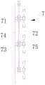
fig. 3 is a cross-sectional view of the dust removing mechanism of the present invention.
In the figure: the dust removal device comprises a cabinet body 1, a partition plate 2, a rotating rod 3, a main fan blade 4, a main belt wheel 5, a hand crank 6, a dust removal mechanism 7, a rotating rod 71, a shield cover 72, a second driven belt wheel 73, a second belt 74, a dust removal fan 75, a ventilation net 8, a baffle plate 9, a dust collection box 10, a dust filtration net 11, a rotating shaft 12, a first driven belt wheel 13, a first belt 14 and a dust extraction fan 15.
Detailed Description
The technical solutions in the embodiments of the present invention will be described clearly and completely with reference to the accompanying drawings in the embodiments of the present invention, and it is obvious that the described embodiments are only some embodiments of the present invention, not all embodiments. Based on the embodiments in the present invention, all other embodiments obtained by a person skilled in the art without creative work belong to the protection scope of the present invention.
As shown in fig. 1-3, the utility model provides a technical solution: an electrical cabinet with a dust removal function comprises a cabinet body 1, wherein a vent hole is formed in the left side surface of the cabinet body 1, a partition plate 2 is fixedly installed at the top of the cabinet body 1, when wind is blown in one direction, the partition plate can shield a main fan blade 4 in the other direction, so that the two main fan blades 4 are prevented from being blown simultaneously and the rotating efficiency is influenced, the side surface of the partition plate 2 is rotatably connected with a rotating rod 3 through a bearing, two ends of the rotating rod 3 penetrate through the side surface of the partition plate 2 and extend to the left side and the right side of the cabinet body 1, two fixing sleeves are movably sleeved on the outer circular surface of the rotating rod 3 and fixed at the top of the cabinet body 1, so that the fixing of the rotating rod 3 can be increased, the stability of the main fan blades 4 during rotation is ensured, the outer circular surface of the rotating rod 3 is sleeved with the two main fan blades 4 and two main belt wheels 5, the fan blade air, the dust collection box can drive the rotating rod 3 to rotate and increase the wind probability, the right end of the rotating rod 3 is fixedly connected with a hand crank 6, the inner wall of the left side of the cabinet body 1 is provided with a dust collection mechanism 7, the left side surface of the cabinet body 1 is provided with two breathable nets 8, the breathable nets 8 are positioned at the left side of the shield cover 72 to ensure the air flow inside the shield cover 72 to circulate, a baffle plate 9 is fixedly installed between the inner side walls of the cabinet body 1, the top of the baffle plate 9 is provided with a suction port, a dust collection box 10 is fixedly installed between the bottom of the baffle plate 9 and the inner bottom wall of the cabinet body 1, the right side surface of the dust collection box 10 is arranged in a through-port shape, the left side surface of the dust collection box 10 is provided with a dust filtration net 11, the inner wall of the right side of the cabinet body 1 is fixedly installed with a rotating shaft 12, the outer circular surface of the rotating shaft 12 is sleeved with a first secondary belt wheel 13, the first secondary belt wheel 13, the left end of the rotating shaft 12 extends into the dust collecting box 10 and is fixedly connected with a dust extraction fan 15, and the air outlet direction of the dust extraction fan 15 is opposite to that of the dust removal fan 75;
The working principle is as follows: during operation, natural wind blows main fan leaf 4, drives bull stick 3 and rotates, through two main band pulleys 5, respectively under the effect of first belt 14 and second belt 74 for pivot 12 and dwang 71 rotate, and three dust removal fan 75 rotates, blows the dust on the electrical components of the cabinet body 1, and the rethread dust extraction fan 15 will float the dust and collect in dust collection box 10, through straining dirt net 11, the air current discharges, and the dust is stayed in dust collection box 10.
It is noted that, herein, relational terms such as first and second, and the like may be used solely to distinguish one entity or action from another entity or action without necessarily requiring or implying any actual such relationship or order between such entities or actions. Also, the terms "comprises," "comprising," or any other variation thereof, are intended to cover a non-exclusive inclusion, such that a process, method, article, or apparatus that comprises a list of elements does not include only those elements but may include other elements not expressly listed or inherent to such process, method, article, or apparatus.
Although embodiments of the present invention have been shown and described, it will be appreciated by those skilled in the art that changes, modifications, substitutions and alterations can be made in these embodiments without departing from the principles and spirit of the invention, the scope of which is defined in the appended claims and their equivalents.
Claims (6)
1. The utility model provides an regulator cubicle with dust removal function, includes cabinet body (1), its characterized in that: the dust collection cabinet is characterized in that a partition plate (2) is fixedly mounted at the top of the cabinet body (1), the side face of the partition plate (2) is rotatably connected with a rotating rod (3) through a bearing, the two ends of the rotating rod (3) penetrate through the side face of the partition plate (2) and extend to the left side and the right side of the cabinet body (1), two main fan blades (4) and two main belt wheels (5) are sleeved on the outer circular face of the rotating rod (3), a hand crank (6) is fixedly connected with the right end of the rotating rod (3), a dust removal mechanism (7) is arranged on the inner wall of the left side of the cabinet body (1), two breathable nets (8) are arranged on the left side face of the cabinet body (1), a baffle plate (9) is fixedly mounted between the inner side walls of the cabinet body (1), a suction port is formed in the top of the baffle plate (9), a dust collection box (10) is fixedly mounted between the bottom of the baffle plate (9, a dust filtering net (11) is arranged on the left side face of the dust collection box (10), a rotating shaft (12) is fixedly mounted on the inner wall of the right side of the cabinet body (1), a first driven belt wheel (13) is sleeved on the outer circular face of the rotating shaft (12), the first driven belt wheel (13) is in transmission connection with the main belt wheel (5) located on the right side through a first belt (14), a first belt (14) wheel sequentially penetrates through the top of the cabinet body (1) and the top of the baffle (9), and the left end of the rotating shaft (12) extends into the dust collection box (10) and is fixedly connected with a dust extraction fan (15);
dust removal mechanism (7) include three dwang (71) and keep off cover (72), three opening has been seted up to the right flank that keeps off cover (72), and the left end of dwang (71) is rotated with the left side inner wall of the cabinet body (1) and is connected, the outer disc of dwang (71) has cup jointed second from band pulley (73), and three second from band pulley (73) and be located between left main band pulley (5) through second belt (74) transmission connection, and second belt (74) run through the top that keeps off cover (72) and cabinet body (1) in proper order, the outer disc of dwang (71) has cup jointed dust removal fan (75), and dust removal fan (75) are located the opening that keeps off cover (72).
2. The electrical cabinet with the dust removal function according to claim 1, wherein: the left side surface of the cabinet body (1) is provided with an air vent.
3. The electrical cabinet with the dust removal function according to claim 1, wherein: two fixed sleeves are movably sleeved on the outer circular surface of the rotating rod (3), and the fixed sleeves are fixed at the top of the cabinet body (1).
4. The electrical cabinet with the dust removal function according to claim 1, wherein: the breathable net (8) is positioned on the left side of the blocking cover (72).
5. The electrical cabinet with the dust removal function according to claim 1, wherein: the air outlet directions of the dust extraction fan (15) and the dust removal fan (75) are opposite.
6. The electrical cabinet with the dust removal function according to claim 1, wherein: the air outlet directions of the two main fan blades (4) are opposite, and the two main fan blades are symmetrical through the partition plate (2).
Priority Applications (1)
| Application Number | Priority Date | Filing Date | Title |
|---|---|---|---|
| CN201921700677.0U CN210779564U (en) | 2019-10-11 | 2019-10-11 | Electrical cabinet with dust removal function |
Applications Claiming Priority (1)
| Application Number | Priority Date | Filing Date | Title |
|---|---|---|---|
| CN201921700677.0U CN210779564U (en) | 2019-10-11 | 2019-10-11 | Electrical cabinet with dust removal function |
Publications (1)
| Publication Number | Publication Date |
|---|---|
| CN210779564U true CN210779564U (en) | 2020-06-16 |
Family
ID=71050563
Family Applications (1)
| Application Number | Title | Priority Date | Filing Date |
|---|---|---|---|
| CN201921700677.0U Active CN210779564U (en) | 2019-10-11 | 2019-10-11 | Electrical cabinet with dust removal function |
Country Status (1)
| Country | Link |
|---|---|
| CN (1) | CN210779564U (en) |
Cited By (1)
| Publication number | Priority date | Publication date | Assignee | Title |
|---|---|---|---|---|
| CN114465096A (en) * | 2021-12-29 | 2022-05-10 | 蚌埠市荣盛金属制品有限公司 | Be applied to electrical cabinet in many wind-blown sand areas |
-
2019
- 2019-10-11 CN CN201921700677.0U patent/CN210779564U/en active Active
Cited By (2)
| Publication number | Priority date | Publication date | Assignee | Title |
|---|---|---|---|---|
| CN114465096A (en) * | 2021-12-29 | 2022-05-10 | 蚌埠市荣盛金属制品有限公司 | Be applied to electrical cabinet in many wind-blown sand areas |
| CN114465096B (en) * | 2021-12-29 | 2023-12-19 | 蚌埠市荣盛金属制品有限公司 | Electrical cabinet applied to windy and sandy zone |
Similar Documents
| Publication | Publication Date | Title |
|---|---|---|
| CN208849303U (en) | It is a kind of with heat sinking function and to facilitate the electric power cabinet of dedusting | |
| CN210779564U (en) | Electrical cabinet with dust removal function | |
| CN213529993U (en) | Cyclone dust collector | |
| CN215637808U (en) | Building engineering is with ventilation dust collector with adjustable | |
| CN213314125U (en) | Air purifying device of marine air conditioner | |
| CN201930664U (en) | Dust collection device with rotary filter disc | |
| CN212487036U (en) | Heat dissipation device for wind driven generator switch | |
| CN210645718U (en) | A dust removal purification pipeline for industrial exhaust handles | |
| CN212360256U (en) | Dustproof axial fan that can clear up automatically | |
| CN213790553U (en) | Coal-bed gas fracturing well row adopts in-process buggy to filter clearing device | |
| CN211885878U (en) | Smoke dust collecting device | |
| CN211562353U (en) | Whole blowing and sucking type dust collector in workshop | |
| CN209978284U (en) | Ventilation unit is used in workshop that suitability is strong | |
| CN218692183U (en) | Complete machine dust removal device for railway signal relay | |
| CN206305169U (en) | A kind of fast dust-removing and the dust treatment plant of energy-conserving and environment-protective | |
| CN219059882U (en) | Exhaust type fallen leaf cleaning machine | |
| CN214106134U (en) | Unpowered centrifugal particulate matter intercepting purifier | |
| CN212417402U (en) | Cutting fluid oil mist water mist processor | |
| CN218924120U (en) | Air-blower oil-gas separation device | |
| CN217511442U (en) | Rotary filtering assembly | |
| CN220750335U (en) | Automatic clean environmental protection ventilation subassembly | |
| CN220050216U (en) | Cutting device with chip cleaning function | |
| CN211143853U (en) | Protection canopy for building safety | |
| CN211635706U (en) | Anti-blocking formula primary filter for filtration | |
| CN218033527U (en) | Automatic cleaning and filtering device in air conditioner ventilation system |
Legal Events
| Date | Code | Title | Description |
|---|---|---|---|
| GR01 | Patent grant | ||
| GR01 | Patent grant |