CN210764160U - Compact lifting combined fork - Google Patents
Compact lifting combined fork Download PDFInfo
- Publication number
- CN210764160U CN210764160U CN201921303869.8U CN201921303869U CN210764160U CN 210764160 U CN210764160 U CN 210764160U CN 201921303869 U CN201921303869 U CN 201921303869U CN 210764160 U CN210764160 U CN 210764160U
- Authority
- CN
- China
- Prior art keywords
- fork
- fixed
- frame structure
- driving
- frame
- Prior art date
- Legal status (The legal status is an assumption and is not a legal conclusion. Google has not performed a legal analysis and makes no representation as to the accuracy of the status listed.)
- Active
Links
Images


Abstract
Compact lift combination fork includes: the fixed base is of a frame structure; four lifting unit locate fixed baseplate frame structure frame four corners respectively, and it includes: the two ends of the rotating shaft penetrate through the fixed base frame structure through the bearing and the bearing seat; one end of the crank is connected with one end of the rotating shaft, which is positioned at the inner side of the fixed base frame structure, and the other end of the crank is provided with a short shaft which is vertical to the axis of the crank relative to the other side surface of the rotating shaft; the guide wheel is arranged on the short shaft; the crane includes: two support rods and a connecting rod connected to the middle parts of the two support rods; two ends of the supporting rod are respectively provided with a fixed frame corresponding to each lifting assembly, and the guide wheel is arranged in the fixed frame; a lift drive mechanism comprising: the driving mechanism comprises a driving shaft, two driving gears, four transmission gears, two driving chains, a driving motor and a speed reducer; the telescopic fork is arranged on the two support rods of the lifting frame; and the lifting driving mechanism driving motor and the telescopic fork are electrically connected with the controller.
Description
Technical Field
The utility model relates to a transportation equipment, in particular to compact lift combination fork is applicable to full-automatic servo load and carry the goods loading and unloading among the automatic handling processes such as machine, shuttle, RGV and AGV.
Background
The full-automatic servo transfer machine is widely applied to intelligent conveying lines, matched adaptive automatic production lines and intelligent material conveying transfer lines are also generated in succession, and how to automatically and effectively take out, place and butt joint goods forms intelligent integrated circulation of automatic goods loading, unloading, conveying, transferring, assembling, warehousing and the like.
At present, in the field of automatic conveying in China, an import fork mechanism is mostly adopted, the price is high, and in addition, research and development design and a shuttle car or AGV butt joint mechanism are needed to realize connection and lifting, the structure is complex, and the bottleneck of overall height hidden danger is obvious.
Disclosure of Invention
An object of the utility model is to design a compact lift combination fork, satisfy the automatic handling and the butt joint of goods on the intelligence production line, will go up and down and two-way transport is integrated integrative.
In order to achieve the above purpose, the technical scheme of the utility model is that:
compact lift combination fork, it includes: the fixed base is of a frame structure, two opposite side frames of the fixed base are respectively composed of two layers of fixed plates, the middle part of each fixed plate is provided with a central hole, and two ends of each fixed plate are respectively provided with an installation through hole; four lifting unit set up respectively in two-layer fixed plate installation through-hole department of fixed baseplate frame structure frame, this lifting unit includes: two ends of the rotating shaft penetrate through the mounting through holes of the two layers of fixing plates of the frame of the fixed base frame structure through a bearing and a bearing seat; one end of the crank is connected with one end of the rotating shaft, which is positioned at the inner side of the fixed base frame structure, and the other side surface of the other end of the crank, which is opposite to the rotating shaft, is provided with a short shaft which is vertical to the axis of the crank; the guide wheel is arranged on the short shaft; a lift drive mechanism comprising: two ends of the driving shaft penetrate through central holes of two layers of fixing plates of the frame of the fixed base frame structure through a bearing and a bearing seat; the two driving gears are respectively arranged at two ends of the driving shaft and are positioned between two layers of fixing plates of the frame of the fixed base frame structure; the four transmission gears are respectively arranged on the rotating shafts of the four lifting assemblies and are positioned between the two layers of fixing plates of the frame of the fixed base frame structure; the two driving chains respectively bypass two driving gears and four transmission gears which are arranged on the two side frames of the fixed base frame structure and are positioned between the two layers of fixed plates of the fixed base frame structure; the driving motor and the speed reducer are arranged outside the frame of the fixed base frame structure, and an output shaft of the speed reducer is connected to one end of the driving shaft; the crane, it includes: two support rods and a connecting rod connected to the middle parts of the two support rods; two ends of the supporting rod are respectively provided with a fixed frame corresponding to each lifting assembly, and the guide wheel is arranged in the fixed frame; the telescopic fork is arranged on the two support rods of the lifting frame; and the lifting driving mechanism driving motor and the telescopic fork are electrically connected with the controller.
Further, still be equipped with straining device, it includes:
guide holes are formed in the middle of two layers of fixing plates of the frame structure of the fixing base corresponding to two sides of the two driving gears;
the four tensioning gears are arranged on two sides of the two driving gears in pairs, and the two driving chains bypass the tensioning gears; two ends of a wheel shaft on the tensioning gear are respectively inserted into the guide holes on the fixing plate; the two ends of the corresponding wheel shaft are respectively arranged on the adjusting screw rods, and the lower parts of the adjusting screw rods are fixed on the fixing plate through fixing blocks.
Preferably, a supporting pulley is respectively arranged on two sides of the fixing frames at two ends of the supporting rod corresponding to the inner side surface of the fixing base frame structure.
Preferably, the telescopic fork adopts a three-level linear differential telescopic fork which mainly comprises an upper fork, a middle fork, a lower fork and a needle roller bearing for guiding, and the upper fork, the middle fork and the lower fork are driven by a motor in a chain transmission mode; the lower fork is a fixed fork and is fixed on the two support rods of the lifting frame.
Preferably, the guide wheel is a rolling bearing.
The lifting frame of the utility model is mainly used for lifting and descending the pallet fork, the lifting mechanism is driven by the crank and the chain, and the driving structure of each side chain is provided with three tensioning mechanisms for solving the asynchronism of each cam, thereby leading the lifting and the descending to be more stable; the telescopic fork is mainly used for taking and placing goods, the fork adopts a three-level linear differential telescopic fork, and comprises an upper fork, a middle fork, a lower fork (a fixed fork), a needle bearing and the like which play a role in guiding, and the fork adopts a chain transmission mode.
The utility model has the advantages that:
the utility model provides a use of flexible fork on full-automatic shuttle or AGV, satisfy the butt joint of the core component fork on shuttle and the AGV. Compared with the prior art, the utility model discloses compact lift combination fork's raw and other materials gain the convenience, and the consumptive material is less, the quality is lighter, the structure is succinct, part preparation process is simple, so, has saved energy, low cost.
Drawings
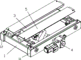
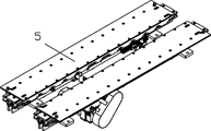
Fig. 1 is a perspective view of an embodiment of the present invention;
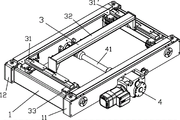
fig. 2 is a perspective view 1 of a lifting drive mechanism in an embodiment of the present invention;
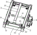
fig. 3 is a perspective view 2 of a lifting driving mechanism in an embodiment of the present invention;
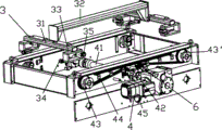
fig. 4 is a perspective view of the lifting driving mechanism in the embodiment of the present invention, fig. 3;
fig. 5 is an exploded perspective view of the lift driving mechanism of the embodiment of the present invention, 1;
fig. 6 is an exploded perspective view of the lift driving mechanism according to the embodiment of the present invention, fig. 2.
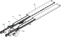
Fig. 7 is a perspective view of a retractable fork according to an embodiment of the present invention;
fig. 8 is an expanded schematic view of the retractable fork according to the embodiment of the present invention.
Detailed Description
Referring to fig. 1-8, the utility model discloses a compact lift combination fork, include:
the fixed base 1 is a frame structure, two opposite side frames 11 and 11' of the fixed base are respectively composed of two layers of fixed plates 111 and 112 (taking the side frame 11 as an example, the same below), the middle parts of the fixed plates 111 and 112 are provided with center holes, and two ends of the fixed plates are respectively provided with an installation through hole;
four lifting unit 2, set up respectively in two-layer fixed plate installation through-hole department of 1 fixed baseplate frame structure frame, this lifting unit 2 (using lifting unit 2 as an example, the same down) includes:
two ends of the rotating shaft 21 penetrate through mounting through holes of two layers of fixing plates of the frame structure frame of the fixing base 1 through bearings and bearing seats;
one end of the crank 22 is connected to one end of the rotating shaft 21 positioned at the inner side of the frame structure of the fixed base 1, and the other end of the crank 22 is provided with a short shaft 221 which is perpendicular to the axis of the crank 22 relative to the other side surface of the rotating shaft 21;
a guide wheel 23 provided on the stub shaft 221;
two support rods 31, 31 'and a connecting rod 32 connected to the middle of the two support rods 31, 31'; two ends of the supporting rod 31 (taking the supporting rod 31 as an example, the same below) are respectively provided with a fixed frame 33 (taking the fixed frame 33 as an example, the same below) corresponding to each lifting assembly 2, and the guide wheel 23 is arranged in the fixed frame 33;
the lift drive mechanism 4 includes:
two ends of the driving shaft 41 penetrate through the central holes of the two layers of fixing plates of the frame structure frame of the fixing base 1 through bearings and bearing seats;
two driving gears 42, 42 'respectively disposed at two ends of the driving shaft 41 and located between two layers of fixing plates 111, 112 of the frame structure 11' of the fixing base 1;
four transmission gears 43, 43 ' (taking the transmission gears 43, 43 ' as an example, the same applies below) respectively arranged on the rotating shafts 21 of the four lifting assemblies 2 and located between two layers of fixing plates 111, 112 of the frame structure frame 11 ' of the fixing base 1;
two driving chains 44, which respectively bypass two driving gears 42, 42 ' and four transmission gears 43, 43 ' arranged between two layers of fixing plates 111, 112 of the frame structure frame 11 ' of the fixing base 1 at the two side frames of the frame structure of the fixing base 1;
the driving motor 45 and the speed reducer are arranged outside the frame structure frame 11' of the fixed base 1, and the output shaft of the speed reducer is connected to one end of the driving shaft 41;
the telescopic fork 5 is arranged on the two support rods 31 and 31' of the lifting frame 3;
and a controller (not shown) to which the lifting driving mechanism driving motor 45 and the telescopic fork 5 are electrically connected.
Further, the utility model discloses still be equipped with straining device 6, it includes:
the middle parts of the two layers of fixing plates 111 and 112 of the frame structure frame 11 'of the fixing base 1 corresponding to the two sides of the two driving gears 42 and 42' are provided with guide holes 1111, 1112, 1121 and 1122;
four tension gears 61, 61 '(taking the tension gears 61, 61' as an example, the same applies below) disposed two by two on both sides of the two driving gears 42, 42 ', the two driving chains 44 passing around the tension gears 61, 61'; the two ends of the wheel shafts 611, 611 'on the tensioning gears 61, 61' are respectively inserted into the guide holes 1111, 1112, 1121, 1122 on the fixing plates 111, 112; the adjusting screws 62, 62 ' (taking the adjusting screws 62, 62 ' as an example, the same applies hereinafter) are respectively disposed at two ends of the corresponding wheel shafts 611, 611 ', and the lower portions of the adjusting screws 62, 62 ' are fixed on the fixing plates 111, 112 through the fixing blocks 63, 63 '.
Preferably, two sides of the fixing frames 33 at two ends of the supporting rod 31 are respectively provided with a supporting pulley 34, 35 corresponding to the inner side surface of the frame structure of the fixed base 1.
Preferably, the telescopic pallet fork 5 adopts a three-level linear differential telescopic pallet fork, mainly comprises an upper fork 51, a middle fork 52, a lower fork 53 and a needle bearing for guiding, and the like, and is driven by a motor 54 in a chain transmission 55 mode; the lower fork 53 is a fixed fork, which is fixed to both support rods 31, 31' of the crane 3.
Preferably, the guide wheel 23 is a rolling bearing.
The utility model discloses compact lift combination fork combines shuttle or AGV to use together.
When the forklift is used, the shuttle car or the AGV runs to the side of the goods to be picked up, the fork stretches out → the lifting frame lifts → the fork retracts → the lifting frame descends; the shuttle car or the AGV transports the goods to a place to be placed, and the lifting frame lifts → the fork stretches out → the lifting frame descends → the fork retracts; and starting to take and place new goods.
Claims (5)
1. Compact lift combination fork, its characterized in that includes:
the fixed base is of a frame structure, two opposite side frames of the fixed base are respectively composed of two layers of fixed plates, the middle part of each fixed plate is provided with a central hole, and two ends of each fixed plate are respectively provided with an installation through hole;
four lifting unit set up respectively in two-layer fixed plate installation through-hole department of fixed baseplate frame structure frame, this lifting unit includes:
two ends of the rotating shaft penetrate through the mounting through holes of the two layers of fixing plates of the frame of the fixed base frame structure through a bearing and a bearing seat;
one end of the crank is connected with one end of the rotating shaft, which is positioned at the inner side of the fixed base frame structure, and the other side surface of the other end of the crank, which is opposite to the rotating shaft, is provided with a short shaft which is vertical to the axis of the crank;
the guide wheel is arranged on the short shaft;
the crane, it includes:
two support rods and a connecting rod connected to the middle parts of the two support rods; two ends of the supporting rod are respectively provided with a fixed frame corresponding to each lifting assembly, and the guide wheel is arranged in the fixed frame;
a lift drive mechanism comprising:
two ends of the driving shaft penetrate through central holes of two layers of fixing plates of the frame of the fixed base frame structure through a bearing and a bearing seat;
the two driving gears are respectively arranged at two ends of the driving shaft and are positioned between two layers of fixing plates of the frame of the fixed base frame structure;
the four transmission gears are respectively arranged on the rotating shafts of the four lifting assemblies and are positioned between the two layers of fixing plates of the frame of the fixed base frame structure;
the two driving chains respectively bypass two driving gears and four transmission gears which are arranged on the two side frames of the fixed base frame structure and are positioned between the two layers of fixed plates of the fixed base frame structure;
the driving motor and the speed reducer are arranged outside the frame of the fixed base frame structure, and an output shaft of the speed reducer is connected to one end of the driving shaft;
the telescopic fork is arranged on the two support rods of the lifting frame;
and the lifting driving mechanism driving motor and the telescopic fork are electrically connected with the controller.
2. The compact lift combination fork of claim 1, further comprising a tensioning mechanism comprising:
guide holes are formed in the middle of two layers of fixing plates of the frame structure of the fixing base corresponding to two sides of the two driving gears;
the four tensioning gears are arranged on two sides of the two driving gears in pairs, and the two driving chains bypass the tensioning gears; two ends of a wheel shaft on the tensioning gear are respectively inserted into the guide holes on the fixing plate; the two ends of the corresponding wheel shaft are respectively arranged on the adjusting screw rods, and the lower parts of the adjusting screw rods are fixed on the fixing plate through fixing blocks.
3. The compact lift combination pallet fork of claim 1, wherein a support pulley is provided on each side of the fixed frames at each end of the support bar corresponding to the inner side of the fixed base frame structure.
4. The compact lift combined fork as recited in claim 1, wherein said telescopic fork is a three-stage linear differential telescopic fork, which is mainly composed of an upper fork, a middle fork, a lower fork and needle bearings for guiding, wherein said upper fork, said middle fork and said lower fork are driven by a motor in a chain transmission manner; the lower fork is a fixed fork and is fixed on the two support rods of the lifting frame.
5. The compact lift combination fork of claim 1, wherein said guide wheel is a rolling bearing.
Priority Applications (1)
| Application Number | Priority Date | Filing Date | Title |
|---|---|---|---|
| CN201921303869.8U CN210764160U (en) | 2019-08-13 | 2019-08-13 | Compact lifting combined fork |
Applications Claiming Priority (1)
| Application Number | Priority Date | Filing Date | Title |
|---|---|---|---|
| CN201921303869.8U CN210764160U (en) | 2019-08-13 | 2019-08-13 | Compact lifting combined fork |
Publications (1)
| Publication Number | Publication Date |
|---|---|
| CN210764160U true CN210764160U (en) | 2020-06-16 |
Family
ID=71057688
Family Applications (1)
| Application Number | Title | Priority Date | Filing Date |
|---|---|---|---|
| CN201921303869.8U Active CN210764160U (en) | 2019-08-13 | 2019-08-13 | Compact lifting combined fork |
Country Status (1)
| Country | Link |
|---|---|
| CN (1) | CN210764160U (en) |
Cited By (3)
| Publication number | Priority date | Publication date | Assignee | Title |
|---|---|---|---|---|
| CN113023626A (en) * | 2021-02-22 | 2021-06-25 | 意欧斯智能科技股份有限公司 | Fork micro-lifting structure for shuttle |
| CN115180332A (en) * | 2022-04-18 | 2022-10-14 | 太原福莱瑞达物流设备科技有限公司 | Four-way shuttle and using method thereof |
| CN115231254A (en) * | 2022-09-26 | 2022-10-25 | 昆山晟丰精密机械有限公司 | Multi-stage telescopic loading and unloading device applied to vacuum printing |
-
2019
- 2019-08-13 CN CN201921303869.8U patent/CN210764160U/en active Active
Cited By (5)
| Publication number | Priority date | Publication date | Assignee | Title |
|---|---|---|---|---|
| CN113023626A (en) * | 2021-02-22 | 2021-06-25 | 意欧斯智能科技股份有限公司 | Fork micro-lifting structure for shuttle |
| CN115180332A (en) * | 2022-04-18 | 2022-10-14 | 太原福莱瑞达物流设备科技有限公司 | Four-way shuttle and using method thereof |
| CN115180332B (en) * | 2022-04-18 | 2023-04-25 | 太原福莱瑞达物流设备科技有限公司 | Four-way shuttle and application method thereof |
| CN115231254A (en) * | 2022-09-26 | 2022-10-25 | 昆山晟丰精密机械有限公司 | Multi-stage telescopic loading and unloading device applied to vacuum printing |
| CN115231254B (en) * | 2022-09-26 | 2023-01-17 | 昆山晟丰精密机械有限公司 | Multi-stage telescopic loading and unloading device applied to vacuum printing |
Similar Documents
| Publication | Publication Date | Title |
|---|---|---|
| CN210764160U (en) | Compact lifting combined fork | |
| CN104619612B (en) | Stack crane | |
| CN207810638U (en) | solar cell module conveying device | |
| CN112027550B (en) | A laborsaving type handling device for material transport uses | |
| CN113148533B (en) | Industrial intelligent cargo handling robot device | |
| CN112918356B (en) | Logistics vehicle with multidirectional loading and unloading container function | |
| CN220283532U (en) | Lifting AGV trolley | |
| CN111847323A (en) | Self-driven gear rack forklift | |
| CN210339470U (en) | Reversing lifting conveyor and conveying system | |
| CN218318797U (en) | Iron pallet conveying system | |
| CN216582390U (en) | Chain transmission type jacking transfer machine capable of realizing constant force carrying | |
| CN115196243A (en) | Iron pallet conveying system | |
| CN210438334U (en) | Lifting type pallet fork shuttle mechanism | |
| CN210048434U (en) | Backpack AGV | |
| CN216710762U (en) | Lifting mechanism for tray | |
| CN218839279U (en) | Handling device for loading and unloading box body of logistics vehicle | |
| CN219296294U (en) | Electromagnet picking and placing device based on four-way vehicle lifting frame | |
| CN210102838U (en) | Jacking transfer equipment | |
| CN112026889A (en) | Weaving workshop is with weaving roller shallow | |
| CN201419909Y (en) | Double-chain type tray lifting mechanism | |
| CN110877874A (en) | Electric tractor with stacking and carrying functions | |
| CN112693382A (en) | Intelligent carrier capable of running in four directions | |
| CN211617528U (en) | Intelligent carrier capable of running in four directions | |
| CN220265169U (en) | Embracing fork type tray connection robot | |
| CN112407716B (en) | Large-length-diameter large-load product transfer lifting device |
Legal Events
| Date | Code | Title | Description |
|---|---|---|---|
| GR01 | Patent grant | ||
| GR01 | Patent grant |