CN210758981U - Injection mold with lateral core pulling function - Google Patents
Injection mold with lateral core pulling function Download PDFInfo
- Publication number
- CN210758981U CN210758981U CN201920794039.3U CN201920794039U CN210758981U CN 210758981 U CN210758981 U CN 210758981U CN 201920794039 U CN201920794039 U CN 201920794039U CN 210758981 U CN210758981 U CN 210758981U
- Authority
- CN
- China
- Prior art keywords
- rack
- mould
- oil cylinder
- mold
- plastic part
- Prior art date
- Legal status (The legal status is an assumption and is not a legal conclusion. Google has not performed a legal analysis and makes no representation as to the accuracy of the status listed.)
- Active
Links
Images
Abstract
The utility model discloses an injection mold of side direction core pulling includes the upper die base that stacks in proper order, goes up mould, lower mould, still including thimble board, the rack post that is located the below, the rack post runs through the lower mould go up the mould, it is protruding to be equipped with the cusp on the rack post, the gear of last mould is located in the protruding meshing of cusp, gear and last mould fixed connection, the gear for rack post opposite side and rack toothing, the rack with upper die base swing joint runs through go up the mould. The utility model provides an injection mold of side direction core pulling makes the convenient drawing of patterns of moulding, and the staff conveniently picks up and moulds the piece, and reducible use thimble quantity reaches the purpose of saving the cost simultaneously.
Description
Technical Field
The utility model relates to an injection mold technical field especially relates to an injection mold of side direction is loosed core.
Background
An injection mold is a tool for producing plastic products; and is also a tool for giving the plastic product complete structure and accurate dimension. Injection molding is a process used in mass production of some parts having complex shapes. Specifically, the plastic melted by heating is injected into a mold cavity from an injection molding machine at high pressure, and a formed product is obtained after cooling and solidification.
The existing patent CN201510343925.0, a twice parting of hydro-cylinder injection mold of loosing core includes twice parting of hydro-cylinder injection mold of loosing core, looses core subassembly, slider secondary including mould die carrier structure subassembly, hydro-cylinder once, the combined type side of the mould mechanism of loosing core is loosed core subassembly and slider secondary by hydro-cylinder once and is loosed core subassembly cooperation equipment and form, and the final ejecting ejector pin of product is ejecting by the thimble. The ejection mode of the injection mould is ejection of the ejector pins, and when some complex plastic parts need to be ejected, a plurality of ejector pins are required to be ejected, so that the manufacturing cost is increased.
SUMMERY OF THE UTILITY MODEL
An object of the utility model is to provide an injection mold of side direction is loosed core makes and moulds the convenient drawing of patterns of piece.
The utility model discloses an injection mold that side direction was loosed core adopts technical scheme is:
the utility model provides an injection mold of side direction core pulling includes the upper die base, go up mould, lower mould, the thimble board, the rack post that are located the below that stack in proper order, the rack post runs through the lower mould go up the mould, be equipped with the dentate prominence on the rack post, the gear of last mould is located in the dentate prominence meshing, gear and last mould fixed connection, the gear for rack post opposite side and rack toothing, the rack with upper die base swing joint runs through go up the mould.
Preferably, an upper mold core and a lower mold core which are matched with each other are arranged between the upper mold and the lower mold.
Preferably, a plastic part during injection molding is arranged between the upper mold core and the lower mold core, a protrusion is arranged on a contact surface of the rack and the plastic part, and the volume of the rack extending into the plastic part is 10% of the volume of the plastic part.
Preferably, the lower die is provided with a fixedly connected oil cylinder base on the outer side, the oil cylinder is fixedly connected with the outer side of the oil cylinder base, an oil cylinder shaft penetrating through the oil cylinder base is arranged in the oil cylinder, a sliding block is arranged at one end, far away from the oil cylinder base, of the oil cylinder shaft, the sliding block is fixedly connected with the oil cylinder shaft, and the sliding block abuts against the plastic part.
Preferably, an anti-collision block is arranged between the upper die holder and the rack.
Preferably, the ejector plate is provided with an ejector pin, and the ejector pin penetrates through the lower die and the lower die core and is in contact with the plastic part.
Preferably, a lower die holder is arranged below the ejector plate, and a limiting block is arranged on one side, close to the ejector plate, of the lower die holder.
The utility model discloses an injection mold of loosing core in side direction's beneficial effect is: after the molten plastic is injected and molded, a part of the plastic part wraps the rack, when the mold is opened, the lower mold is far away from the upper mold, the rack column arranged on the lower mold moves along with the lower mold, the tooth-shaped protrusion on the rack column is far away from the upper mold, the gear meshed with the tooth-shaped protrusion rotates at the moment to drive the rack to move towards the upper mold base, and the rack drives the plastic part to move towards the upper mold due to the friction force generated when the plastic part wraps the rack, so that the plastic part is smoothly demolded. The plastic part is convenient to demould, the worker is convenient to pick up the plastic part, the number of the ejector pins can be reduced, and the purpose of saving the manufacturing cost is achieved.
Drawings
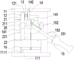
Fig. 1 is a schematic structural view of the lateral core-pulling injection mold of the present invention.
Detailed Description
The invention will be further elucidated and described with reference to the following embodiments and drawings in which:
referring to fig. 1, the injection mold for lateral core pulling includes an upper mold base 11, an upper mold 21, a lower mold 22, and an ejector plate 16 located below, and is characterized by further including a rack column 12, the rack column penetrates through the lower mold 22 and the upper mold 21, a tooth-shaped protrusion 121 is disposed on the rack column 12, the tooth-shaped protrusion 121 is engaged with a gear 13 disposed on the upper mold 21, the gear 13 is fixedly connected with the upper mold 21, the other side of the gear 13 opposite to the rack column 121 is engaged with a rack 14, and the rack 14 is movably connected with the upper mold base 11 and penetrates through the upper mold 21. So that the plastic part 20 is convenient to demould.
An upper mold core 211 and a lower mold core 221 which are matched with each other are arranged between the upper mold 21 and the lower mold 22.
The plastic part 20 is arranged between the upper mold core 211 and the lower mold core 221 during injection molding, the contact surface of the rack 14 and the plastic part 20 is provided with the protrusion 141, the contact area of the rack 14 and the plastic part 20 is increased, further, the friction force is increased, the rack 14 drives the plastic part conveniently during mold opening, the volume of the rack 14 extending into the plastic part 20 is 10% of the volume of the plastic part 20, and the friction force is increased to the maximum extent under the condition that the plastic part is not influenced.
An oil cylinder seat 153 fixedly connected with the outer side of the lower die 22 is arranged on the outer side of the lower die, an oil cylinder 15 fixedly connected with the outer side of the oil cylinder seat 153 is arranged in the oil cylinder 15, an oil cylinder shaft 151 penetrating through the oil cylinder seat 153 is arranged in the oil cylinder 15, a sliding block 152 is arranged at one end, far away from the oil cylinder seat 153, of the oil cylinder shaft 151, the sliding block 152 is fixedly connected with the oil cylinder shaft 151, and the sliding block 152 abuts against the plastic. When the mold is opened, the cylinder shaft 151 moves along the cylinder 15 to drive the slider 152 to be drawn out, so that the plastic part 20 is conveniently ejected through the ejector pin 161.
The anti-collision block 142 is arranged between the upper die holder 11 and the rack 14, so that when a fault occurs, the rack 14 moves too long to the upper die holder 11, and collides with the upper die holder 11, and the service life of the rack 14 is not affected.
The ejector plate 16 is provided with an ejector pin 161, and the ejector pin 161 penetrates through the lower die 22 and the lower die core 221 to contact with the plastic part 20. The ejector pins 161 eject the plastic part 20 under the movement of the ejector plate 16, so as to facilitate the separation of the plastic part 20 from the lower mold core 221.
A lower die holder 111 is arranged below the ejector plate 16, and a limit block 1111 is arranged on one side of the lower die holder 111 close to the ejector plate 16. When the mould resets, prevent that thimble board 161 from colliding with die holder 111, guarantee mould life.
The utility model provides an injection mold of side direction loose core, after the injection molding of molten plastic, a part moulds 20 parcel rack 14, when the die sinking, lower mould 22 is kept away from last mould 21, rack column 12 on locating lower mould 22 moves along with lower mould 22, dentate protuberance 121 on rack column 12 keeps away from last mould 21, gear 13 that meshes with dentate protuberance 121 at this moment rotates, drive rack 14 and move to upper die base 11 direction motion, because mould 20 parcel rack 14 and produce the frictional force, rack 14 drives moulds 20 and moves to last mould 21, meanwhile thimble 161 on thimble board 16 is ejecting, mould 20 under the combined action of both breaks away from lower mould benevolence 221 smoothly, rack 14 continues to move to last mould 21, because last mould benevolence 211 blocks mould 20 and removes, the frictional force that mould 20 parcel rack 14 produced is less than the power that upper mould benevolence 211 blocks mould 20, mould 20 breaks away from rack 14, the plastic part 20 falls by itself. The plastic part 20 is convenient to demould, workers can pick up the plastic part 20 conveniently, and the number of the ejector pins 161 can be reduced, so that the aim of saving cost is fulfilled.
It should be finally noted that the above embodiments are only intended to illustrate the technical solutions of the present invention, and not to limit the scope of the present invention, and although the present invention has been described in detail with reference to the preferred embodiments, it should be understood by those skilled in the art that the technical solutions of the present invention can be modified or replaced with equivalents without departing from the spirit and scope of the technical solutions of the present invention.
Claims (7)
1. The utility model provides an injection mold of side direction core pulling, includes the upper die base that stacks in proper order, goes up mould, lower mould, still includes the thimble board that is located the below, its characterized in that still includes the rack post, the rack post runs through the lower mould go up the mould, be equipped with the cusp on the rack post and protruding, the gear of last mould is located in the meshing of cusp, gear and last mould fixed connection, the gear for rack post opposite side and rack toothing, the rack with upper die base swing joint runs through go up the mould.
2. The lateral core pulling injection mold according to claim 1, wherein an upper mold core and a lower mold core which are matched with each other are arranged between the upper mold and the lower mold.
3. The injection mold with the lateral loose core according to claim 2, wherein a plastic part during injection molding is arranged between the upper mold core and the lower mold core, a protrusion is arranged on a contact surface of the rack and the plastic part, and the volume of the rack extending into the plastic part is 10% of the volume of the plastic part.
4. The injection mold of claim 3, wherein an oil cylinder seat is fixedly connected to the outer side of the lower mold, an oil cylinder is fixedly connected to the outer side of the oil cylinder seat, an oil cylinder shaft penetrating through the oil cylinder seat is arranged in the oil cylinder, a sliding block is arranged at one end, away from the oil cylinder seat, of the oil cylinder shaft, the sliding block is fixedly connected with the oil cylinder shaft, and the sliding block abuts against the plastic part.
5. The lateral core pulling injection mold according to claim 1, wherein an anti-collision block is arranged between the upper mold base and the rack.
6. The lateral core pulling injection mold according to claim 1, wherein the ejector plate is provided with an ejector pin, and the ejector pin penetrates through the lower mold and the lower mold core and contacts with the plastic part.
7. The injection mold of claim 6, wherein a lower die holder is arranged below the ejector plate, and a limiting block is arranged on one side of the lower die holder, which is close to the ejector plate.
Priority Applications (1)
| Application Number | Priority Date | Filing Date | Title |
|---|---|---|---|
| CN201920794039.3U CN210758981U (en) | 2019-05-30 | 2019-05-30 | Injection mold with lateral core pulling function |
Applications Claiming Priority (1)
| Application Number | Priority Date | Filing Date | Title |
|---|---|---|---|
| CN201920794039.3U CN210758981U (en) | 2019-05-30 | 2019-05-30 | Injection mold with lateral core pulling function |
Publications (1)
| Publication Number | Publication Date |
|---|---|
| CN210758981U true CN210758981U (en) | 2020-06-16 |
Family
ID=71051045
Family Applications (1)
| Application Number | Title | Priority Date | Filing Date |
|---|---|---|---|
| CN201920794039.3U Active CN210758981U (en) | 2019-05-30 | 2019-05-30 | Injection mold with lateral core pulling function |
Country Status (1)
| Country | Link |
|---|---|
| CN (1) | CN210758981U (en) |
Cited By (1)
| Publication number | Priority date | Publication date | Assignee | Title |
|---|---|---|---|---|
| CN111957832A (en) * | 2020-08-20 | 2020-11-20 | 张运杰 | Cutter seat for mold and mold |
-
2019
- 2019-05-30 CN CN201920794039.3U patent/CN210758981U/en active Active
Cited By (1)
| Publication number | Priority date | Publication date | Assignee | Title |
|---|---|---|---|---|
| CN111957832A (en) * | 2020-08-20 | 2020-11-20 | 张运杰 | Cutter seat for mold and mold |
Similar Documents
| Publication | Publication Date | Title |
|---|---|---|
| CN2873467Y (en) | Slide block adding false center auxiliary lift-out structure in mould | |
| CN210758981U (en) | Injection mold with lateral core pulling function | |
| CN211054322U (en) | Injection mold of internal thread product | |
| CN216992904U (en) | Fixed die inclined ejection mechanism of injection mold | |
| CN216001294U (en) | Injection molding mold for automobile door handle | |
| CN215039836U (en) | Forming die for producing precise injection molding parts | |
| CN201784103U (en) | Secondary core-pulling mechanism for inclined guide pillar of base mould of automobile headlamp | |
| CN212795716U (en) | Oblique ejection die | |
| CN101979811B (en) | Component and die structure and forming method for producing same | |
| CN101966741B (en) | Opening and closing device of two-layer injection mold of storage battery plastic cover | |
| CN218399274U (en) | Bidirectional ejection die | |
| CN219686439U (en) | Demoulding structure of mould | |
| CN217258134U (en) | Mould benevolence assembly of shaping major arc product | |
| CN217729553U (en) | Mould contracts and is extremely well with push pedal ejection mechanism | |
| CN219855571U (en) | Built-in inclined ejection device of inclined drawing sliding block of plastic mold oil cylinder | |
| CN216465988U (en) | Traceless demolding mold for transparent product | |
| CN215703796U (en) | Forming die of upper cover | |
| CN216968543U (en) | Prevent oblique bullet top die structure of product adhesion | |
| CN215921186U (en) | Injection mold for product with inner buckle on upper mold | |
| CN214872395U (en) | Supplementary demolding trip position device of slider | |
| CN210257108U (en) | Anti-sticking oblique-ejection mechanism of injection mold | |
| CN215849426U (en) | Compound side direction injection mould of loosing core | |
| CN211993958U (en) | Mold ejection structure | |
| CN220562096U (en) | Ejecting core-pulling device and mould | |
| CN219028340U (en) | Mould with inclined hole core-pulling mechanism |
Legal Events
| Date | Code | Title | Description |
|---|---|---|---|
| GR01 | Patent grant | ||
| GR01 | Patent grant |