CN210753756U - Rice processing buffer - Google Patents
Rice processing buffer Download PDFInfo
- Publication number
- CN210753756U CN210753756U CN201921635863.0U CN201921635863U CN210753756U CN 210753756 U CN210753756 U CN 210753756U CN 201921635863 U CN201921635863 U CN 201921635863U CN 210753756 U CN210753756 U CN 210753756U
- Authority
- CN
- China
- Prior art keywords
- sliding
- rod
- buffer box
- buffer
- cross rod
- Prior art date
- Legal status (The legal status is an assumption and is not a legal conclusion. Google has not performed a legal analysis and makes no representation as to the accuracy of the status listed.)
- Active
Links
Images


Landscapes
- Combined Means For Separation Of Solids (AREA)
Abstract
The utility model discloses a rice processing buffer, concretely relates to rice processing field, including the baffle-box, the baffle-box top is equipped with the inlet pipe, the inside first vibration mechanism that is equipped with of baffle-box, the inside second vibration mechanism that is equipped with of baffle-box, first vibration mechanism includes the motor, the motor sets up in inlet pipe one side, motor and baffle-box fixed connection, motor output shaft one end fixedly connected with rotary rod, rotary rod one side is equipped with the head rod, the head rod is articulated with the rotary rod, head rod one side is equipped with first horizontal pole. The utility model discloses a motor output shaft drives the rotary rod and rotates to drive the head rod and reciprocate, thereby drive first horizontal pole and reciprocate, thereby drive first slider and reciprocate along first spout, thereby drive first screen cloth vibration from top to bottom, thereby sieve the rice that falls on first screen cloth.
Description
Technical Field
The utility model relates to a rice processing field, more specifically say, the utility model relates to a rice processing buffer.
Background
In the rice processing technology, the layout mode of each device is mostly adopted from top to bottom, and in the processing process, rice generates larger impact force with a machine due to too fast falling speed, so that rice grains are broken, and the rice yield of finished products is reduced.
The existing rice processing buffer device can effectively absorb kinetic energy generated in the rice falling process through the inclined baffle, and the speed of the rice falling process is reduced, so that the probability of breakage of the rice due to too fast impact generation is reduced, and the rice yield of the product is improved.
However, it cannot be used for screening broken rice produced in the previous step.
SUMMERY OF THE UTILITY MODEL
In order to overcome the above-mentioned defect of prior art, the embodiment of the utility model provides a rice processing buffer, it rotates to drive the rotary rod through motor output shaft, thereby it reciprocates to drive the head rod, thereby it reciprocates to drive first horizontal pole, thereby it reciprocates to drive the montant, thereby it reciprocates to drive the second horizontal pole, thereby it reciprocates along first spout to drive first slider, thereby it reciprocates to drive first connecting plate, thereby it vibrates from top to bottom to drive first screen cloth, thereby it sieves the rice that falls on first screen cloth to vibrate from top to bottom to first screen cloth, the broken rice that produces the preceding process sieves out, in order to solve the problem that proposes among the above-mentioned background art.
In order to achieve the above object, the utility model provides a following technical scheme: a rice processing buffering device comprises a buffering box, wherein a feeding pipe is arranged at the top of the buffering box, a first vibrating mechanism is arranged inside the buffering box, and a second vibrating mechanism is arranged inside the buffering box;
the first vibration mechanism comprises a motor, the motor is arranged on one side of the feeding pipe, the motor is fixedly connected with the buffer tank, one end of an output shaft of the motor is fixedly connected with a rotating rod, one side of the rotating rod is provided with a first connecting rod, the first connecting rod is hinged with the rotating rod, one side of the first connecting rod is provided with a first cross rod, the first cross rod is hinged with the first connecting rod, two vertical rods are arranged on two sides of the first cross rod and are respectively fixedly connected with two ends of the first cross rod, a second cross rod is arranged between the two vertical rods, the number of the second cross rods is two, the second cross rod is arranged at the bottom of the first cross rod, one side of the second cross rod is provided with a plurality of first sliding blocks, the second cross rod is fixedly connected with the first sliding blocks, one side of the buffer tank is provided with a plurality of first sliding grooves, and, the first sliding block is arranged inside the first sliding groove, the first sliding block extends into the buffer box, a first connecting plate is arranged at one end of the first sliding block, the first connecting plate is fixedly connected with the first sliding block, the first connecting plate is arranged inside the buffer box, a first screen is arranged on one side of the first connecting plate, a first sliding plate is arranged on one side of the first screen, the first sliding plate is hinged with the first screen, the other end of the first sliding plate is hinged with the buffer box, a second connecting rod is arranged on each of two vertical rods, and the second connecting rods are hinged with the vertical rods;
the second vibration mechanism comprises a third cross bar which is arranged between the two second connecting rods, two ends of the third cross rod are respectively hinged with the two second connecting rods, the third cross rod is arranged at the other side of the buffer tank, a plurality of second sliding blocks are arranged on one side of the third cross bar, the third cross bar is fixedly connected with the second sliding blocks, a plurality of second sliding grooves are arranged on one side of the buffer box, the second sliding blocks are matched with the second sliding grooves, the second sliding block is arranged in the second sliding groove, the second sliding block extends into the buffer box, one end of the second sliding block is provided with a second connecting plate, the second connecting plate is fixedly connected with the second sliding block, the second connecting plate is arranged in the buffer box, a second screen is arranged on one side of the second connecting plate, a second sliding plate is arranged on one side of the second screen, the second sliding plate is hinged to the second screen, and the other end of the second sliding plate is hinged to the buffer box.
In a preferred embodiment, the bottom of the buffer box is provided with an outlet hopper, and the outlet hopper is fixedly connected with the buffer box.
In a preferred embodiment, a first collecting pipe is arranged on one side of the buffer box, penetrates through the buffer box and extends to one side of the first sliding plate.
In a preferred embodiment, the buffer tank is provided with second collecting pipes at two sides, and the second collecting pipes penetrate through the buffer tank and extend to one side of the second sliding plate.
In a preferred embodiment, two second connecting rods are symmetrically distributed at the front side and the rear side of the buffer box, and the second connecting rods are hinged with the buffer box.
In a preferred embodiment, the first slider and the second slider are provided in a cross-shaped sectional shape.
In a preferred embodiment, the first screen, the first sliding plate, the second screen and the second sliding plate are all arranged in an inclined shape.
The utility model discloses a technological effect and advantage:
1. the rotating rod is driven to rotate through the output shaft of the motor, so that the first connecting rod is driven to move up and down, the first transverse rod is driven to move up and down, the vertical rod is driven to move up and down, the second transverse rod is driven to move up and down, the first sliding block is driven to move up and down along the first sliding groove, the first connecting plate is driven to move up and down, the first screen is driven to vibrate up and down, the first screen vibrates up and down so as to screen rice falling on the first screen, broken rice generated in the previous process is screened out, compared with the prior art, broken rice generated in the previous process can be screened, and the screening effect is good;
2. through setting up first slider cross sectional shape into the cross, restriction first slider can only follow first spout and remove to restriction first connecting plate can only reciprocate, thereby makes the upper and lower vibration that first screen cloth can be steady, can not the skew rock, compares with prior art, and the vibration effect is better, and is more reasonable in structure, is difficult to take place the skew.
Drawings
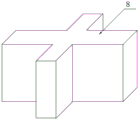
Fig. 1 is a schematic view of the overall structure of the present invention.
Fig. 2 is a front view of the present invention.
Fig. 3 is a side view of the present invention.
Fig. 4 is a schematic perspective view of the first slider of the present invention.
Fig. 5 is an enlarged view of the structure of the portion a of fig. 1 according to the present invention.
The reference signs are: 1 baffle-box, 2 motors, 3 rotary rods, 4 head rods, 5 first horizontal rods, 6 vertical rods, 7 second horizontal rods, 8 first sliders, 9 first chutes, 10 first connecting plates, 11 first screens, 12 first sliding plates, 13 second connecting rods, 14 third horizontal rods, 15 second sliders, 16 second chutes, 17 second connecting plates, 18 second screens, 19 second sliding plates, 20 discharge hoppers, 21 first collecting pipes and 22 second collecting pipes.
Detailed Description
The technical solutions in the embodiments of the present invention will be described clearly and completely with reference to the accompanying drawings in the embodiments of the present invention, and it is obvious that the described embodiments are only some embodiments of the present invention, not all embodiments. Based on the embodiments in the present invention, all other embodiments obtained by a person skilled in the art without creative work belong to the protection scope of the present invention.
The utility model provides a rice processing buffer device as shown in figures 1-5, which comprises a buffer box 1, wherein a feeding pipe is arranged at the top of the buffer box 1, a first vibrating mechanism is arranged inside the buffer box 1, and a second vibrating mechanism is arranged inside the buffer box 1;
the first vibration mechanism comprises a motor 2, the motor 2 is arranged on one side of the inlet pipe, the motor 2 is fixedly connected with a buffer tank 1, one end of an output shaft of the motor 2 is fixedly connected with a rotary rod 3, one side of the rotary rod 3 is provided with a first connecting rod 4, the first connecting rod 4 is hinged with the rotary rod 3, one side of the first connecting rod 4 is provided with a first cross rod 5, the first cross rod 5 is hinged with the first connecting rod 4, two vertical rods 6 are respectively arranged on two sides of the first cross rod 5, the two vertical rods 6 are respectively and fixedly connected with two ends of the first cross rod 5, a second cross rod 7 is arranged between the two vertical rods 6, the number of the second cross rods 7 is two, the second cross rods 7 are arranged at the bottom of the first cross rod 5, one side of the second cross rod 7 is provided with a plurality of first slide blocks 8, the second cross rod 7 is fixedly connected with the first slide blocks 8, one side of the, the first sliding block 8 is matched with the first sliding groove 9, the first sliding block 8 is arranged inside the first sliding groove 9, the first sliding block 8 extends into the buffer box 1, a first connecting plate 10 is arranged at one end of the first sliding block 8, the first connecting plate 10 is fixedly connected with the first sliding block 8, the first connecting plate 10 is arranged inside the buffer box 1, a first screen 11 is arranged on one side of the first connecting plate 10, a first sliding plate 12 is arranged on one side of the first screen 11, the first sliding plate 12 is hinged with the first screen 11, the other end of the first sliding plate 12 is hinged with the buffer box 1, a second connecting rod 13 is arranged on one side of each of two vertical rods 6, and the second connecting rods 13 are hinged with the vertical rods 6;
the second vibration mechanism comprises a third cross rod 14, the third cross rod 14 is arranged between two second connecting rods 13, two ends of the third cross rod 14 are respectively hinged with the two second connecting rods 13, the third cross rod 14 is arranged on the other side of the buffer box 1, one side of the third cross rod 14 is provided with a plurality of second sliding blocks 15, the third cross rod 14 is fixedly connected with the second sliding blocks 15, one side of the buffer box 1 is provided with a plurality of second sliding grooves 16, the second sliding blocks 15 are matched with the second sliding grooves 16, the second sliding blocks 15 are arranged inside the second sliding grooves 16, the second sliding blocks 15 extend into the buffer box 1, one end of each second sliding block 15 is provided with a second connecting plate 17, the second connecting plates 17 are fixedly connected with the second sliding blocks 15, the second connecting plates 17 are arranged inside the buffer box 1, one side of each second connecting plate 17 is provided with a second screen 18, one side of each second screen 18 is provided with a second sliding plate 19, the second sliding plate 19 is hinged with the second screen 18, and the other end of the second sliding plate 19 is hinged with the buffer tank 1;
a discharge hopper 20 is arranged at the bottom of the buffer box 1, and the discharge hopper 20 is fixedly connected with the buffer box 1;
a first collecting pipe 21 is arranged on one side of the buffer box 1, and the first collecting pipe 21 penetrates through the buffer box 1 and extends to one side of the first sliding plate 12;
a second collecting pipe 22 is arranged on the two sides of the buffer tank 1, and the second collecting pipe 22 penetrates through the buffer tank 1 and extends to one side of the second sliding plate 19;
the two second connecting rods 13 are symmetrically distributed on the front side and the rear side of the buffer box 1, and the second connecting rods 13 are hinged with the buffer box 1;
the first screen 11, the first sliding plate 12, the second screen 18 and the second sliding plate 19 are all arranged in an inclined shape;
the implementation mode is specifically as follows: when the utility model is used, rice enters the buffer box 1 through the inlet pipe and then falls on the first screen mesh 11, the motor 2 is started, the output shaft of the motor 2 drives the rotating rod 3 to rotate, thereby driving the first connecting rod 4 to move up and down, thereby driving the first cross rod 5 to move up and down, thereby driving the vertical rod 6 to move up and down, thereby driving the second cross rod 7 to move up and down, thereby driving the first slider 8 to move up and down along the first chute 9, thereby driving the first connecting plate 10 to move up and down, thereby driving the first screen mesh 11 to vibrate up and down, thereby screening the rice falling on the first screen mesh 11, screening out broken rice generated in the previous process, falling on the first sliding plate 12 through the first screen mesh 11, then sliding down from the first sliding plate 12, passing through the first discharge port, falling into the first collecting pipe 21, thereby vibrating the first drying net to make the complete rice slide down from the first drying net, fall into on second screen cloth 18, thereby montant 6 reciprocates simultaneously and drives second connecting rod 13 one end and reciprocates, thereby it reciprocates to drive the second connecting rod 13 other end, thereby it reciprocates to drive third horizontal pole 14, thereby it reciprocates to drive second slider 15, thereby it reciprocates to drive second connecting plate 17, thereby it vibrates from top to bottom to drive second screen cloth 18, thereby carry out secondary screening to the rice that falls on second screen cloth 18, then fall into out hopper 20, this embodiment has specifically solved the problem that can not carry out the screening to the broken rice that the previous process produced among the prior art.
The utility model provides a rice processing buffer device as shown in figure 1, figure 4 and figure 5, the cross section shapes of the first slide block 8 and the second slide block 15 are arranged into a cross shape;
the implementation mode is specifically as follows: set up to the cross through 8 cross sectional shapes with first slider, restrict first slider 8 and can only remove along first spout 9 to restriction first connecting plate 10 can only reciprocate, thereby make the upper and lower vibration that first screen cloth 11 can be steady, can not the skew rock, can take place the problem of skew when this embodiment has specifically solved machine screen cloth vibration among the prior art.
The utility model discloses the theory of operation:
referring to the attached drawings 1-5 of the specification, an output shaft of a motor 2 drives a rotating rod 3 to rotate, thereby driving a first connecting rod 4 to move up and down, thereby driving a first cross rod 5 to move up and down, thereby driving a vertical rod 6 to move up and down, thereby driving a second cross rod 7 to move up and down, thereby driving a first sliding block 8 to move up and down along a first sliding groove 9, thereby driving a first connecting plate 10 to move up and down, thereby driving a first screen mesh 11 to vibrate up and down, thereby screening rice falling on the first screen mesh 11, thereby vibrating the first screen mesh to make complete rice slide down from the first screen mesh, thereby falling on a second screen mesh 18, and simultaneously, the vertical rod 6 moves up and down to drive one end of a second connecting rod 13 to move up and down, thereby driving the other end of the second connecting rod 13 to move up and down, thereby driving a third, thereby driving the second connecting plate 17 to move up and down, thereby driving the second screen 18 to vibrate up and down, thereby performing secondary screening on the rice falling on the second screen 18 and then falling into the discharging hopper 20;
referring to the attached drawings 1, 4 and 5 of the specification, the first sliding block 8 is limited to move only along the first sliding groove 9 by setting the cross-sectional shape of the first sliding block 8 into a cross shape, so that the first connecting plate 10 is limited to move only up and down, and the first screen 11 can stably vibrate up and down without deviation and shaking.
The points to be finally explained are: first, in the description of the present application, it should be noted that, unless otherwise specified and limited, the terms "mounted," "connected," and "connected" should be understood broadly, and may be a mechanical connection or an electrical connection, or a communication between two elements, and may be a direct connection, and "upper," "lower," "left," and "right" are only used to indicate a relative positional relationship, and when the absolute position of the object to be described is changed, the relative positional relationship may be changed;
secondly, the method comprises the following steps: in the drawings of the disclosed embodiments of the present invention, only the structures related to the disclosed embodiments are referred to, and other structures can refer to the common design, and under the condition of no conflict, the same embodiment and different embodiments of the present invention can be combined with each other;
and finally: the above description is only for the preferred embodiment of the present invention and should not be taken as limiting the invention, and any modifications, equivalent replacements, improvements, etc. made within the spirit and principle of the present invention should be included in the protection scope of the present invention.
Claims (7)
1. The utility model provides a rice processing buffer, includes surge-box (1), its characterized in that: the top of the buffer box (1) is provided with a feeding pipe, a first vibrating mechanism is arranged inside the buffer box (1), and a second vibrating mechanism is arranged inside the buffer box (1);
the first vibration mechanism comprises a motor (2), the motor (2) is arranged on one side of the inlet pipe, the motor (2) is fixedly connected with the buffer tank (1), one end of an output shaft of the motor (2) is fixedly connected with a rotary rod (3), one side of the rotary rod (3) is provided with a first connecting rod (4), the first connecting rod (4) is hinged with the rotary rod (3), one side of the first connecting rod (4) is provided with a first cross rod (5), the first cross rod (5) is hinged with the first connecting rod (4), two vertical rods (6) are arranged on two sides of the first cross rod (5), the two vertical rods (6) are respectively fixedly connected with two ends of the first cross rod (5), a second cross rod (7) is arranged between the two vertical rods (6), the number of the second cross rods (7) is two, and the second cross rod (7) is arranged at the bottom of the first cross rod (5), a plurality of first sliding blocks (8) are arranged on one side of the second cross rod (7), the second cross rod (7) is fixedly connected with the first sliding blocks (8), a plurality of first sliding grooves (9) are arranged on one side of the buffer box (1), the first sliding blocks (8) are matched with the first sliding grooves (9), the first sliding blocks (8) are arranged inside the first sliding grooves (9), the first sliding blocks (8) extend into the buffer box (1), a first connecting plate (10) is arranged at one end of each first sliding block (8), the first connecting plate (10) is fixedly connected with the first sliding blocks (8), the first connecting plate (10) is arranged inside the buffer box (1), a first screen (11) is arranged on one side of the first connecting plate (10), a first sliding plate (12) is arranged on one side of the first screen (11), and the first sliding plate (12) is hinged with the first screen (11), the other end of the first sliding plate (12) is hinged with the buffer box (1), a second connecting rod (13) is arranged on one side of each of the two vertical rods (6), and the second connecting rods (13) are hinged with the vertical rods (6);
the second vibration mechanism comprises a third cross rod (14), the third cross rod (14) is arranged between two second connecting rods (13), two ends of the third cross rod (14) are respectively hinged with the two second connecting rods (13), the third cross rod (14) is arranged on the other side of the buffer box (1), one side of the third cross rod (14) is provided with a plurality of second sliding blocks (15), the third cross rod (14) is fixedly connected with the second sliding blocks (15), one side of the buffer box (1) is provided with a plurality of second sliding grooves (16), the second sliding blocks (15) are matched with the second sliding grooves (16), the second sliding blocks (15) are arranged inside the second sliding grooves (16), the second sliding blocks (15) extend into the buffer box (1), one end of each second sliding block (15) is provided with a second connecting plate (17), and the second connecting plates (17) are fixedly connected with the second sliding blocks (15), the second connecting plate (17) is arranged inside the buffer box (1), a second screen (18) is arranged on one side of the second connecting plate (17), a second sliding plate (19) is arranged on one side of the second screen (18), the second sliding plate (19) is hinged to the second screen (18), and the other end of the second sliding plate (19) is hinged to the buffer box (1).
2. The rice processing buffer device of claim 1, wherein: the buffer box is characterized in that a discharge hopper (20) is arranged at the bottom of the buffer box (1), and the discharge hopper (20) is fixedly connected with the buffer box (1).
3. The rice processing buffer device of claim 1, wherein: buffer bin (1) one side is equipped with first collecting pipe (21), first collecting pipe (21) run through buffer bin (1) and extend to first slide (12) one side.
4. The rice processing buffer device of claim 1, wherein: and second collecting pipes (22) are arranged on two sides of the buffer box (1), and the second collecting pipes (22) penetrate through the buffer box (1) and extend to one side of the second sliding plate (19).
5. The rice processing buffer device of claim 1, wherein: the two second connecting rods (13) are symmetrically distributed on the front side and the rear side of the buffer box (1), and the second connecting rods (13) are hinged to the buffer box (1).
6. The rice processing buffer device of claim 1, wherein: the cross section shapes of the first sliding block (8) and the second sliding block (15) are set to be cross-shaped.
7. The rice processing buffer device of claim 1, wherein: the first screen (11), the first sliding plate (12), the second screen (18) and the second sliding plate (19) are all arranged in an inclined shape.
Priority Applications (1)
| Application Number | Priority Date | Filing Date | Title |
|---|---|---|---|
| CN201921635863.0U CN210753756U (en) | 2019-09-29 | 2019-09-29 | Rice processing buffer |
Applications Claiming Priority (1)
| Application Number | Priority Date | Filing Date | Title |
|---|---|---|---|
| CN201921635863.0U CN210753756U (en) | 2019-09-29 | 2019-09-29 | Rice processing buffer |
Publications (1)
| Publication Number | Publication Date |
|---|---|
| CN210753756U true CN210753756U (en) | 2020-06-16 |
Family
ID=71034165
Family Applications (1)
| Application Number | Title | Priority Date | Filing Date |
|---|---|---|---|
| CN201921635863.0U Active CN210753756U (en) | 2019-09-29 | 2019-09-29 | Rice processing buffer |
Country Status (1)
| Country | Link |
|---|---|
| CN (1) | CN210753756U (en) |
Cited By (2)
| Publication number | Priority date | Publication date | Assignee | Title |
|---|---|---|---|---|
| CN112221552A (en) * | 2020-09-07 | 2021-01-15 | 衡南世源农业发展有限公司 | Selenium-rich rice processing equipment |
| CN113102243A (en) * | 2021-03-04 | 2021-07-13 | 何金领 | Vibration screening device for tea production |
-
2019
- 2019-09-29 CN CN201921635863.0U patent/CN210753756U/en active Active
Cited By (2)
| Publication number | Priority date | Publication date | Assignee | Title |
|---|---|---|---|---|
| CN112221552A (en) * | 2020-09-07 | 2021-01-15 | 衡南世源农业发展有限公司 | Selenium-rich rice processing equipment |
| CN113102243A (en) * | 2021-03-04 | 2021-07-13 | 何金领 | Vibration screening device for tea production |
Similar Documents
| Publication | Publication Date | Title |
|---|---|---|
| CN210753756U (en) | Rice processing buffer | |
| CN206229509U (en) | A kind of screening baiting structure of plastic breaker | |
| CN207770313U (en) | A kind of vibrating screen that can improve screening precision | |
| CN206262865U (en) | A kind of corn processing multi-stage oscillating screen | |
| CN108212748A (en) | A kind of sandstone separator of connecting rod cam type transmission | |
| CN109701703A (en) | Construction waste crushing and screening device and its screening technique | |
| CN109731773A (en) | A kind of chemical industry powder classification vibration screening machine | |
| CN109201451A (en) | A kind of rice automation screening processing and fabricating equipment | |
| CN209317818U (en) | A kind of efficient coal picker | |
| CN214766808U (en) | Improved generation multistage linear vibration sieve | |
| CN210253093U (en) | Rice seed edulcoration sieving mechanism | |
| CN107694719B (en) | Multi-stage screening and crushing linkage machine and screening production line thereof | |
| CN218502613U (en) | Quick sieving mechanism of root of kudzu vine piece | |
| CN208527226U (en) | A kind of high efficiency shake bat formula sand sieving machine | |
| CN106362831B (en) | A kind of hammer mill crushed for alcohol raw material | |
| CN207071511U (en) | A kind of vibratory sieve | |
| CN207413804U (en) | A kind of Multifunctional tea screening installation | |
| CN215918110U (en) | Drum sand screening machine for building engineering construction | |
| CN213468619U (en) | Pellet granule sieving mechanism | |
| CN212702959U (en) | A classifying screen feed arrangement that shakes for machine-made white sand production | |
| CN205926301U (en) | Production refractory material's sieving mechanism | |
| CN212597103U (en) | Attapulgite clay vibration screening plant | |
| CN210906949U (en) | Multifunctional material classifier | |
| CN206661290U (en) | A kind of jaw crusher | |
| CN207358070U (en) | Sand mixer sand sieving machine |
Legal Events
| Date | Code | Title | Description |
|---|---|---|---|
| GR01 | Patent grant | ||
| GR01 | Patent grant |