CN210740717U - Preheating device for facilitating air flow in aerobic fermentation - Google Patents
Preheating device for facilitating air flow in aerobic fermentation Download PDFInfo
- Publication number
- CN210740717U CN210740717U CN201921172561.4U CN201921172561U CN210740717U CN 210740717 U CN210740717 U CN 210740717U CN 201921172561 U CN201921172561 U CN 201921172561U CN 210740717 U CN210740717 U CN 210740717U
- Authority
- CN
- China
- Prior art keywords
- reaction box
- heating cabinet
- preheating device
- fixed mounting
- air
- Prior art date
- Legal status (The legal status is an assumption and is not a legal conclusion. Google has not performed a legal analysis and makes no representation as to the accuracy of the status listed.)
- Active
Links
Images


Landscapes
- Apparatus Associated With Microorganisms And Enzymes (AREA)
Abstract
The utility model discloses an aerobic fermentation does benefit to preheating device that air flows relates to preheating device technical field, and its technical scheme's main points are: including heating cabinet and reaction box, the intercommunication has the connecting tube between heating cabinet and the reaction box, the left side fixed mounting of heating cabinet has two extraction fans, two exhaust duct have been seted up on the right side of reaction box, exhaust duct right side fixed mounting has the air discharge fan, exhaust duct's inside fixed mounting has the filter screen, the air can heat and enter into the reaction box inside heating cabinet after getting into, the air can preheat the inside material of heating cabinet after getting into, the in-process gas experience that preheats circulates inside the reaction box, the rotation of the in-process air discharge fan at the circulation can discharge the inside hot gas of reaction box, the circulation of the inside air of assurance device, and extraction fan and air discharge fan all are provided with two, can guarantee that the air can be quick follow with trading and the circulation.
Description
Technical Field
The utility model relates to a preheating device's technical field, in particular to preheating device that good oxygen fermentation does benefit to air flow.
Background
The preheater is a heating surface which preheats air before entering the boiler to a certain temperature by using flue gas in a flue at the tail part of the boiler through internal radiating fins. The heat exchange performance of the boiler is improved, and the energy consumption is reduced.
However, the existing preheating device can not discharge the air in a circulating manner in the preheating process, which results in poor air circulation effect.
SUMMERY OF THE UTILITY MODEL
To the deficiency that prior art exists, the utility model aims to: the problem of preheating device in the aspect of circulation of air is improved.
Above-mentioned technical purpose is realized through following technical scheme, a preheating device that aerobic fermentation does benefit to air flow, including heating cabinet and reaction box, the intercommunication has the connecting tube between heating cabinet and the reaction box, the top welding of reaction box has the motor, the left side intercommunication of reaction box has the conveyer pipe, the left side fixed mounting of heating cabinet has two extraction fans, two exhaust duct have been seted up on the right side of reaction box, exhaust duct right side fixed mounting has the air discharge fan, exhaust duct's inside fixed mounting has the filter screen.
Through the technical scheme: can inhale the heating cabinet inside with the outside gas of device through the rotation of aspirating fan, the air can heat and enter into the reaction box inside heating cabinet after getting into, the air can preheat the inside material of heating cabinet after getting into, can circulate inside the reaction box at the in-process gas-cooker of preheating, the rotation of the in-process air discharge fan of circulation can be discharged the inside heat gas of reaction box, the circulation of the inside air of assurance device, and aspirating fan and air discharge fan all are provided with two, can guarantee that the air can be quick follow-up with trading and the circulation.
Preferably, the inside fixed mounting of heating cabinet has the heating pipe, the heating pipe is the staggered distribution, the inside below left side fixed mounting of heating cabinet has the temperature-sensing appearance, the right side middle part swing joint of heating cabinet has electric valve.
Through the technical scheme: the heating pipe can heat the air that gets into the heating cabinet inside, and the heating pipe adopts crisscross distribution can be quick to the air heat, and the in-process temperature-sensing appearance that heats can respond to the inside temperature of heating chamber to turn into signal transmission to panel department with the temperature of response.
Preferably, the inside top middle part swing joint of reaction box has the pivot, the bottom welding of pivot has the dead lever, the both sides welding of dead lever has a plurality of stirring rakes.
Through the technical scheme: inside the commodity circulation gets into the reaction box, the rotation of pivot can drive dead lever and stirring rake and rotate, and the stirring rake can stir the commodity circulation that gets into at the pivoted in-process, makes the material disperse, and the heat air that the packing got into can be even preheats the commodity circulation.
Preferably, a discharge hole is formed in the middle of the lower portion of the inside of the reaction box, and an electric valve is movably connected to the left side of the lower portion of the inside of the reaction box.
Through the technical scheme: can seal and open the discharge gate through electric valve, can discharge the commodity circulation through the discharge gate after preheating and accomplishing.
Preferably, the rear end of the heating box is provided with a rear cover, a heat dissipation opening is fixedly arranged above the middle part of the rear end of the rear cover, and the outside of the heat dissipation opening is movably connected with a movable door.
Through the technical scheme: can use the heat discharge with the inside heat of heating cabinet after accomplishing at the heating cabinet through the thermovent, and promote the dodge gate and can seal the thermovent after the thermovent uses the completion.
Preferably, the rear end of the rear cover is provided with four screw holes.
Through the technical scheme: can fix the back lid behind the heating cabinet through four screws, make things convenient for the staff to dismantle.
Preferably, a battery compartment is fixedly mounted below the middle part of the rear end of the rear cover, and a storage battery is movably connected inside the battery compartment.
Through the technical scheme: can supply power for the operation of bleeding fan through the battery, guarantee that the gas of the outside that the bleeding fan can be normal extracts.
To sum up the utility model discloses following technological effect has:
this kind of aerobic fermentation does benefit to preheating device that air flows, the left side fixed mounting of heating cabinet has two exhaust fans, two exhaust duct have been seted up on the right side of reaction box, exhaust duct right side fixed mounting has the exhaust fan, exhaust duct's inside fixed mounting has the filter screen, can inhale the heating cabinet inside with the outside gas of device through the rotation of exhaust fan, the air can heat and enter into the reaction box inside heating cabinet after getting into, the air can preheat the material of heating cabinet inside after getting into, the in-process gas can circulate inside the reaction box at the in-process gas of preheating, the rotation of the in-process exhaust fan of circulation can discharge the inside heat gas of reaction box, the circulation of the inside air of assurance device, and exhaust fan all are provided with two, can guarantee that the air can be quick follow with trading and the circulation.
Drawings
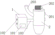
FIG. 1 is a schematic structural diagram of an embodiment;
FIG. 2 is a block diagram of a cross-section of a heating chamber according to an embodiment;
FIG. 3 is a sectional view of a reaction chamber according to an embodiment;
fig. 4 is a schematic structural diagram of the rear cover of the embodiment.
Reference numerals: 1. a heating box; 101. a panel; 102. an air extracting fan; 103. connecting a pipeline; 104. heating a tube; 105. a temperature sensor; 106. an electrically operated valve; 2. a reaction box; 201. An exhaust fan; 202. a motor; 203. a delivery pipe; 204. a rotating shaft; 205. fixing the rod; 206. A stirring paddle; 207. a filter screen; 208. an exhaust duct; 209. a discharge port; 3. a rear cover; 301. a screw hole; 302. a heat dissipation port; 303. a movable door; 304. a battery compartment; 305. and (4) a storage battery.
Detailed Description
The embodiment, a preheating device that aerobic fermentation does benefit to air flow, refer to fig. 1, there are two extraction fans 102 including the left side fixed mounting of heating cabinet 1, two exhaust duct 108 have been seted up on the right side of reaction box 2, exhaust duct 208 right side fixed mounting has exhaust fan 201, exhaust duct 108's inside fixed mounting has filter screen 207, the top welding of reaction box 2 has motor 202, the rotatory in-process of extraction fan 2 can extract outside gas, the gas of extraction heats and arrives reverse case 2 inside through the connecting tube nurse inside heating cabinet 1, can be outside with gaseous exhaust's device through the rotation of exhaust fan 201 after getting into reaction box 2, can guarantee the circulation of the inside air of equipment.
Referring to fig. 2, heating pipes 104 are fixedly mounted inside the heating box 1, the heating pipes 104 are distributed in a staggered manner, a temperature sensor 105 is fixedly mounted on the left side below the inside of the heating box 1, an electric valve 106 is movably connected to the middle of the right side of the heating box 1, and the heating pipes 104 can heat the entering gas.
Referring to fig. 3, there is pivot 204 inside top middle part swing joint of reaction box, the bottom welding of pivot 204 has dead lever 205, the both sides welding of dead lever 205 has a plurality of paddles 206, and inside the commodity circulation got into reaction box 3, the rotation of pivot 204 can drive dead lever 205 and paddle 206 and rotate, and paddle 206 can stir the commodity circulation that gets into at the pivoted in-process, makes the material disperse, and the heat air that the packing got into can be even preheats the commodity circulation.
In the specific implementation mode, a worker presses the panel to enable the suction fan 201 to enter a working state, the suction fan 201 entering the working state can extract gas into the heating box 1, the gas can be heated at the heating pipe 104 after extraction is completed, a working human body inputs material flow to be preheated into the reaction box 2 through the conveying pipe 203 in the heating process, the rotating shaft 204 can drive the fixing rod 205 and the stirring paddle 206 to rotate after the conveying is completed, the stirring paddle 206 can stir the entered material flow in the rotating process, the material flow can be conveyed into the reversing box 2 through the connecting pipe 103 after the gas heating is completed, the gas can preheat the material in stirring after the gas enters, the heat in the reaction box 2 can be discharged through the rotation of the exhaust fan 201 in the preheating process, the circulation of air in the equipment is ensured, the material can be discharged through the discharge hole 209 after the preheating is completed, the staff collects the material in discharge gate 209.
The present embodiment is only for explaining the present invention, and it is not limited to the present invention, and those skilled in the art can make modifications to the present embodiment without inventive contribution as required after reading the present specification, but all of them are protected by patent laws within the scope of the claims of the present invention.
Claims (7)
1. The utility model provides an aerobic fermentation does benefit to preheating device that air flows, includes heating cabinet (1) and reaction box (2), the intercommunication has connecting tube between heating cabinet (1) and reaction box (2), motor (202) have been welded at the top of reaction box (2), the left side intercommunication of reaction box (2) has conveyer pipe (203), its characterized in that: the left side fixed mounting of heating cabinet (1) has two extraction fans (102), two exhaust duct (208) have been seted up on the right side of reaction box (2), exhaust duct (208) right side fixed mounting has exhaust fan (201), the inside fixed mounting of exhaust duct (208) has filter screen (207).
2. The preheating device for facilitating air flow in aerobic fermentation according to claim 1, wherein: the inside fixed mounting of heating cabinet (1) has heating pipe (104), heating pipe (104) are the staggered distribution, the inside below left side fixed mounting of heating cabinet (1) has temperature-sensing appearance (105), the right side middle part swing joint of heating cabinet (1) has electrically operated valve (106).
3. The preheating device for facilitating air flow in aerobic fermentation according to claim 1, wherein: the inside top middle part swing joint of reaction box (2) has pivot (204), the bottom welding of pivot (204) has dead lever (205), the both sides welding of dead lever (205) has a plurality of stirring rakes (206).
4. The preheating device for facilitating air flow in aerobic fermentation according to claim 1, wherein: a discharge hole (209) is formed in the middle of the lower portion of the inside of the reaction box (2), and an electric valve (106) is movably connected to the left side of the lower portion of the inside of the reaction box (2).
5. The preheating device for facilitating air flow in aerobic fermentation according to claim 1, wherein: back lid (3) are installed to the rear end of heating cabinet (1), the rear end middle part top fixed mounting of back lid (3) has thermovent (302), the outside swing joint of thermovent (302) has dodge gate (303).
6. The preheating device for facilitating air flow in aerobic fermentation of claim 5, wherein: screw holes (301) are formed in the rear end of the rear cover (3), and four screw holes (301) are formed.
7. The preheating device for facilitating air flow in aerobic fermentation of claim 5, wherein: a battery bin (304) is fixedly arranged below the middle part of the rear end of the rear cover (3), and a storage battery is movably connected inside the battery bin (304).
Priority Applications (1)
| Application Number | Priority Date | Filing Date | Title |
|---|---|---|---|
| CN201921172561.4U CN210740717U (en) | 2019-07-24 | 2019-07-24 | Preheating device for facilitating air flow in aerobic fermentation |
Applications Claiming Priority (1)
| Application Number | Priority Date | Filing Date | Title |
|---|---|---|---|
| CN201921172561.4U CN210740717U (en) | 2019-07-24 | 2019-07-24 | Preheating device for facilitating air flow in aerobic fermentation |
Publications (1)
| Publication Number | Publication Date |
|---|---|
| CN210740717U true CN210740717U (en) | 2020-06-12 |
Family
ID=71010218
Family Applications (1)
| Application Number | Title | Priority Date | Filing Date |
|---|---|---|---|
| CN201921172561.4U Active CN210740717U (en) | 2019-07-24 | 2019-07-24 | Preheating device for facilitating air flow in aerobic fermentation |
Country Status (1)
| Country | Link |
|---|---|
| CN (1) | CN210740717U (en) |
Cited By (1)
| Publication number | Priority date | Publication date | Assignee | Title |
|---|---|---|---|---|
| CN114317256A (en) * | 2022-02-20 | 2022-04-12 | 重庆医科大学 | Medical science is culture dish for microbiology |
-
2019
- 2019-07-24 CN CN201921172561.4U patent/CN210740717U/en active Active
Cited By (1)
| Publication number | Priority date | Publication date | Assignee | Title |
|---|---|---|---|---|
| CN114317256A (en) * | 2022-02-20 | 2022-04-12 | 重庆医科大学 | Medical science is culture dish for microbiology |
Similar Documents
| Publication | Publication Date | Title |
|---|---|---|
| CN210740717U (en) | Preheating device for facilitating air flow in aerobic fermentation | |
| CN110551626B (en) | Temperature and humidity controllable horizontal solid-state fermentation tank | |
| CN206498923U (en) | A kind of Double shaft stirring self-loopa Vegetable drying machine | |
| CN114264125A (en) | Agricultural drying room with waste heat recovery function | |
| CN111704345A (en) | Pig manure drying equipment with waste heat recovery device | |
| CN201187877Y (en) | Warm-air machine for bathing room | |
| CN209652361U (en) | It is a kind of can be to the annealing furnace that heat is recycled | |
| CN108130272A (en) | Black garlic fermentation drying machine | |
| CN201997311U (en) | Still kettle with electromagnetic fan | |
| CN207180246U (en) | A kind of feed additive production drying machine | |
| CN216453268U (en) | Modular compact coffee roasting device | |
| CN208960540U (en) | A kind of central air conditioner cooling system apparatus for eliminating sludge | |
| CN212431674U (en) | Fodder drying device with waste heat recovery function | |
| CN208846878U (en) | Waste residue drying device is used in a kind of production of converted starch | |
| CN209412218U (en) | Kitchen garbage fermentation heating system | |
| CN209726395U (en) | A kind of energy-saving and environment-friendly air conditioning apparatus | |
| CN208317132U (en) | A kind of pcb board oven energy saver | |
| CN102091568A (en) | Autoclave with electromagnetic fan | |
| CN2495942Y (en) | Means for giving hot water by utilizing waste heat from air conditioner | |
| CN110966847A (en) | Poultry is bred and uses fodder drying device based on PLC control | |
| CN220981827U (en) | Gelatin stoving heated air circulation equipment | |
| CN213396447U (en) | Maize drying device for feed processing | |
| CN206930104U (en) | A kind of master-batch drying device | |
| CN210329244U (en) | Duck oil cooling device | |
| CN220541607U (en) | Medical material constant temperature drying barrel |
Legal Events
| Date | Code | Title | Description |
|---|---|---|---|
| GR01 | Patent grant | ||
| GR01 | Patent grant |