CN210739662U - Sliding extrusion type clamping and pressing thread straight-through reducing joint - Google Patents
Sliding extrusion type clamping and pressing thread straight-through reducing joint Download PDFInfo
- Publication number
- CN210739662U CN210739662U CN201921038069.8U CN201921038069U CN210739662U CN 210739662 U CN210739662 U CN 210739662U CN 201921038069 U CN201921038069 U CN 201921038069U CN 210739662 U CN210739662 U CN 210739662U
- Authority
- CN
- China
- Prior art keywords
- joint
- main part
- screw thread
- clamping
- thick bamboo
- Prior art date
- Legal status (The legal status is an assumption and is not a legal conclusion. Google has not performed a legal analysis and makes no representation as to the accuracy of the status listed.)
- Active
Links
Images


Abstract
The utility model discloses a refrigeration pipe technical field a smooth crowded formula card presses direct reducing of screw thread to connect, including the return bend that the material is red copper, return bend both ends axis aligns each other, the one end welding of return bend has the joint main part, the return bend other end is connected with the screw thread that has interior tooth screw thread and receives son, still including the cover body and nested, cover internal chamber and joint main part outer wall joint make the inside extrusion deformation of joint main part, realize the sealing connection to the inside and outside wall of red copper pipe, the joint main part, the cover body, the material of nested and screw thread son is the brass, the inside quick loose joint of tooth spiro union connects the external diameter different in inserting red copper pipe external diameter of joint main part and the screw thread son. The utility model discloses do not use naked light welding, solve the easy rust problem of steel material card pressure pipe fitting, make the installation of the direct pipe of the coaxial different external diameters of switching and the refrigeration pipe of quick loose joint convenient more fast, the anti potential corrosion of brass material can not rust.
Description
Technical Field
The utility model relates to a refrigeration pipeline technical field specifically is a smooth crowded formula card presses straight reducing of screw to connect.
Background
The connection between most of refrigeration pipe fittings is realized by using a traditional welding mode so far, and joints are needed when different pipe diameters are met, manual flaring is needed sometimes during installation, the conditions of poor sealing performance and the like are often caused due to uneven wall thickness, the process of the traditional welding mode is complicated, technical workers need to hold a special welding skill certificate to be on duty, and the application and popularization of the refrigeration pipe fittings are limited.
The open flame welding process has complex technical requirements, is easy to corrode and rust, and cannot quickly and conveniently realize the coaxial connection of the straight-through pipe with different outer diameters and the quick loose joint.
Based on this, the utility model designs a smooth crowded formula card presses direct reducing of screw to connect to solve above-mentioned problem.
SUMMERY OF THE UTILITY MODEL
An object of the utility model is to provide a smooth crowded formula card is pressed straight reducing of screw and is connected to solve the numerous and diverse technical requirement height of naked light welding process that provides in the above-mentioned background art, be corroded easily and rust, the direct pipe of the different external diameters of convenient realization fast and quick loose joint of the problem of coaxial coupling that can not connect.
In order to achieve the above object, the utility model provides a following technical scheme: a sliding extrusion type clamping-pressing thread straight-through reducing joint comprises a bent pipe made of red copper, wherein the axes of two ends of the bent pipe are aligned, one end of the bent pipe is welded with a clamping main body, the other end of the bent pipe is provided with a flared bell mouth which is outwards unfolded, the outer wall of the other end of the bent pipe is connected with a thread acceptor which is limited and sealed by the bell mouth and provided with an inner thread in a sliding manner, the sliding joint further comprises a sleeve body and a nesting sleeve which is inserted into the red copper pipe, the clamping main body is inwards extruded and deformed by clamping the inner cavity of the sleeve body and the outer wall of the clamping main body, the clamping main body is deformed and matched with the nesting sleeve body to realize the sealing connection of the inner wall and the outer wall of the red copper pipe, the sleeve body is extruded and fused by extrusion of a clamping clamp during working, the convex part of a clamping cylinder is pushed, materials are shaped from the concave part of the inner wall, the, the quick loose joint comprises a joint main body, a sleeve body and a nested structure, wherein the joint main body, the sleeve body and the nested structure are all made of lead brass HPb60-2, the thread nut is made of lead brass HPb59-1, and the outer diameter of a red copper pipe inserted into the joint main body is different from the outer diameter of a quick loose joint of a thread nut in the thread nut.
Preferably, the joint main part comprises a main part section of thick bamboo, a joint section of thick bamboo and the joint clamping ring of coaxial interlinkage as an organic whole, the joint outer wall that the clamping ring is located a main part section of thick bamboo and a joint section of thick bamboo is outside protruding inner wall sunken, a main part section of thick bamboo and return bend one end welding are even integrative, the wall thickness of a joint section of thick bamboo is 0.6-1.0mm, the middle part of a joint section of thick bamboo is outside protruding, the external diameter of the protruding department in middle part of the free end of clamping ring is less than a joint section of thick bamboo external diameter of protruding department in middle part to clamping ring of a joint section of thick bamboo.
Preferably, the inner diameter of the sleeve body is in interference fit with the outer diameter of a convex part from the free end to the middle part of the clamping cylinder, the wall thickness of the sleeve body is 2.3-3.2mm, an inclined angle of 8-10 degrees is outwards arranged at the inner diameter of one end, close to the clamping main body, of the sleeve body, and an inclined angle of 5-7 degrees is inwards arranged at the inner diameter of the other end of the sleeve body.
Preferably, the length of the clamping cylinder is greater than that of the sleeve body.
Preferably, the screw thread is received son appearance and is the regular hexagon, the screw thread is received son inside and is constituteed for coaxial internal thread hole and interior through-hole, and internal thread hole internal diameter is greater than interior through-hole internal diameter, internal thread hole and interior through-hole linking department be provided with horn mouth complex slope.
Compared with the prior art, the beneficial effects of the utility model are that: the utility model discloses do not use naked light welding, solve the easy rust problem of steel material card pressure pipe fitting, make the coaxial direct pipe of switching and the installation of the refrigeration pipe of the quick loose joint of different external diameters convenient more fast, the brass material is anti potential corrosion, can not rust, and bulk strength is greater than that traditional pipe fitting is more withstand voltage, uses the copper product material circulated, environmental protection more.
Drawings
In order to more clearly illustrate the technical solutions of the embodiments of the present invention, the drawings used in the description of the embodiments will be briefly introduced below, and it is obvious that the drawings in the following description are only some embodiments of the present invention, and it is obvious for those skilled in the art that other drawings can be obtained according to these drawings without creative efforts.
FIG. 1 is a schematic structural view of the present invention;
FIG. 2 is a half-sectional view of the elbow of the present invention;
FIG. 3 is a half sectional view of the clamping main body of the present invention;
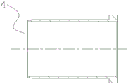
FIG. 4 is a half-sectional view of the sheath body of the present invention;
fig. 5 is a half-sectional view of the nesting of the present invention;
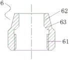
fig. 6 is a half-sectional view of the screw nut of the present invention.
Fig. 7 is a schematic view of the clamping main body and the sleeve body of the present invention.
In the drawings, the components represented by the respective reference numerals are listed below:
1. bending the pipe; 11. a bell mouth; 2. clamping the main body; 21. a main body barrel; 22. a clamping cylinder; 23. clamping a pressure ring; 3. a sleeve body; 4. nesting; 5. a red copper tube; 6. a screw thread is arranged; 61. an internally threaded bore; 62. an inner through hole; 63. the slope is inclined.
Detailed Description
The technical solutions in the embodiments of the present invention will be described clearly and completely with reference to the accompanying drawings in the embodiments of the present invention, and it is obvious that the described embodiments are only some embodiments of the present invention, not all embodiments. Based on the embodiments of the present invention, all other embodiments obtained by a person of ordinary skill in the art without creative efforts belong to the protection scope of the present invention.
One specific application of this embodiment is:
1. the brass pipe fitting is turned in a numerical control mode to form a thin-wall structure with a certain geometric shape, and the brass pipe fitting and the red copper pipe fitting are connected in a sealed and fastened mode through mutual extrusion between the brass pipe fitting and a special sliding and extruding caliper.
2. One end of the horn mouth with the internal thread can be in butt joint with equipment quickly to realize connection sealing and firmness.
3. The whole connection process is carried out at two ends:
(1) confirming whether the sleeve body 3 is sleeved on the clamping main body 2 or not, and carrying out subsequent steps after no error exists;
(2) firstly, scraping burrs at the inner port of the connected red copper tube 5 by using a scraper, and polishing the length of an excircle by using wire drawing cloth for visual inspection;
(3) inserting the nesting 4 into the hole of the connected red copper tube 5, wherein the outer wall of one end of the nesting 4 is provided with a convex block with the same outer diameter as the red copper tube 5;
(4) inserting the connected copper tube 5 and the nest 4 into an inner hole of a clamping cylinder 22 in the clamping main body 2 until the copper tube is blocked, enabling the copper tube 5 to be in clearance fit with the inner hole of the clamping cylinder 22, and drawing marks at the joint of the outer wall of the copper tube 5 and the free end of the clamping cylinder 22 to confirm the gluing area;
(5) the sleeve body 3 is arranged on the outer wall of the connected copper tube 5, and sealant is coated on the outer wall of the copper tube 5 in a circle within the range of drawing lines;
(6) after the glue is coated, the copper tube 5 to be connected and the nest 4 are inserted into an inner hole of the clamping cylinder 22 in the clamping main body 2 by rotating 180 degrees;
(7) the cover body 3 sleeved with the outer wall of the copper tube 5 is sleeved on the outer wall of the clamping cylinder 22 in the clamping main body 2, and the cover body 3 is abutted to the bulge in the middle of the clamping cylinder 22 to stop going forward continuously due to the interference fit between the inner diameter of the cover body 3 and the outer diameter of the bulge from the free end of the clamping cylinder 22 to the middle.
(8) The special sliding extrusion type clamping and pressing clamp is aligned to the tail end side wall of the clamping and pressing ring 23 in the clamping main body 2 and the sleeve body 3 which are far away from each other, the clamping and pressing clamp is adjusted to a proper width, the clamping and pressing clamp is started to tightly clamp the four parts, the arrow direction in the drawing is the clamping and pressing direction, the perpendicular surface of the arrow is the clamping and pressing end face, the sleeve body 3 extrudes the middle bulge of the clamping cylinder 22, so that the sleeve body 3 is continuously close to the clamping and pressing ring 23, the bulge part from the free end to the middle part of the clamping cylinder 22 is extruded and tightly abutted with the red copper tube 5 to realize fixation, the red copper tube 5 is softer relative to the clamping cylinder 22 of brass, the red copper tube 5 is extruded and deformed to be beneficial to tight attachment, the red copper tube 5 is clamped inside and outside the clamping cylinder 22 of the nesting 4 and is matched with sealant to realize sealing, because the inner diameter of the sleeve body 3 is in interference, so that the convex part in the middle of the clamping cylinder 22 is extruded inwards to the wall of the clamping cylinder 22 of the clamping and pressing ring 23, and the sleeve body 3 and the clamping cylinder 22 are fixed.
(9) With the inside internal thread hole 61 of screw thread son 6 and the quick loose joint articulate of being connected, because internal thread hole 61 internal diameter is greater than interior through-hole 62 internal diameter, make connected quick loose joint one end and the 1 one end butt of return bend, make the quick loose joint of being connected and the relatively fixed of return bend 1, the slope 63 in the screw thread son 6 is just laminated with the horn mouth 11 of return bend 1 one end this moment, continue to remove screw thread son 6, make slope 63 continue to be close to laminating horn mouth 11, horn mouth 11 is the material for the screw thread son 6 of the relative brass material of red copper softer, make horn mouth 11 warp improve with the sealed effect of laminating of slope 63 in the screw thread son 6.
In the description herein, references to the description of "one embodiment," "an example," "a specific example," etc., mean that a particular feature, structure, material, or characteristic described in connection with the embodiment or example is included in at least one embodiment or example of the invention. In this specification, the schematic representations of the terms used above do not necessarily refer to the same embodiment or example. Furthermore, the particular features, structures, materials, or characteristics described may be combined in any suitable manner in any one or more embodiments or examples.
The preferred embodiments of the present invention disclosed above are intended only to help illustrate the present invention. The preferred embodiments are not intended to be exhaustive or to limit the invention to the precise embodiments disclosed. Obviously, many modifications and variations are possible in light of the above teaching. The embodiments were chosen and described in order to best explain the principles of the invention and its practical applications, to thereby enable others skilled in the art to best understand the invention for and utilize the invention. The present invention is limited only by the claims and their full scope and equivalents.
Claims (5)
1. The utility model provides a smooth crowded formula card presses straight reducing of screw thread to connect, includes that the material is return bend (1) of red copper, its characterized in that: the axis of elbow pipe (1) both ends aligns, the one end welding of elbow pipe (1) has joint main part (2), elbow pipe (1) other end is provided with outside flared horn mouth (11), and elbow pipe (1) other end outer wall sliding connection have by horn mouth (11) spacing sealed screw thread receive son (6) that have interior tooth screw thread, still including the cover body (3) and insert nested (4) of copper pipe (5) inside, cover body (3) inner chamber and joint main part (2) outer wall joint make joint main part (2) inwards extrusion deformation, joint main part (2) warp and nested (4) cooperation realize the sealing connection to copper pipe (5) inside and outside wall, the material of joint main part (2), cover body (3), nested (4) is lead brass HPb60-2, the material of screw thread receive son (6) is lead brass HPb59-1, the outer diameter of a copper tube (5) inserted into the clamping main body (2) is different from the outer diameter of a quick loose joint of the inner thread screw joint of the thread containing unit (6).
2. The sliding and extruding type clamping and pressing threaded straight-through reducing joint as claimed in claim 1, wherein: joint main part (2) are become by the coaxial main part section of thick bamboo that links into an organic whole of (21), a joint section of thick bamboo (22) and card clamping ring (23) and constitute, clamping ring (23) are located the outside protruding inner wall in junction outer wall of a main part section of thick bamboo (21) and a joint section of thick bamboo (22) and are sunken, a main part section of thick bamboo (21) and return bend (1) one end welded connection are integrative, the wall thickness of a joint section of thick bamboo (22) is 0.6-1.0mm, the middle part of a joint section of thick bamboo (22) is outside protruding, clamping ring (23) free end is less than a joint section of thick bamboo (22) external diameter to the joint section of thick bamboo (22) of clamping ring (23) of protruding department in middle part to the protruding department in middle.
3. The sliding and extruding type clamping and pressing threaded straight-through reducing joint as claimed in claim 2, wherein: the inner diameter of the sleeve body (3) is in interference fit with the outer diameter of a free end of the clamping cylinder (22) to a middle protruding part, the wall thickness of the sleeve body (3) is 2.3-3.2mm, an inclined angle of 8-10 degrees is outwards arranged at the inner diameter of one end, close to the clamping main body (2), of the sleeve body (3), and an inclined angle of 5-7 degrees is inwards arranged at the inner diameter of the other end of the sleeve body (3).
4. The sliding and extruding type clamping and pressing threaded straight-through reducing joint as claimed in claim 2, wherein: the length of the clamping cylinder (22) is greater than that of the sleeve body (3).
5. The sliding and extruding type clamping and pressing threaded straight-through reducing joint as claimed in claim 1, wherein: the appearance of screw thread son (6) is regular hexagon, the screw thread is inside to constitute for coaxial internal thread hole (61) and interior through-hole (62) in son (6), and internal thread hole (61) internal diameter is greater than interior through-hole (62) internal diameter, internal thread hole (61) and interior through-hole (62) link up the department be provided with bellmouth (11) complex slope (63).
Priority Applications (1)
| Application Number | Priority Date | Filing Date | Title |
|---|---|---|---|
| CN201921038069.8U CN210739662U (en) | 2019-07-05 | 2019-07-05 | Sliding extrusion type clamping and pressing thread straight-through reducing joint |
Applications Claiming Priority (1)
| Application Number | Priority Date | Filing Date | Title |
|---|---|---|---|
| CN201921038069.8U CN210739662U (en) | 2019-07-05 | 2019-07-05 | Sliding extrusion type clamping and pressing thread straight-through reducing joint |
Publications (1)
| Publication Number | Publication Date |
|---|---|
| CN210739662U true CN210739662U (en) | 2020-06-12 |
Family
ID=70982306
Family Applications (1)
| Application Number | Title | Priority Date | Filing Date |
|---|---|---|---|
| CN201921038069.8U Active CN210739662U (en) | 2019-07-05 | 2019-07-05 | Sliding extrusion type clamping and pressing thread straight-through reducing joint |
Country Status (1)
| Country | Link |
|---|---|
| CN (1) | CN210739662U (en) |
Cited By (2)
| Publication number | Priority date | Publication date | Assignee | Title |
|---|---|---|---|---|
| WO2022033479A1 (en) * | 2020-08-14 | 2022-02-17 | 浙江盾安人工环境股份有限公司 | Tube, tube assembly and heat exchanger |
| CN114923049A (en) * | 2022-03-31 | 2022-08-19 | 华能国际电力股份有限公司德州电厂 | Purging conversion connecting device |
-
2019
- 2019-07-05 CN CN201921038069.8U patent/CN210739662U/en active Active
Cited By (3)
| Publication number | Priority date | Publication date | Assignee | Title |
|---|---|---|---|---|
| WO2022033479A1 (en) * | 2020-08-14 | 2022-02-17 | 浙江盾安人工环境股份有限公司 | Tube, tube assembly and heat exchanger |
| CN114923049A (en) * | 2022-03-31 | 2022-08-19 | 华能国际电力股份有限公司德州电厂 | Purging conversion connecting device |
| CN114923049B (en) * | 2022-03-31 | 2024-04-19 | 华能国际电力股份有限公司德州电厂 | Purging conversion connecting device |
Similar Documents
| Publication | Publication Date | Title |
|---|---|---|
| CN210739662U (en) | Sliding extrusion type clamping and pressing thread straight-through reducing joint | |
| CN200972038Y (en) | Clamp for connecting joint of plastic pipe and metal pipe | |
| US20100225109A1 (en) | Tube connector | |
| CN204114410U (en) | fluid coupling | |
| CN210739661U (en) | Sliding-extrusion type clamping-pressing straight-through reducing joint | |
| CN210739693U (en) | Sliding extrusion type thread conversion elbow | |
| CN210398001U (en) | Pipeline connection structure convenient to loading and unloading | |
| CN211738365U (en) | Sliding extrusion type clamping elbow | |
| CN211475147U (en) | Spiral corrugated pipe joint | |
| CN102401195A (en) | Stainless steel reducing pipe and machining method thereof | |
| CN1271068A (en) | Extruded joint pipe fittings | |
| CN201209718Y (en) | Tube end structure for enhancing sealing performance and assembling performance | |
| CN209100831U (en) | Assembling pipe joint | |
| CN102734574A (en) | Pipe joint component and safety locking pipeline connection system comprising same | |
| CN211315442U (en) | Pipeline connecting system for fluid conveying | |
| CN202646989U (en) | Pipe connector assembly and safe locking pipeline connecting system comprising same | |
| CN207621542U (en) | A kind of snap ring positioning formula gas bellows | |
| CN2450492Y (en) | Internal thread locking connector | |
| CN210770766U (en) | Quick joint for pipeline | |
| CN212361096U (en) | Sliding and extruding type ball valve for refrigeration | |
| CN219282640U (en) | Pipe fitting connection structure | |
| CN214789710U (en) | Plastic pipeline connector and pipeline connecting device | |
| CN218378277U (en) | A kind of novel pipe fitting | |
| CN107906286A (en) | A kind of snap ring positions formula gas bellows | |
| CN217440451U (en) | Joint for pipe connection and connection structure of pipe and joint |
Legal Events
| Date | Code | Title | Description |
|---|---|---|---|
| GR01 | Patent grant | ||
| GR01 | Patent grant |