Compound test device of liquid fertilizer
Technical Field
The utility model relates to a compound test device of liquid fertilizer belongs to liquid fertilizer scientific research and production technical field.
Background
The liquid fertilizer belongs to one kind of water-soluble fertilizer, has the main functions of meeting a water-fertilizer integrated agricultural planting system, not only supplementing nutrition for crops, but also supplementing moisture, and nutrient elements can be well absorbed by plant roots or leaf surfaces through water coupling, so that the utilization rate of the fertilizer is integrally improved, and simultaneously along with the policies of implementing agricultural green development and weight and drug reduction in China, a large number of liquid fertilizer products are rapidly emerged in the market in recent years, and make due contribution to the agricultural green development in China.
The quality or stability of liquid fertilizer products in the market is not uniform, one of the main reasons is the problem of production technology control, the process requires stability tests on liquid fertilizer product formulations with relevant standards, especially compound reaction tests, and the problems of different reaction degrees, precipitation, floccule formation, layering and the like of different raw materials need repeated tests.
Based on above, if can realize experimental better control of liquid fertilizer complex formulation effect and stable quick test, avoid the experimental not enough of little dose, also do not increase large-scale reaction system simultaneously, reduce the raw materials loss that the production scientific research experiment leads to, then the production or the scientific research experimental efficiency of improvement liquid fertilizer that can be better, to above problem, we propose a liquid fertilizer complex formulation test device.
SUMMERY OF THE UTILITY MODEL
The to-be-solved technical problem of the utility model is to overcome prior art's defect, provide a liquid fertilizer compound test device.
In order to solve the technical problem, the utility model provides a following technical scheme:
the utility model relates to a compound test device of liquid fertilizer, a serial communication port, which comprises a tank body, insert perpendicularly on the jar body top and install the blast pipe, storage regulation and control mechanism is installed to blast pipe one side, install rabbling mechanism on the inner wall of storage regulation and control mechanism lower extreme jar body top, fixed mounting has temperature sensor on the jar body lateral wall of rabbling mechanism one side, fixed mounting has the heating bottom plate on the inner wall of temperature sensor lower extreme jar body bottom, install three sample valve on a heating bottom plate side jar body opposite side wall, fixed mounting has the baiting valve on the jar body lateral wall of sample valve lower extreme, baiting valve one side jar body lateral wall upper end fixed mounting has the control display.
As a preferred technical scheme of the utility model, storage regulation and control mechanism includes transparent material section of thick bamboo, fixed mounting has the scale on the transparent material section of thick bamboo lateral wall, the perpendicular fixed mounting of transparent material section of thick bamboo lower extreme has the unloading pipe, just the unloading pipe lower extreme inserts jar body top perpendicularly, fixed mounting has the unloading valve on the unloading pipe.
As a preferred technical scheme of the utility model, rabbling mechanism includes the motor, the perpendicular fixed mounting in motor bottom is on jar body top inner wall, motor output fixed connection (mixing) shaft, just equal symmetry fixed mounting has the stirring rake on the (mixing) shaft lower extreme lateral wall.
As an optimal technical scheme of the utility model, jar side wall has been seted up three trompil diameter and is 2cm, just three trompil is located jar 1/6, 1/2 and 5/6 position respectively on the jar side wall and all is connected with the sample valve.
As an optimal technical scheme of the utility model, motor, temperature sensor and heating bottom plate all with control display electric connection.
The utility model discloses the beneficial effect who reaches is: the utility model relates to a liquid fertilizer compound test device, through placing the material in the transparent material barrel and according to the scale on the transparent material barrel, and then control the opening and closing of unloading valve and regulate and control the material input, and through controlling the display control starter motor, the motor operation drives the (mixing) shaft and the stirring rake to rotate, carry out intensive mixing stirring to its material and water, improved the mixed effect, and through controlling display control regulation temperature sensor and heating bottom plate, make it regulate and control the temperature in the appointed scope, the safety of device has been guaranteed, and through the sampling valve of jar body 1/6, 1/2 and 5/6 position difference fixed mounting respectively, conveniently gather and detect the liquid fertilizer of different degree of depth in its jar body, compared with the existing device, the device simple structure, the operation is convenient, can carry out size design and installation according to the production and scientific research experiment needs of different liquid fertilizers, the test control and test requirements of different liquid fertilizer products are met, the compounding test efficiency of the liquid fertilizer is improved, and the compounding test period and the raw material cost required by the test are reduced.
Drawings
The accompanying drawings are included to provide a further understanding of the invention, and are incorporated in and constitute a part of this specification, illustrate embodiments of the invention, and together with the description serve to explain the invention and not to limit the invention.
In the drawings:
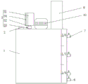
fig. 1 is a schematic view of the overall structure of the present invention;
fig. 2 is a schematic front view of the present invention;
fig. 3 is a schematic diagram of the circuit structure of the present invention.
In the figure: 1. a tank body; 2. an exhaust pipe; 3. a material storage regulating mechanism; 31. a transparent material cylinder; 32. a discharging pipe; 33. a discharge valve; 34. a scale bar; 4. a stirring mechanism; 41. a motor; 42. a stirring shaft; 43. a stirring paddle; 5. a temperature sensor; 6. heating the soleplate; 7. a sampling valve; 8. a discharge valve; 9. and controlling the display.
Detailed Description
The preferred embodiments of the present invention will be described in conjunction with the accompanying drawings, and it will be understood that they are presented herein only to illustrate and explain the present invention, and not to limit the present invention.
Examples
As shown in fig. 1-3, a liquid fertilizer compound test device, including a jar body 1, 1 top of jar body is gone up and is inserted perpendicularly and install blast pipe 2, 2 one sides of blast pipe are installed storage regulation and control mechanism 3, install rabbling mechanism 4 on 3 lower extreme jar body 1 top inner walls of storage regulation and control mechanism, fixed mounting has temperature sensor 5 on 4 one side jar body 1 lateral walls of rabbling mechanism, fixed mounting has heating bottom plate 6 on 5 lower extreme jar body 1 bottom inner walls of temperature sensor, 6 one side jar body opposite side wall mounting of heating bottom plate has three sample valve 7, fixed mounting has baiting valve 8 on 7 lower extreme jar body 1 lateral walls of sample valve, 8 one side jar body 1 lateral wall upper end fixed mounting of baiting valve has control display 9.
The storage regulating mechanism 3 comprises a transparent material barrel 31, a scale 34 is fixedly mounted on the outer side wall of the transparent material barrel 31, a blanking pipe 32 is vertically and fixedly mounted at the lower end of the transparent material barrel 31, the lower end of the blanking pipe 32 is vertically inserted into the top end of the tank body 1, and a blanking valve 33 is fixedly mounted on the blanking pipe 32.
Wherein, rabbling mechanism 4 includes motor 41, and the perpendicular fixed mounting in motor 41 bottom is on jar body 1 top inner wall, and motor 41 output fixed connection (mixing) shaft 42, and equal symmetrical fixed mounting has stirring rake 43 on the (mixing) shaft 42 lower extreme lateral wall.
Wherein, jar body 1 lateral wall is seted up three trompil diameter and is 2cm, and three trompil on jar body 1 lateral wall is located jar body 1/6, 1/2 and 5/6 position respectively and all is connected with sample valve 7.
Wherein, the motor 41, the temperature sensor 5 and the heating bottom plate 6 are all electrically connected with the control display 9.
Specifically, when the utility model is used, firstly, the motor 41, the temperature sensor 5, the heating bottom plate 6 and the control display 9 are all powered on, the model of the temperature sensor 5 is SDC-2000, the model of the heating bottom plate 6 is cast aluminum 2KW, the model of the control display 9 is Siemens S7-200, the materials are placed in the transparent material barrel 31 and are regulated and controlled according to the scale 34 on the transparent material barrel 31 by controlling the opening and closing of the blanking valve 33, the motor 41 is controlled and started by controlling the display 9, the motor 41 operates to drive the stirring shaft 42 and the stirring paddle 43 to rotate, the materials and water are fully mixed and stirred, the mixing effect is improved, the temperature sensor 5 and the heating bottom plate 6 are detected and regulated and controlled by controlling the display 9, the temperature is controlled in a specified range, and the safety of the reaction in the tank body 1 is ensured, and through jar body 1/6, 1/2 and 5/6 position department respectively fixed mounting's sampling valve 7, gather the detection to different degree of depth liquid fertilizer in its jar body 1, discharge through baiting valve 8 after the detection is accomplished, this device simple structure, the simple operation, can carry out size design and installation according to the production of different liquid fertilizer and scientific research experimental needs, satisfy the experimental control and the test requirement of different liquid fertilizer products, the compound experimental efficiency of liquid fertilizer has been improved, the required raw materials cost of compound experimental cycle and experiment has been reduced, until accomplishing whole work order.
Finally, it should be noted that: although the present invention has been described in detail with reference to the foregoing embodiments, it will be apparent to those skilled in the art that modifications may be made to the embodiments described in the foregoing embodiments, or equivalents may be substituted for elements thereof. Any modification, equivalent replacement, or improvement made within the spirit and principle of the present invention should be included in the protection scope of the present invention.