Novel box-type substation
Technical Field
The utility model relates to a transformer substation technical field specifically is a novel box-type substation.
Background
The box-type transformer substation is a factory prefabricated indoor and outdoor compact distribution equipment integrating high-voltage switch equipment, distribution transformer and low-voltage distribution equipment according to a certain wiring scheme, organically combines the functions of transformer voltage reduction, low-voltage distribution and the like together, is installed in a moistureproof, antirust, dustproof, rat-proof, fireproof, antitheft, heat-insulating, totally-enclosed and movable steel structure box, and is particularly suitable for urban network construction and transformation.
The box inner space of the existing box type transformer substation is small, a large amount of heat generated by equipment cannot be dissipated outside quickly due to the radiating plate installed on the side face of the transformer substation, the heat is gathered inside the equipment, and the operation of the equipment can be influenced due to overhigh temperature.
Secondly current box-type substation, the heating panel that the box side set up is fixed in the position nearer from ground for better radiating effect more, easily leads to external rainwater to spatter inside the box, perhaps the dust gets into, influences equipment and uses, and device self must set up heat dissipation channel, otherwise can influence the normal operating of equipment.
SUMMERY OF THE UTILITY MODEL
Aiming at the defects of the prior art, the utility model provides a novel box-type substation, which has the advantages of rapid heat dissipation and small external influence, solves the problems of the prior box-type substation that the internal space of the box body is small, the heat dissipation plate is embedded on the side surface of the substation, a large amount of heat generated by equipment cannot be rapidly dissipated, the heat is gathered in the equipment, and the operation of the equipment is influenced by overhigh temperature; the lower heat dissipation plate that can lead to external rainwater to spatter inside the box or the dust gets into off the ground, influences equipment use problem.
The utility model provides a following technical scheme: the utility model provides a novel box-type substation, includes the base, the heel post has all been welded to the upper end both sides of base, four are installed to the heel post, and four heel posts are divided into two sets of front and back, leading group the top fixed mounting that is located the base between the heel post has the chamber door, four the top fixed mounting of heel post has the bottom plate, the bottom surface both sides fixed mounting of bottom plate has the draw-in groove, be connected through the draw-in groove between heel post and the bottom plate, the upper surface outer fringe of bottom plate all inclines fixed mounting has the guide plate, four groups are installed to the guide plate, four groups the top movable mounting of guide plate has the apron, the equal fixed mounting in bottom four corners department of apron has the bracing piece, the outside movable mounting of bracing piece has the movable sleeve.
Preferably, the plate body of apron is the recess form, solar panel and four groups of pressure sensors are installed to the upper surface mosaic of apron, solar panel fixes in the middle of the apron, four groups pressure sensors distribute in the apron four corners.
Preferably, the bottom of the supporting rod is fixedly provided with a linear motor, the linear motor is arranged inside the movable sleeve, and the pressure sensor is connected with the linear motor through a wire.
Preferably, the lower surface of apron corresponds solar panel and installs battery and motor, the outside at the motor is installed to the battery, the lower extreme of motor is rotated and is installed the transfer line.
Preferably, an arc-shaped end is installed at the bottom of the transmission rod, a clamp is sleeved between the bottom of the transmission rod and the arc-shaped end, two sets of fan blades are welded on the outer side of the clamp, and the two sets of fan blades are fixed between the support rods.
Preferably, the outer surface of the guide plate is provided with water diversion stripes, the inside of the bottom plate is hollow, and the hollow part of the bottom plate corresponds to the fan blades.
Compared with the prior art, the utility model discloses possess following beneficial effect:
1. this novel box-type substation, through bracing piece rebound in the draw-in groove, with apron jack-up, the flabellum of apron below removes outside the device, be located between apron and the bottom plate, external wind-force blows to the flabellum, the flabellum can rotate, provide wind-force downwards, accelerate the inside circulation of air of transformer substation, the incasement constantly carries out the cold air decline, the ascending exhaust circulation of hot-air, the exchange capacity who utilizes cold and hot air current dispels the heat, the heat dissipation is fast, swing joint through anchor clamps and transfer line, bottom arc end supports, when making the fan rotate, can be according to wind direction skew angle, wind-force is received to the at utmost, the fan exchanges with the inside air of equipment again, the radiating effect is.
2. This novel box-type substation, through four pressure sensors on apron surface, the pressure that raindrops brought when can respond to simultaneously raining, to linear electric motor transmission signal, linear electric motor operation is withdrawed the bracing piece, and the apron cover is at the guide plate top, and the rainwater passes through the guide plate and flows, can not get into the operation of equipment internal disturbance electrical apparatus, has guaranteed the radiating efficiency and can not make the device inside wet or advance the dust, guarantees that the operation of transformer substation is stable.
Drawings
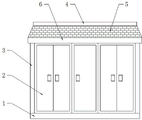
FIG. 1 is a schematic structural view of the present invention;
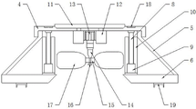
FIG. 2 is a schematic view of the internal structure between the bottom plate and the cover plate of the present invention;
fig. 3 is a schematic perspective view of the structure of the upper surface of the cover plate of the present invention.
In the figure: 1. a base; 2. a box door; 3. a load-bearing column; 4. a cover plate; 5. a baffle; 6. a base plate; 7. a movable sleeve; 8. a support bar; 9. a linear motor; 10. a card slot; 11. a solar panel; 12. a battery; 13. a motor; 14. a transmission rod; 15. a clamp; 16. an arc-shaped end; 17. a fan blade; 18. a pressure sensor.
Detailed Description
The technical solutions in the embodiments of the present invention will be described clearly and completely with reference to the accompanying drawings in the embodiments of the present invention, and it is obvious that the described embodiments are only some embodiments of the present invention, not all embodiments. Based on the embodiments in the present invention, all other embodiments obtained by a person skilled in the art without creative work belong to the protection scope of the present invention.
Referring to fig. 1-3, a novel box-type substation comprises a base 1, wherein two sides of the upper end of the base 1 are welded with four bearing columns 3, so as to ensure the stable structure of the substation, four bearing columns 3 are divided into a front group and a rear group, a box door 2 is fixedly arranged above a base 1 between the front group of bearing columns 3, a bottom plate 6 is fixedly arranged at the top of the four bearing columns 3, clamping grooves 10 are fixedly arranged at two sides of the bottom surface of the bottom plate 6, the bearing columns 3 are connected with the bottom plate 6 through the clamping grooves 10, guide plates 5 are fixedly arranged on the outer edges of the upper surface of the bottom plate 6 in an inclined manner, and four groups of guide plates 5 are arranged on the guide plates 5, the rainwater drainage device is used for rainwater drainage, a cover plate 4 is movably mounted at the tops of four groups of flow guide plates 5, supporting rods 8 are fixedly mounted at four corners of the bottom of the cover plate 4, a movable sleeve 7 is movably mounted on the outer side of each supporting rod 8, and the bottom of each movable sleeve 7 is fixedly mounted on the upper surface of a bottom plate 6.
Further, the plate body of the cover plate 4 is groove-shaped, the solar panel 11 and four groups of pressure sensors 18 are embedded in the upper surface of the cover plate 4, the solar panel 11 is fixed in the middle of the cover plate 4, the four groups of pressure sensors 18 are distributed at four corners of the cover plate 4, the solar panel 11 is used for absorbing light energy to generate electricity, and the four groups of pressure sensors 18 can simultaneously sense whether the solar panel is pressed or not to determine whether the outside is raining or not.
Further, the bottom of the supporting rod 8 is fixedly provided with a linear motor 9, the linear motor 9 is installed inside the movable sleeve 7, a pressure sensor 18 is connected with the linear motor 9 through a lead, the pressure sensor 18 controls the linear motor 9 in the device, and the linear motor 9 can control the supporting rod 8 to move linearly inside the movable sleeve 7 when in operation.
Further, the lower surface of the cover plate 4 is provided with a battery 12 and a motor 13 corresponding to the solar panel 11 for storing electric energy, the battery 12 is arranged outside the motor 13, and the lower end of the motor 13 is rotatably provided with a transmission rod 14.
Further, an arc-shaped end 16 is installed at the bottom of the transmission rod 14, a clamp 15 is sleeved between the bottom of the transmission rod 14 and the arc-shaped end 16, two sets of fan blades 17 are welded on the outer side of the clamp 15, the two sets of fan blades 17 are fixed between the support rods 8, the clamp 15 is movably connected with the transmission rod 14, the arc-shaped end 16 at the bottom supports, when the fan rotates, the fan can receive wind power to the maximum degree according to the wind direction deviation angle, the fan exchanges with air inside the equipment, and the heat dissipation effect is good.
Further, the surface of guide plate 5 is provided with the diversion stripe, can derive the transformer substation with the rainwater, and the inside cavity of bottom plate 6, and the bottom plate 6 cavity is corresponding with flabellum 17, guarantees that the inside air of transformer substation can flow from top to bottom.
The working principle is as follows: the box-type transformer substation is arranged on the ground, the base 1 is fixed, the bearing column 3 bears the weight of the whole box body, the box door 2 can be opened, the transformer equipment is installed in the box body, the equipment operates to generate heat, when the outside is in no rain, the linear motor 9 controls the support rod 8 to move upwards to jack the cover plate 4, the fan blade 17 is exposed out of the box body, when the outside is in wind, the fan blade 17 can be rotated by wind power, meanwhile, the fan blade 17 is controlled by the clamp 15, the clamp 15 can be deviated on the arc-shaped end 16, so that the fan blade 17 can be deviated according to the wind direction to ensure the maximum wind-receiving surface, the fan blade 17 rotates to guide cold air into the transformer substation through the hollow part of the bottom plate 6, the cold and heat in the transformer substation alternately perform cold and heat descending, the hot air rises, the heat generated by the equipment is quickly taken away, the solar panel 11 on the upper surface of the cover plate 4 can work, and stores electric quantity into the battery 12, controls the motor 13 to operate, and drives the fan blades 17 to rotate to dissipate heat. When the outside rains, rainwater falls onto the four pressure sensors 18 at the same time, the linear motor 9 can be controlled to operate, the cover plate 4 is retracted, and the rainwater is discharged through the guide plate 5, so that the use of the device is completed.
It is noted that, herein, relational terms such as first and second, and the like may be used solely to distinguish one entity or action from another entity or action without necessarily requiring or implying any actual such relationship or order between such entities or actions. Also, the terms "comprises," "comprising," or any other variation thereof, are intended to cover a non-exclusive inclusion, such that a process, method, article, or apparatus that comprises a list of elements does not include only those elements but may include other elements not expressly listed or inherent to such process, method, article, or apparatus.
Although embodiments of the present invention have been shown and described, it will be appreciated by those skilled in the art that changes, modifications, substitutions and alterations can be made in these embodiments without departing from the principles and spirit of the invention, the scope of which is defined in the appended claims and their equivalents.