CN210723742U - Novel power distribution cabinet - Google Patents
Novel power distribution cabinet Download PDFInfo
- Publication number
- CN210723742U CN210723742U CN201921444225.0U CN201921444225U CN210723742U CN 210723742 U CN210723742 U CN 210723742U CN 201921444225 U CN201921444225 U CN 201921444225U CN 210723742 U CN210723742 U CN 210723742U
- Authority
- CN
- China
- Prior art keywords
- cabinet body
- rod
- power distribution
- cabinet
- novel power
- Prior art date
- Legal status (The legal status is an assumption and is not a legal conclusion. Google has not performed a legal analysis and makes no representation as to the accuracy of the status listed.)
- Active
Links
Images



Landscapes
- Patch Boards (AREA)
Abstract
The utility model discloses a novel power distribution cabinet, the intelligent cabinet temperature adjusting device comprises an upper cabinet body, the below of the upper cabinet body is equipped with down the cabinet body, the upper cabinet body is pegged graft with lower cabinet body, the outer wall of the upper cabinet body is fixed with the sliding plate, the bottom embedding of sliding plate has the filter screen, the lower extreme and the lower cabinet body sliding connection of sliding plate, be equipped with the first body of rod and the second body of rod about being between the upper cabinet body and the lower cabinet body, the lower extreme of the first body of rod is located the inner chamber of the second body of rod, first body of rod and upper cabinet body fixed connection, the second body of rod and lower cabinet body fixed connection, it is equipped with first door plant and second door plant to rotate respectively on the first body of rod. A novel power distribution cabinet, be equipped with hoist mechanism, the upper cabinet body and the lower cabinet body, keep the cabinet body rigid down to realize changing the whole height of switch board, and then change the inside area that holds of switch board, increase the application range of switch board.
Description
Technical Field
The utility model relates to a switch board equipment field, in particular to novel power distribution cabinet.
Background
The power distribution cabinet, the lighting power distribution cabinet and the metering cabinet are final-stage equipment of a power distribution system, and the power distribution cabinet is a general name of a motor control center. The power distribution cabinet is used in the occasions with dispersed loads and less loops; the motor control center is used for the occasions with concentrated loads and more loops, the motor control centers distribute the electric energy of a certain circuit of the upper-level distribution equipment to the nearby loads, the equipment provides protection, monitoring and control for the loads, the distribution cabinet has the function of reasonably distributing the electric energy, the operation of opening and closing the circuits is convenient, meanwhile, the safety protection level is higher, and the conduction state of the electric furnace can be visually displayed.
Current power distribution cabinet is fixed structure, and inside accommodation space size is fixed, can not carry out the change in space as required in order to make things convenient for the installation of equipment and installing additional of equipment for the application range of switch board reduces, and too big switch board of volume can occupy great space when not, so we propose a novel power distribution cabinet.
SUMMERY OF THE UTILITY MODEL
A primary object of the present invention is to provide a novel power distribution cabinet, which can effectively solve the problems of the background art.
In order to achieve the above purpose, the utility model adopts the following technical scheme:
the utility model provides a novel power distribution cabinet, includes the upper cabinet body, the below of the upper cabinet body is equipped with down the cabinet body, the upper cabinet body is pegged graft with lower cabinet body, the outer wall of the upper cabinet body is fixed with the sliding plate, the bottom embedding of sliding plate has the filter screen, the lower extreme and the lower cabinet body sliding connection of sliding plate, be equipped with first body of rod and second body of rod about being between the upper cabinet body and the lower cabinet body, the lower extreme of first body of rod is located the inner chamber of the second body of rod, first body of rod and upper cabinet body fixed connection, the second body of rod and lower cabinet body fixed connection, it is equipped with first door plant and second door plant to rotate respectively on first body of rod and the second body of rod, the lower extreme of first door plant is located the inner chamber of second door plant, the inner chamber of the upper.
Preferably, the upper cabinet body comprises a cabinet body, a heat dissipation opening and a plug board, the plug board is fixedly arranged at the lower end of the cabinet body, a plug cavity matched with the plug board is arranged in the inner cavity of the side wall of the lower cabinet body, and heat dissipation openings are formed in three side walls of the cabinet body.
Preferably, the lifting mechanism comprises a rotating block, a screw rod, a ball nut and a box body, the inner cavity of the box body is rotatably provided with the screw rod, the upper end of the screw rod penetrates through the upper end of the cabinet body and extends to the upper end of the cabinet body to be fixedly connected with the lower end of the rotating block, the ball nut is sleeved on the screw rod and is fixedly connected with the inner cavity side wall of the lower cabinet body through a connecting rod.
Preferably, a baffle is fixed on the right side wall of the lower cabinet body, and a clamping block clamped with the baffle is arranged on the second door panel.
Preferably, the cross section of joint piece is isosceles trapezoid structure, be equipped with on the baffle with the isosceles trapezoid joint chamber of joint piece looks adaptation and the inner chamber in joint chamber be fixed with the elastic extrusion pad.
Preferably, the inner cavity of the heat dissipation opening is communicated with the inner cavity of the sliding plate.
Compared with the prior art, the utility model discloses following beneficial effect has:
the utility model discloses in, be equipped with hoist mechanism, the upper cabinet body and the lower cabinet body, keep the cabinet body rigid down, through rotating two sets of turning blocks simultaneously for the lead screw rotates, through ball nut's effect, makes the upper cabinet body be linear lifting motion, thereby realizes changing the whole height of switch board, and then changes the inside area that holds of switch board, increases the application range of switch board, not the time spent, accessible hoist mechanism reduces occupation space.
Drawings
Fig. 1 is an overall structural diagram of the novel power distribution cabinet of the present invention;
fig. 2 is a front sectional view of the novel power distribution cabinet of the present invention;
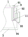
FIG. 3 is a structural diagram of a lifting mechanism of the novel power distribution cabinet of the present invention;
fig. 4 is the utility model relates to a novel power distribution cabinet's section view of overlooking.
In the figure: 1. an upper cabinet body; 101. a cabinet body; 102. a heat dissipation opening; 103. a plugboard; 2. a sliding plate; 3. a lower cabinet body; 4. a second rod body; 5. a first rod body; 6. a first door panel; 7. a second door panel; 8. a baffle plate; 9. a lifting mechanism; 91. rotating the block; 92. a screw rod; 93. a ball nut; 94. a box body; 10. a filter screen; 11. a connecting rod.
Detailed Description
In order to make the technical means, creation features, achievement purposes and functions of the present invention easy to understand, the present invention is further described below with reference to the following embodiments.
In the description of the present invention, it should be noted that the terms "upper", "lower", "inner", "outer", "front end", "rear end", "both ends", "one end", "the other end" and the like indicate orientations or positional relationships based on the orientations or positional relationships shown in the drawings, and are only for convenience of description and simplification of description, but do not indicate or imply that the device or element to which the reference is made must have a specific orientation, be constructed in a specific orientation, and be operated, and thus, should not be construed as limiting the present invention. Furthermore, the terms "first" and "second" are used for descriptive purposes only and are not to be construed as indicating or implying relative importance.
In the description of the present invention, it is to be noted that, unless otherwise explicitly specified or limited, the terms "mounted," "disposed," "connected," and the like are to be construed broadly, and for example, "connected" may be either fixedly connected or detachably connected, or integrally connected; can be mechanically or electrically connected; they may be connected directly or indirectly through intervening media, or they may be interconnected between two elements. The specific meaning of the above terms in the present invention can be understood in specific cases to those skilled in the art.
As shown in fig. 1-4, a novel power distribution cabinet, including the upper cabinet body 1, the below of the upper cabinet body 1 is equipped with lower cabinet body 3, the upper cabinet body 1 is pegged graft with lower cabinet body 3, the outer wall of the upper cabinet body 1 is fixed with sliding plate 2, the bottom embedding of sliding plate 2 has filter screen 10, the lower extreme and the lower cabinet body 3 sliding connection of sliding plate 2, be equipped with first body of rod 5 and second body of rod 4 about being present between the upper cabinet body 1 and the lower cabinet body 3, the lower extreme of first body of rod 5 is located the inner chamber of second body of rod 4, first body of rod 5 and upper cabinet body 1 fixed connection, second body of rod 4 and lower cabinet body 3 fixed connection, rotate respectively on first body of rod 5 and the second body of rod 4 and be equipped with first door plant 6 and second door plant 7, the lower extreme of first door plant 6 is located the inner chamber of second door plant 7, the inner chamber.
Go up cabinet body 1 and include cabinet body 101, heat dissipation opening 102 and plugboard 103, the fixed plugboard 103 that is equipped with of lower extreme of cabinet body 101, the lateral wall inner chamber of lower cabinet body 3 is equipped with the grafting chamber with plugboard 103 looks adaptation, all is equipped with heat dissipation opening 102 on the trilateral lateral wall of cabinet body 101, is equipped with heat dissipation opening 102 and plugboard 103, be convenient for dispel the heat and with lower cabinet body 3's grafting.
The lifting mechanism 9 comprises a rotating block 91, a screw 92, a ball nut 93 and a box body 94, an inner cavity of the box body 94 is rotatably provided with the screw 92, the upper end of the screw 92 penetrates through the upper end of the cabinet body 101 and extends to the lower end fixed connection above the upper end of the cabinet body and the rotating block 91, the ball nut 93 is sleeved on the screw 92 and is fixedly connected with the inner cavity side wall of the lower cabinet body 3 through a connecting rod 11, the inserting plate 103 of the upper cabinet body 1 can be enabled to slowly move out of the inserting cavity of the lower cabinet body 3, and the height of the cabinet body 101 can be conveniently adjusted.
Be fixed with baffle 8 on the right side wall of the lower cabinet body 3, be equipped with the joint piece with 8 joints of baffle on the second door plant 7, be convenient for fixed of door plant.
The cross section of joint piece is isosceles trapezoid structure, is equipped with on baffle 8 with the isosceles trapezoid joint chamber of joint piece looks adaptation and the inner chamber in joint chamber be fixed with the elastic extrusion pad for the door plant is fixed more firmly with baffle 8.
The inner cavity of the heat dissipation opening 102 communicates with the inner cavity of the slide plate 2 for facilitating heat dissipation.
It should be noted that the utility model relates to a novel power distribution cabinet, which is provided with a lifting mechanism 9, the lower cabinet body 3 is kept stationary, two sets of rotating blocks 91 are rotated simultaneously, the screw 92 is rotated, the upper cabinet body 1 is linearly moved up and down under the action of the ball nut 93, so that the inserting plate 103 moves in the inserting cavity of the lower cabinet body 3, the first rod body 5 moves in the inner cavity of the second rod body 4, the first door panel 6 moves in the inner cavity of the second door panel 7, and the sliding plate 2 moves on the outer side wall of the lower cabinet body 3 (the lower end of the sliding plate 2 is always in sliding connection with the side wall of the lower cabinet body 3), thereby realizing the change of the overall height of the power distribution cabinet, further changing the accommodating area inside the power distribution cabinet, increasing the application range of the power distribution cabinet, when not in use, the rotating blocks 91 can be reversely rotated, so that, the filter screen 10 is arranged, and the matching heat dissipation opening 102 can dissipate heat inside the power distribution cabinet and has a dustproof effect.
The basic principles and the main features of the invention and the advantages of the invention have been shown and described above. It will be understood by those skilled in the art that the present invention is not limited to the above embodiments, and that the foregoing embodiments and descriptions are provided only to illustrate the principles of the present invention without departing from the spirit and scope of the present invention. The scope of the invention is defined by the appended claims and equivalents thereof.
Claims (6)
1. The utility model provides a novel power distribution cabinet, includes the upper cabinet body (1), its characterized in that: a lower cabinet body (3) is arranged below the upper cabinet body (1), the upper cabinet body (1) is spliced with the lower cabinet body (3), a sliding plate (2) is fixed on the outer wall of the upper cabinet body (1), a filter screen (10) is embedded into the bottom of the sliding plate (2), the lower end of the sliding plate (2) is slidably connected with the lower cabinet body (3), a first rod body (5) and a second rod body (4) are arranged between the upper cabinet body (1) and the lower cabinet body (3) in an upper-lower mode, the lower end of the first rod body (5) is positioned in the inner cavity of the second rod body (4), the first rod body (5) is fixedly connected with the upper cabinet body (1), the second rod body (4) is fixedly connected with the lower cabinet body (3), a first door panel (6) and a second door panel (7) are respectively rotatably arranged on the first rod body (5) and the second rod body (4), and the lower end of the first door panel (6) is positioned in the inner cavity of the second door panel, the inner cavity of the upper cabinet body (1) is provided with lifting mechanisms (9) in bilateral symmetry.
2. The novel power distribution cabinet according to claim 1, characterized in that: go up cabinet body (1) including cabinet body (101), heat dissipation opening (102) and plugboard (103), the lower extreme of cabinet body (101) is fixed to be equipped with plugboard (103), the lateral wall inner chamber of lower cabinet body (3) is equipped with the grafting chamber with plugboard (103) looks adaptation, all be equipped with heat dissipation opening (102) on the trilateral lateral wall of cabinet body (101).
3. A new power distribution cabinet according to claim 1 or 2, characterized in that: lifting mechanism (9) include turning block (91), lead screw (92), ball nut (93) and box (94), the inner chamber of box (94) rotates and is equipped with lead screw (92), the upper end of the cabinet body (101) is run through and extend to the lower extreme fixed connection of its top and turning block (91) in the upper end of lead screw (92), ball nut (93) have been cup jointed on lead screw (92), ball nut (93) pass through connecting rod (11) and the inner chamber lateral wall fixed connection of the lower cabinet body (3).
4. The novel power distribution cabinet according to claim 1, characterized in that: the cabinet is characterized in that a baffle (8) is fixed on the right side wall of the lower cabinet body (3), and a clamping block clamped with the baffle (8) is arranged on the second door panel (7).
5. The novel power distribution cabinet according to claim 4, characterized in that: the cross section of joint piece is isosceles trapezoid structure, be equipped with on baffle (8) with the isosceles trapezoid joint chamber of joint piece looks adaptation and the inner chamber in joint chamber is fixed with the elastic extrusion pad.
6. The novel power distribution cabinet according to claim 2, characterized in that: the inner cavity of the heat dissipation opening (102) is communicated with the inner cavity of the sliding plate (2).
Priority Applications (1)
| Application Number | Priority Date | Filing Date | Title |
|---|---|---|---|
| CN201921444225.0U CN210723742U (en) | 2019-09-02 | 2019-09-02 | Novel power distribution cabinet |
Applications Claiming Priority (1)
| Application Number | Priority Date | Filing Date | Title |
|---|---|---|---|
| CN201921444225.0U CN210723742U (en) | 2019-09-02 | 2019-09-02 | Novel power distribution cabinet |
Publications (1)
| Publication Number | Publication Date |
|---|---|
| CN210723742U true CN210723742U (en) | 2020-06-09 |
Family
ID=70930117
Family Applications (1)
| Application Number | Title | Priority Date | Filing Date |
|---|---|---|---|
| CN201921444225.0U Active CN210723742U (en) | 2019-09-02 | 2019-09-02 | Novel power distribution cabinet |
Country Status (1)
| Country | Link |
|---|---|
| CN (1) | CN210723742U (en) |
-
2019
- 2019-09-02 CN CN201921444225.0U patent/CN210723742U/en active Active
Similar Documents
| Publication | Publication Date | Title |
|---|---|---|
| CN208299672U (en) | A kind of expandable type power supply subrack | |
| CN210723742U (en) | Novel power distribution cabinet | |
| CN210693078U (en) | Safe switch board convenient to dismouting | |
| CN112234466A (en) | Power box for municipal engineering | |
| CN216750733U (en) | Electric automatization controlling means | |
| CN211605782U (en) | Novel adjustable power distribution cabinet | |
| CN213151437U (en) | Power distribution cabinet | |
| CN214543239U (en) | Electrical automation electrical cabinet convenient to heat dissipation | |
| CN210897019U (en) | But remote control's high-voltage board divide-shut brake device | |
| CN209708871U (en) | A kind of safety protection structure of uncapping of hardware controller | |
| CN212649932U (en) | Module unit for electric appliance control | |
| CN211352727U (en) | Electric control equipment box | |
| CN212114361U (en) | Digital intelligent high-low voltage power distribution cabinet | |
| CN220273968U (en) | Dual-purpose panel switch | |
| CN216981190U (en) | Low-voltage electrical control cabinet with space adjusting function | |
| CN219203810U (en) | Combined control cabinet | |
| CN220570145U (en) | Automatic switch board of lock falls | |
| CN215579929U (en) | Outdoor control cabinet | |
| CN217115259U (en) | Switch board of firm installation | |
| CN214800264U (en) | Intelligent monitoring box with good heat dissipation performance | |
| CN212033535U (en) | Floor type distribution box | |
| CN220209695U (en) | Electric cabinet convenient for maintenance of motor train unit | |
| CN220798676U (en) | Electric power energy efficiency monitoring terminal | |
| CN219123625U (en) | Switch socket with multiple jacks | |
| CN111541160B (en) | High-voltage switch cabinet and use method thereof |
Legal Events
| Date | Code | Title | Description |
|---|---|---|---|
| GR01 | Patent grant | ||
| GR01 | Patent grant |