CN210709855U - Rolling crease-resistant structure of gravure press - Google Patents
Rolling crease-resistant structure of gravure press Download PDFInfo
- Publication number
- CN210709855U CN210709855U CN201920882228.6U CN201920882228U CN210709855U CN 210709855 U CN210709855 U CN 210709855U CN 201920882228 U CN201920882228 U CN 201920882228U CN 210709855 U CN210709855 U CN 210709855U
- Authority
- CN
- China
- Prior art keywords
- base
- bottom end
- rolling
- top end
- lead screw
- Prior art date
- Legal status (The legal status is an assumption and is not a legal conclusion. Google has not performed a legal analysis and makes no representation as to the accuracy of the status listed.)
- Active
Links
Images


Landscapes
- Rotary Presses (AREA)
Abstract
The utility model relates to the technical field of printing machines, in particular to a rolling crease-resistant structure of an intaglio printing machine, which reduces the occurrence of wrinkling of paper tapes, facilitates the disassembly of the rolled paper tapes and improves the practicability; the bottom end of the first base is connected with the left side of the top end of the bottom plate, and the bottom end of the first motor is connected with the left side of the top end of the first base; still include second base, riser, second pivot, second direction protection dish and first nut, the right-hand member of first pivot is provided with first direction protection dish, and inside the right-hand member of first direction protection dish stretched into to the sheathed tube left end of rolling, the bottom of second base was connected with the right side on bottom plate top, and the bottom of riser is connected with the top of second base, and the left end of riser is provided with first standing groove.
Description
Technical Field
The utility model relates to a field of printing machine especially relates to a gravure press's rolling crease-resistant structure.
Background
As is known, the winding structure of an intaglio printing press is an auxiliary device for winding, which is widely used in the field of printing presses; the crease-resistant structure of the existing gravure printing machine comprises a bottom plate, four groups of supporting legs, a first base, a first motor and a first speed reducer, wherein the left front side, the left rear side, the right front side and the right rear side of the bottom end of the bottom plate are respectively connected with the top ends of the four groups of supporting legs; when the winding structure of the existing gravure printing machine is used, firstly, a paper tape is sleeved on the outer side of the circumference of a winding sleeve, then, a first motor is started, and the first motor drives a first rotating shaft and the winding sleeve to wind through a first speed reducer; the rolling structure of the existing gravure printing machine is found in use, paper tapes are often wrinkled in the rolling process, the quality of finished products is affected, and the rolled paper tapes are difficult to disassemble, so that the practicability is poor.
Disclosure of Invention
In order to solve the technical problem, the utility model provides a reduce the emergence of the condition that the paper tape corrugates to the paper tape after making things convenient for the rolling is dismantled, improves the photogravure press's of practicality rolling crease-resistant structure.
The utility model discloses a rolling crease-resistance structure of gravure press, including bottom plate, four group's landing legs, first base, first motor, first speed reducer and rolling sleeve pipe, the left front side, the left rear side, the right front side and the right rear side of bottom plate bottom are connected with the top of four group's landing legs respectively, the bottom of first base is connected with the left side on bottom plate top, the bottom of first motor is connected with the left side on first base top, the bottom of first speed reducer is connected with the right side on first base top, the right part output of first motor is connected with the left part input of first speed reducer, the right part output of first speed reducer transversely is provided with first pivot; the rolling device also comprises a second base, a vertical plate, a second rotating shaft, a second guide protection disc and a first nut, wherein the right end of the first rotating shaft is provided with the first guide protection disc, the right end of the first guide protection disc extends into the left end of the rolling sleeve, the bottom end of the second base is connected with the right side of the top end of the bottom plate, the bottom end of the vertical plate is connected with the top end of the second base, the left end of the vertical plate is provided with a first placing groove, the right end of the vertical plate is provided with a second placing groove, a first bearing is arranged in the first placing groove, a second bearing is arranged in the second placing groove, inner rings of the first bearing and the second bearing are fixedly sleeved on the circumferential outer wall of the second rotating shaft, the left side of the circumferential outer wall of the second rotating shaft is provided with threads, the second guide protection disc is provided with a threaded hole which penetrates left and right, the left end of the second rotating shaft is inserted into and screwed into the right end of the threaded, the first nut is sleeved on the second rotating shaft in a threaded mode, and the left end of the first nut is tightly attached to the right end of the second guide protection disc.
The utility model discloses a rolling crease-resistance structure of gravure press still includes the roof, four groups of pillars, the third base, the second motor, the second speed reducer, reciprocating screw, two groups of connecting rods and slide rail, the left front side, the left rear side, the right front side and the right rear side of roof bottom are connected with the top of four groups of pillars respectively, the bottom of pillar is connected with the left front side, the left rear side, the right front side and the right rear side of bottom plate top respectively, the top of third base is connected with the right side of roof bottom, the top of second motor is connected with the right side of third base bottom, the top of second speed reducer is connected with the left side of third base bottom, the left output of second motor is connected with the right input of second speed reducer, the left output of second motor transversely is provided with first transmission shaft, the left end of first transmission shaft is connected with the right-hand member of reciprocating screw, reciprocating screw is provided with the reciprocating slider that matches with it, the bottom of reciprocal slider is provided with connecting device, and connecting device's bottom is provided with circular convex block, and the top of two sets of connecting rods is connected with the left side and the right side of roof bottom respectively, and the bottom of two sets of connecting rods is connected with the left side and the right side on slide rail top respectively, and the slidable is provided with the slider on the slide rail, and the bottom of slider is connected with the top of reciprocal slider.
The utility model discloses an intaglio press's rolling crease-resistant structure, connecting device includes the levogyration lead screw, screwed pipe and dextrorotation lead screw, the top of levogyration lead screw is connected with reciprocating slider's bottom, the first region of screwed pipe inside be provided with levogyration lead screw assorted screw thread, the inside second region of screwed pipe be provided with dextrorotation lead screw assorted screw thread, the bottom of levogyration lead screw is inserted and spiral shell dress to the top of screwed pipe inside, the top of dextrorotation lead screw is inserted and spiral shell dress to the bottom of screwed pipe inside, the bottom of dextrorotation lead screw is connected with circular convex block's top.
The utility model discloses an intaglio press's rolling crease-resistant structure still includes second nut and third nut, and second nut screw suit cover is established on the left-handed lead screw to the bottom of second nut pastes tightly with the top of screwed pipe, and third nut screw suit cover is established on the right-handed lead screw, and the top of third nut pastes tightly with the bottom of screwed pipe.
The utility model discloses an intaglio press's rolling crease-resistant structure still includes the bolt, and inside the bottom spiral shell dress of bolt inserted the top to the slider to the bottom of bolt was pasted tightly with the top of slide rail, and the top of bolt is provided with the butterfly handle.
The utility model discloses an intaglio press's rolling crease-resistant structure, the right-hand member of second pivot is provided with circular handle with one heart.
The utility model discloses an intaglio press's rolling crease-resistant structure still includes four group's threaded rods, and the bottom of four group's landing legs all is provided with the thread groove, and inside the top of four group's threaded rods inserted respectively and spiral shell dress to the bottom of four group's thread grooves, the bottom of four group's threaded rods all was provided with the cushion.
The utility model discloses an intaglio press's rolling crease-resistance structure still includes mounting panel and second transmission shaft, and the top of mounting panel is connected with the left side of roof bottom, and the right-hand member of mounting panel is provided with the fixed slot, and the inside of fixed slot is provided with the third bearing, and inside the inner circle of inserting and fixing to the third bearing the left end of second transmission shaft, the right-hand member of second transmission shaft and the left end of reciprocal lead screw were connected.
Compared with the prior art, the beneficial effects of the utility model are that: through the paper tape suit on the rolling sleeve pipe, place the rolling sleeve pipe between first direction expansion plate and second direction expansion plate, it presss from both sides tight fixedly to rotate second direction expansion plate messenger first direction expansion plate and second direction expansion plate to the rolling sleeve pipe, rotatory first nut to paste tightly and fix the position of second direction expansion plate for the second pivot with second direction expansion plate, first pivot of pivoted drives the rolling sleeve pipe through first direction expansion plate transmission and rotates, first direction expansion plate and second direction expansion plate lead to the paper tape, reduce the emergence of the condition that the paper tape corrugates, and conveniently dismantle the paper tape after rolling sleeve pipe and the rolling, improve the practicality.
Drawings
Fig. 1 is a schematic structural diagram of the present invention;
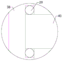
FIG. 2 is a partially enlarged view of the plane A in FIG. 1;
FIG. 3 is a schematic view of the structure of the connection of the reciprocating slider and the slider;
FIG. 4 is a partially enlarged view of the plane B in FIG. 1;
in the drawings, the reference numbers: 1. a base plate; 2. a support leg; 3. a first base; 4. a first motor; 5. a first speed reducer; 6. a first rotating shaft; 7. winding a sleeve; 8. a first guide protection disc; 9. a second base; 10. a vertical plate; 11. a first bearing; 12. a second bearing; 13. a second rotating shaft; 14. a second guide protection disc; 15. a first nut; 16. a top plate; 17. a pillar; 18. a third base; 19. a second motor; 20. a second speed reducer; 21. a first drive shaft; 22. a reciprocating screw; 23. a reciprocating slide block; 24. A circular bump; 25. a connecting rod; 26. a slide rail; 27. a slider; 28. a left-handed lead screw; 29. a solenoid; 30. a right-handed screw; 31. A second nut; 32. a third nut; 33. a bolt; 34. a butterfly handle; 35. a round handle; 36. a threaded rod; 37. cushion blocks; 38. mounting a plate; 39. a third bearing; 40. a second drive shaft.
Detailed Description
The following detailed description of the embodiments of the present invention is provided with reference to the accompanying drawings and examples. The following examples are intended to illustrate the invention, but are not intended to limit the scope of the invention.
As shown in fig. 1 to 4, the utility model discloses a rolling crease-resistant structure of gravure press, including bottom plate 1, four groups of landing legs 2, first base 3, first motor 4, first speed reducer 5 and rolling sleeve 7, the left front side, the left rear side, the right front side and the right rear side of bottom plate 1 bottom are connected with the top of four groups of landing legs 2 respectively, the bottom of first base 3 is connected with the left side of bottom plate 1 top, the bottom of first motor 4 is connected with the left side of first base 3 top, the bottom of first speed reducer 5 is connected with the right side of first base 3 top, the right part output of first motor 4 is connected with the left part input of first speed reducer 5, the right part output of first speed reducer 5 transversely is provided with first pivot 6; the winding device further comprises a second base 9, a vertical plate 10, a second rotating shaft 13, a second guiding protection disc 14 and a first nut 15, wherein the right end of the first rotating shaft 6 is provided with the first guiding protection disc 8, the right end of the first guiding protection disc 8 extends into the left end of the winding sleeve 7, the bottom end of the second base 9 is connected with the right side of the top end of the bottom plate 1, the bottom end of the vertical plate 10 is connected with the top end of the second base 9, the left end of the vertical plate 10 is provided with a first placing groove, the right end of the vertical plate 10 is provided with a second placing groove, the first placing groove is internally provided with a first bearing 11, the second placing groove is internally provided with a second bearing 12, inner rings of the first bearing 11 and the second bearing 12 are fixedly sleeved on the circumferential outer wall of the second rotating shaft 13, the left side of the circumferential outer wall of the second rotating shaft 13 is provided with threads, the second guiding protection disc 14 is provided with threaded holes which penetrate left and right, the left end, the left end of the second guide protection disc 14 extends into the right end of the winding sleeve 7, the first nut 15 is sleeved on the second rotating shaft 13 in a threaded mode, and the left end of the first nut 15 is tightly attached to the right end of the second guide protection disc 14; through the paper tape suit on the rolling sleeve pipe, place the rolling sleeve pipe between first direction expansion plate and second direction expansion plate, it presss from both sides tight fixedly to rotate second direction expansion plate messenger first direction expansion plate and second direction expansion plate to the rolling sleeve pipe, rotatory first nut to paste tightly and fix the position of second direction expansion plate for the second pivot with second direction expansion plate, first pivot of pivoted drives the rolling sleeve pipe through first direction expansion plate transmission and rotates, first direction expansion plate and second direction expansion plate lead to the paper tape, reduce the emergence of the condition that the paper tape corrugates, and conveniently dismantle the paper tape after rolling sleeve pipe and the rolling, improve the practicality.
The utility model discloses a rolling crease-resistance structure of gravure press still includes roof 16, four groups of pillars 17, third base 18, second motor 19, second speed reducer 20, reciprocal lead screw 22, two groups of connecting rods 25 and slide rail 26, the left front side, the left rear side, the right front side and the right rear side of roof 16 bottom are connected with the top of four groups of pillars 17 respectively, the bottom of pillar 17 is connected with the left front side, the left rear side, the right front side and the right rear side of bottom plate 1 top respectively, the top of third base 18 is connected with the right side of roof 16 bottom, the top of second motor 19 is connected with the right side of third base 18 bottom, the top of second speed reducer 20 is connected with the left side of third base 18 bottom, the left output of second motor 19 is connected with the right input of second speed reducer 20, the left output of second speed reducer 20 transversely is provided with first transmission shaft 21, the left end of first transmission shaft 21 is connected with the right-hand member of reciprocal lead screw 22, a reciprocating slide block 23 matched with the reciprocating screw rod 22 is arranged on the reciprocating screw rod 22, a connecting device is arranged at the bottom end of the reciprocating slide block 23, a round lug 24 is arranged at the bottom end of the connecting device, the top ends of two groups of connecting rods 25 are respectively connected with the left side and the right side of the bottom end of the top plate 16, the bottom ends of the two groups of connecting rods 25 are respectively connected with the left side and the right side of the top end of a slide rail 26, a slide block 27 is slidably arranged on the slide rail 26, and the bottom end of the slide; the circular arc bottom end of the circular convex block is in contact with the upper surface of the paper tape, the second motor is started, the second motor drives the first transmission shaft and the reciprocating screw rod to rotate through the second speed reducer, the reciprocating screw rod rotates to drive the reciprocating slide block and the slide block to do transverse reciprocating motion to flatten the paper tape below the slide block, the occurrence of wrinkling of the paper tape in the rolling process is reduced, and the practicability is improved.
The utility model discloses a rolling crease-resistance structure of gravure press, connecting device includes levogyration lead screw 28, screwed pipe 29 and dextrorotation lead screw 30, the top of levogyration lead screw 28 is connected with reciprocating slide 23's bottom, the first region of screwed pipe 29 inside is provided with the screw thread that matches with levogyration lead screw 28, the second region of screwed pipe 29 inside is provided with the screw thread that matches with dextrorotation lead screw 30, the bottom of levogyration lead screw 28 inserts and the spiral shell installs to the inside of the top of screwed pipe 29, the top of dextrorotation lead screw 30 inserts and the spiral shell installs to the inside of the bottom of screwed pipe 29, the bottom of dextrorotation lead screw 30 is connected with the top of circular lug 24; through rotating the solenoid, conveniently adjust the circular convex block for the distance between the rolling sleeve pipe, conveniently adjust the pressure between circular convex block and the paper tape, improve adaptability.
The utility model discloses a rolling crease-resistance structure of gravure press still includes second nut 31 and third nut 32, and second nut 31 spiral shell suit is established on levogyration lead screw 28 to the bottom of second nut 31 pastes tightly with the top of screwed pipe 29, and third nut 32 spiral shell suit is established on dextrorotation lead screw 30, and the top of third nut 32 pastes tightly with the bottom of screwed pipe 29; through rotating second nut and third nut respectively to pasting tightly with the solenoid, conveniently fix the distance between circular lug and the slider that reciprocates, improve stability.
The utility model discloses a rolling crease-resistance structure of gravure press still includes bolt 33, and the bottom spiral shell dress of bolt 33 inserts to the inside top of slider 27 to the bottom of bolt 33 pastes tightly with the top of slide rail 26, and the top of bolt 33 is provided with butterfly handle 34; through rotatory bolt to closely pasting with the slide rail, the position of fixed sliding block for the slide rail when the second motor is shut down is convenient, improves stability.
In the rolling crease-resistant structure of the gravure printing machine, the right end of the second rotating shaft 13 is concentrically provided with a circular handle 35; through the arrangement, a user can conveniently control the rotation of the second rotating shaft, and the convenience is improved.
The utility model discloses a rolling crease-resistance structure of gravure press still includes four groups of threaded rods 36, and the bottom of four groups of landing legs 2 all is provided with the thread groove, and the top of four groups of threaded rods 36 is inserted respectively and spiral shell dress to the inside bottom of four groups of thread grooves, and the bottom of four groups of threaded rods 36 all is provided with cushion 37; through rotating four group's threaded rods respectively, conveniently adjust wholly to stable, improve the practicality.
The utility model discloses a rolling crease-resistance structure of gravure press still includes mounting panel 38 and second transmission shaft 40, and the top of mounting panel 38 is connected with the left side of roof 16 bottom, and the right-hand member of mounting panel 38 is provided with the fixed slot, and the inside of fixed slot is provided with third bearing 39, and the left end of second transmission shaft 40 inserts and is fixed to the inner circle inside of third bearing 39, and the right-hand member of second transmission shaft 40 is connected with reciprocating screw 22's left end; through the arrangement, the left end supporting effect of the reciprocating screw rod is improved, and the stability is improved.
The utility model discloses a rolling crease-resistance structure of gravure press, it is at work, at first suit the paper tape in the circumference outside of rolling sleeve pipe, later place the rolling sleeve pipe between first direction protecting disc and second direction protecting disc, rotate second direction protecting disc and make first direction protecting disc and second direction protecting disc clamp tightly the rolling sleeve pipe fixedly, rotate first nut to paste closely and fix the position of second direction protecting disc relative to the second pivot with second direction protecting disc, the first pivot of rotation drives the rolling sleeve pipe through first direction protecting disc transmission and rotates, first direction protecting disc and second direction protecting disc guide the paper tape, reduce the emergence of the condition that the paper tape corrugates, and conveniently dismantle rolling sleeve pipe and the paper tape after the rolling, then with the circular convex block's circular arc bottom and the upper surface contact of paper tape, open the second motor, the second motor drives first transmission shaft and reciprocating screw through the second speed reducer and rotates, the reciprocating screw rotates to drive the reciprocating slide block and the slide block to do transverse reciprocating motion to flatten a paper tape below the slide block, then the first motor is started, and the first motor drives the first rotating shaft and the winding sleeve to wind through the first speed reducer.
The rolling crease-resistant structure of the gravure printing machine of the utility model adopts common mechanical modes as the installation mode, the connection mode or the setting mode, and can be implemented as long as the beneficial effects can be achieved; the utility model discloses a second motor of gravure press's rolling crease-resistance structure is purchase on the market, and this technical staff only need according to its subsidiary instructions install and operate can in the industry.
The foregoing is only a preferred embodiment of the present invention, and it should be noted that, for those skilled in the art, a plurality of modifications and variations can be made without departing from the technical principle of the present invention, and these modifications and variations should also be regarded as the protection scope of the present invention.
Claims (8)
1. A rolling crease-resistance structure of an intaglio printing machine comprises a bottom plate (1), four groups of supporting legs (2), a first base (3), a first motor (4), a first speed reducer (5) and a rolling sleeve (7), wherein the left front side, the left rear side, the right front side and the right rear side of the bottom end of the bottom plate (1) are respectively connected with the top ends of the four groups of supporting legs (2), the bottom end of the first base (3) is connected with the left side of the top end of the bottom plate (1), the bottom end of the first motor (4) is connected with the left side of the top end of the first base (3), the bottom end of the first speed reducer (5) is connected with the right side of the top end of the first base (3), the right output end of the first motor (4) is connected with the left input end of the first speed reducer (5), and the right output end of the first speed reducer (5) is transversely provided with; the device is characterized by further comprising a second base (9), a vertical plate (10), a second rotating shaft (13), a second guiding protection disc (14) and a first nut (15), wherein the right end of the first rotating shaft (6) is provided with a first guiding protection disc (8), the right end of the first guiding protection disc (8) extends into the left end of the rolling sleeve (7), the bottom end of the second base (9) is connected with the right side of the top end of the bottom plate (1), the bottom end of the vertical plate (10) is connected with the top end of the second base (9), the left end of the vertical plate (10) is provided with a first placing groove, the right end of the vertical plate (10) is provided with a second placing groove, a first bearing (11) is arranged in the first placing groove, a second bearing (12) is arranged in the second placing groove, inner rings of the first bearing (11) and the second bearing (12) are fixedly sleeved on the circumferential outer wall of the second rotating shaft (13), and threads are arranged on the left side of the circumferential outer wall of the second rotating, the screw hole that runs through about being provided with on second direction protection dish (14), the left end of second pivot (13) inserts and the spiral shell dress extremely inside the right-hand member of screw hole, the left end of second direction protection dish (14) stretches into to the right-hand member of rolling sleeve pipe (7) inside, and first nut (15) spiral shell dress cover is established on second pivot (13) to the left end of first nut (15) and the right-hand member of second direction protection dish (14) paste tightly.
2. The rolling crease-resistant structure of intaglio printing press as recited in claim 1, further comprising a top plate (16), four groups of pillars (17), a third base (18), a second motor (19), a second speed reducer (20), a reciprocating screw (22), two groups of connecting rods (25) and sliding rails (26), wherein the left front side, the left rear side, the right front side and the right rear side of the bottom end of the top plate (16) are respectively connected with the top ends of the four groups of pillars (17), the bottom ends of the pillars (17) are respectively connected with the left front side, the left rear side, the right front side and the right rear side of the top end of the bottom plate (1), the top end of the third base (18) is connected with the right side of the bottom end of the top plate (16), the top end of the second motor (19) is connected with the right side of the bottom end of the third base (18), the top end of the second speed reducer (20) is connected with the left side of the bottom end of the third base (18), the left output end of the second motor (19) is connected with, the left output end of the second speed reducer (20) is transversely provided with a first transmission shaft (21), the left end of the first transmission shaft (21) is connected with the right end of a reciprocating lead screw (22), a reciprocating slide block (23) matched with the reciprocating lead screw is arranged on the reciprocating lead screw (22), the bottom end of the reciprocating slide block (23) is provided with a connecting device, the bottom end of the connecting device is provided with a circular bump (24), the top ends of two groups of connecting rods (25) are respectively connected with the left side and the right side of the bottom end of a top plate (16), the bottom ends of the two groups of connecting rods (25) are respectively connected with the left side and the right side of the top end of a sliding rail (26), the sliding rail (26) is provided with a slide block (27) in a sliding manner.
3. The rolling crease-resistant structure of intaglio printing press as recited in claim 2, characterized in that the connecting means comprises a left-handed lead screw (28), a solenoid (29) and a right-handed lead screw (30), the top end of the left-handed lead screw (28) is connected with the bottom end of the reciprocating slider (23), the upper half area inside the solenoid (29) is provided with a thread matching with the left-handed lead screw (28), the lower half area inside the solenoid (29) is provided with a thread matching with the right-handed lead screw (30), the bottom end of the left-handed lead screw (28) is inserted and screwed into the top end inside the solenoid (29), the top end of the right-handed lead screw (30) is inserted and screwed into the bottom end inside the solenoid (29), and the bottom end of the right-handed lead screw (30) is connected with the top end of the circular bump (24).
4. The rolling crease-resistant structure of the intaglio printing press as recited in claim 3, further comprising a second nut (31) and a third nut (32), wherein the second nut (31) is screwed and sleeved on the left-handed screw (28), and the bottom end of the second nut (31) is tightly attached to the top end of the screw tube (29), the third nut (32) is screwed and sleeved on the right-handed screw (30), and the top end of the third nut (32) is tightly attached to the bottom end of the screw tube (29).
5. The rolling crease-resistant structure of intaglio printing press as recited in claim 4, further comprising a bolt (33), wherein the bottom end of the bolt (33) is inserted into the top end of the slider (27) in a threaded manner, and the bottom end of the bolt (33) is attached to the top end of the slide rail (26), and the top end of the bolt (33) is provided with a butterfly handle (34).
6. The rolling crease-resistant structure of intaglio printing press as recited in claim 5, characterized in that the right end of the second rotating shaft (13) is concentrically provided with a circular handle (35).
7. The rolling crease-resistant structure of the intaglio printing press as recited in claim 6, further comprising four sets of threaded rods (36), wherein the four sets of legs (2) are provided with threaded grooves at the bottom ends thereof, the four sets of threaded rods (36) are inserted and screwed into the four sets of threaded grooves at the top ends thereof, and the four sets of threaded rods (36) are provided with spacers (37) at the bottom ends thereof.
8. The rolling crease-resistant structure of intaglio printing press according to claim 7, further comprising a mounting plate (38) and a second transmission shaft (40), wherein the top end of the mounting plate (38) is connected with the left side of the bottom end of the top plate (16), the right end of the mounting plate (38) is provided with a fixing groove, the inside of the fixing groove is provided with a third bearing (39), the left end of the second transmission shaft (40) is inserted and fixed to the inside of the inner ring of the third bearing (39), and the right end of the second transmission shaft (40) is connected with the left end of the reciprocating screw (22).
Priority Applications (1)
| Application Number | Priority Date | Filing Date | Title |
|---|---|---|---|
| CN201920882228.6U CN210709855U (en) | 2019-06-13 | 2019-06-13 | Rolling crease-resistant structure of gravure press |
Applications Claiming Priority (1)
| Application Number | Priority Date | Filing Date | Title |
|---|---|---|---|
| CN201920882228.6U CN210709855U (en) | 2019-06-13 | 2019-06-13 | Rolling crease-resistant structure of gravure press |
Publications (1)
| Publication Number | Publication Date |
|---|---|
| CN210709855U true CN210709855U (en) | 2020-06-09 |
Family
ID=70961198
Family Applications (1)
| Application Number | Title | Priority Date | Filing Date |
|---|---|---|---|
| CN201920882228.6U Active CN210709855U (en) | 2019-06-13 | 2019-06-13 | Rolling crease-resistant structure of gravure press |
Country Status (1)
| Country | Link |
|---|---|
| CN (1) | CN210709855U (en) |
Cited By (2)
| Publication number | Priority date | Publication date | Assignee | Title |
|---|---|---|---|---|
| CN113086704A (en) * | 2021-03-30 | 2021-07-09 | 威海宝威新材料科技有限公司 | Be used for carbon fiber preimpregnation material to roll up device |
| CN116002429A (en) * | 2022-12-30 | 2023-04-25 | 江苏万邦特种纺织发展有限公司 | Automatic selvedge winding device for textile production |
-
2019
- 2019-06-13 CN CN201920882228.6U patent/CN210709855U/en active Active
Cited By (2)
| Publication number | Priority date | Publication date | Assignee | Title |
|---|---|---|---|---|
| CN113086704A (en) * | 2021-03-30 | 2021-07-09 | 威海宝威新材料科技有限公司 | Be used for carbon fiber preimpregnation material to roll up device |
| CN116002429A (en) * | 2022-12-30 | 2023-04-25 | 江苏万邦特种纺织发展有限公司 | Automatic selvedge winding device for textile production |
Similar Documents
| Publication | Publication Date | Title |
|---|---|---|
| CN206475090U (en) | Automobile chair frame fixture | |
| CN210709855U (en) | Rolling crease-resistant structure of gravure press | |
| CN108581778A (en) | A kind of steel pipe grinding device with waste recovery | |
| CN207086618U (en) | A kind of aluminium profiles sheet material high temperature bending press | |
| CN108049157A (en) | A kind of PLM clothes fabrication design Scissoring device | |
| CN205998716U (en) | Broad-adjustable wrap-up | |
| CN207592517U (en) | Tubing numerical control channelling machine | |
| CN211641690U (en) | Computer graphic drawing is with supplementary fixed bolster of external drawing | |
| CN205057547U (en) | A roller device for processing of large length and radius ratio work piece | |
| CN207057339U (en) | Veneer reeling machine | |
| CN207480800U (en) | A kind of bamboo product processing and positioning device | |
| CN216914023U (en) | Cutting device is used in rubber seal production | |
| CN109624491A (en) | A kind of garment printing device | |
| CN210080840U (en) | Supporting seat for intersecting line cutting machine | |
| CN208827210U (en) | Overturn turning mechanism and Paper handbag molding machine | |
| CN211588097U (en) | Roll-in forming device for welded pipe production line | |
| CN209009764U (en) | A kind of automatic Song Buji | |
| CN209407149U (en) | A kind of left and right is altogether to omnipotent all-electric CNC tube bending machine | |
| CN207448002U (en) | A kind of feeding supporting mechanism with bar positioning function on sawing machine | |
| CN206882671U (en) | A kind of cantilevered rolling device suitable for thin_wall cylinder part roll-in processing | |
| CN206203592U (en) | A kind of coil of strip supporting construction for sending volume machine | |
| CN217255644U (en) | Clamp for cold roll machining | |
| CN221192721U (en) | Textile fabric cutting device | |
| CN219032650U (en) | Multi-angle edge pressing device for synthetic leather processing | |
| CN219052464U (en) | Tube drawing machine with stable steel tube clamping |
Legal Events
| Date | Code | Title | Description |
|---|---|---|---|
| GR01 | Patent grant | ||
| GR01 | Patent grant |