CN210703305U - Rapid assembling and welding tool for device with screw hole - Google Patents
Rapid assembling and welding tool for device with screw hole Download PDFInfo
- Publication number
- CN210703305U CN210703305U CN201921359697.6U CN201921359697U CN210703305U CN 210703305 U CN210703305 U CN 210703305U CN 201921359697 U CN201921359697 U CN 201921359697U CN 210703305 U CN210703305 U CN 210703305U
- Authority
- CN
- China
- Prior art keywords
- bottom plate
- screw hole
- rectangular bottom
- rectangular
- pressing
- Prior art date
- Legal status (The legal status is an assumption and is not a legal conclusion. Google has not performed a legal analysis and makes no representation as to the accuracy of the status listed.)
- Active
Links
Images
Abstract
The utility model relates to a take quick dress of screw hole device to weld frock belongs to avionics and equips technical field. Comprises a rectangular top plate (1), a rectangular bottom plate (2), a positioning pin (3) and a pressing and buckling assembly; the utility model discloses the frock changes the dismouting mode of taking screw hole device in the past, and traditional printing board need use the screw to fix in advance, and is inefficient, and when the operation with take, causes the device damage easily, and the loss is huge. The utility model discloses the frock designs novel frock mode on not changing original production mode, can satisfy all kinds of quick dress that take screw hole device and weld and have enough to meet the need the protection, raises the efficiency, avoids damaging the risk.
Description
Technical Field
The utility model relates to a take quick dress of screw hole device to weld frock belongs to avionics and equips technical field.
Background
In the process of avionic assembly, a device with screw holes needs to be fixed on a printed board by screws in the process of assembling and welding, and then is dismounted after welding is finished. The efficiency is low, and the repeated operation, and the device screw demolishs the back, causes the damage because of colliding with easily in the turnover in-process, causes economic loss.
Disclosure of Invention
The utility model aims at providing a take quick dress of screw hole device to weld frock realizes that the brief summary of process does: through the use of frock, the cooperation of accessible locating pin and splint realizes taking screw hole device and quick fixed and the dismantlement of printing board, avoids colliding with damage, scrapping that the printing board transport appears in process of production simultaneously, practices thrift the cost.
The utility model discloses the technical scheme who takes does:
a rapid assembling and welding tool for a device with a screw hole is characterized by comprising a rectangular top plate 1, a rectangular bottom plate 2, a positioning pin 3 and a pressing and buckling assembly; the middle of the rectangular bottom plate 2 is provided with a square through hole, the edge of the rectangular bottom plate is provided with a fixed positioning pin 3, the pressing and buckling assembly is installed on the rectangular bottom plate 2, and the rectangular top plate 1 is fixed on the rectangular bottom plate 2 through the pressing and buckling assembly.
The pressing buckle component comprises a pressing buckle 4, a pressing buckle cap 5 and a spring 6; the spring 6 is sleeved on the press buckle cap 5 and is arranged at one end of the press buckle 4.
The middle of the rectangular top plate 1 is provided with a square through hole, and the edge of the square through hole is provided with an L-shaped groove.
And a circular observation hole is formed in the relative position of the positioning pin 3 on the rectangular top plate 1 and the rectangular bottom plate 2.
And U-shaped through holes are formed in the opposite positions of the pressing and buckling components on the rectangular top plate 1 and the rectangular bottom plate 2.
And circular grooves are formed in two sides of the U-shaped through hole of the rectangular top plate 1.
The edge of the square through hole of the rectangular bottom plate 2 is provided with an L-shaped groove, and four corners of the rectangular bottom plate 2 are provided with grooves and communicated with the L-shaped groove.
The pressing and buckling components are symmetrically arranged at four corners of the rectangular bottom plate 2.
The positioning pins 3 are fixed on two corresponding sides of the rectangular bottom plate 2.
The utility model has the advantages and beneficial effects:
the utility model discloses the frock changes the dismouting mode of taking screw hole device in the past, and traditional printing board need use the screw to fix in advance, and is inefficient, and when the operation with take, causes the device damage easily, and the loss is huge. The utility model discloses the frock designs novel frock mode on not changing original production mode, can satisfy all kinds of quick dress that take screw hole device and weld and have enough to meet the need the protection, raises the efficiency, avoids damaging the risk.
Drawings
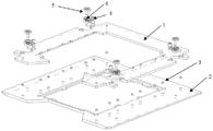
FIG. 1 is a schematic view of a device with screw holes for quick assembly and welding
Wherein: 1-rectangular top plate, 2-rectangular bottom plate, 3-positioning pin, 4-press buckle, 5-press buckle cap and 6-spring
Detailed Description
The present invention will be described in detail with reference to the accompanying drawings:
the quick assembly welding tool for the device with the screw hole comprises a rectangular top plate 1, a rectangular bottom plate 2, a positioning pin 3 and a pressing and buckling assembly; the middle of the rectangular bottom plate 2 is provided with a square through hole, the edge of the rectangular bottom plate is provided with a fixed positioning pin 3, the pressing and buckling assembly is installed on the rectangular bottom plate 2, and the rectangular top plate 1 is fixed on the rectangular bottom plate 2 through the pressing and buckling assembly.
The press buckle component comprises a press buckle 4, a press buckle cap 5 and a spring 6; the spring 6 is sleeved on the press buckle cap 5 and is arranged at one end of the press buckle 4; the pressing and buckling components are symmetrically arranged at four corners of the rectangular bottom plate 2; for fixing the rectangular top plate 1 on the rectangular bottom plate 2 in a balanced manner; the positioning pins 3 are fixed on two corresponding sides of the rectangular bottom plate 2; a device for positioning and fixing the screw holes; the middle part of the rectangular top plate 1 is provided with a square through hole, and the edge of the square through hole is provided with an L-shaped groove. The pressing and holding device is used for pressing and holding the printed board; a circular observation hole is formed in the relative position of the rectangular top plate 1 and the rectangular bottom plate 2 on the positioning pin 3 and used for observing the installation condition of devices on the positioning pin 3; a U-shaped through hole is formed in the opposite position of the pressing and buckling component on the rectangular top plate 1 and the rectangular bottom plate 2; the installation is convenient. Circular grooves are formed in two sides of the U-shaped through hole of the rectangular top plate 1; the fixing press buckle 4 slides off the rectangular top plate 1; the edge of the square through hole of the rectangular bottom plate 2 is provided with an L-shaped groove for supporting the printed board, and four corners of the rectangular bottom plate are provided with grooves and communicated with the L-shaped groove, so that the printed board can be conveniently taken out from the L-shaped groove.
A printed board is placed on a rectangular bottom plate 2, a rectangular top plate 1 is placed on the printed board, a device is placed on the printed board through a positioning pin 3, and the device and the printed board are fixed between the rectangular top plate 1 and the rectangular bottom plate 2 through a pressing buckle assembly, a pressing buckle 4, a pressing buckle cap 5 and a spring 6.
Claims (8)
1. A rapid assembling and welding tool for a device with a screw hole is characterized by comprising a rectangular top plate (1), a rectangular bottom plate (2), a positioning pin (3) and a pressing and buckling assembly; the middle of the rectangular bottom plate (2) is provided with a square through hole, the edge fixing positioning pin (3) is pressed and buckled on the rectangular bottom plate (2), and the rectangular top plate (1) is fixed on the rectangular bottom plate (2) through the pressing and buckling component.
2. The tool for quickly assembling and welding the device with the screw hole according to claim 1, wherein the pressing buckle component comprises a pressing buckle (4), a pressing buckle cap (5) and a spring (6); the spring (6) is sleeved on the press buckle cap (5) and is arranged at one end of the press buckle (4).
3. The tool for quickly assembling and welding the device with the screw hole according to claim 1, wherein a square through hole is formed in the middle of the rectangular top plate (1), and an L-shaped groove is formed in the edge of the square through hole.
4. The tool for quickly assembling and welding the device with the screw hole according to claim 1, wherein a circular observation hole is arranged at the position, opposite to the positioning pin (3) on the rectangular top plate (1) and the rectangular bottom plate (2).
5. The tool for quickly assembling and welding the device with the screw hole according to claim 1, wherein a U-shaped through hole is formed in the position, opposite to the pressing and buckling component on the rectangular top plate (1) and the rectangular bottom plate (2).
6. The tool for quickly assembling and welding the device with the screw hole according to claim 5, wherein circular grooves are formed on two sides of the U-shaped through hole of the rectangular top plate (1).
7. The tool for quickly assembling and welding the device with the screw hole according to claim 1, wherein the edge of the square through hole of the rectangular bottom plate (2) is provided with an L-shaped groove, and four corners of the rectangular bottom plate (2) are provided with grooves and communicated with the L-shaped groove.
8. The tool for quickly assembling and welding the device with the screw hole according to claim 1, wherein the pressing and buckling components are symmetrically arranged at four corners of the rectangular bottom plate (2).
Priority Applications (1)
| Application Number | Priority Date | Filing Date | Title |
|---|---|---|---|
| CN201921359697.6U CN210703305U (en) | 2019-08-20 | 2019-08-20 | Rapid assembling and welding tool for device with screw hole |
Applications Claiming Priority (1)
| Application Number | Priority Date | Filing Date | Title |
|---|---|---|---|
| CN201921359697.6U CN210703305U (en) | 2019-08-20 | 2019-08-20 | Rapid assembling and welding tool for device with screw hole |
Publications (1)
| Publication Number | Publication Date |
|---|---|
| CN210703305U true CN210703305U (en) | 2020-06-09 |
Family
ID=70960652
Family Applications (1)
| Application Number | Title | Priority Date | Filing Date |
|---|---|---|---|
| CN201921359697.6U Active CN210703305U (en) | 2019-08-20 | 2019-08-20 | Rapid assembling and welding tool for device with screw hole |
Country Status (1)
| Country | Link |
|---|---|
| CN (1) | CN210703305U (en) |
-
2019
- 2019-08-20 CN CN201921359697.6U patent/CN210703305U/en active Active
Similar Documents
| Publication | Publication Date | Title |
|---|---|---|
| CN203523163U (en) | FPC hot-pressing positioning jig | |
| CN203636485U (en) | Positioning mechanism for machining ultrathin workpieces | |
| CN210703305U (en) | Rapid assembling and welding tool for device with screw hole | |
| CN203902961U (en) | Trademark hold-down device | |
| US20200298434A1 (en) | Cutting device | |
| CN108908180A (en) | Fingerprint mould group disassembles tooling and fingerprint mould group disassembling method | |
| CN209955313U (en) | Quick many caves pad pasting tool | |
| CN104368715A (en) | Blank locating device for stamping die | |
| CN204851896U (en) | Paste tool that wheat was drawn | |
| CN212791647U (en) | General glue dispensing jig for improved mobile phone mainboard | |
| CN210364731U (en) | Positioning tool for large data processing machine case face frame label | |
| CN203151870U (en) | Work fixture for transporting flexible circuit board | |
| CN209830171U (en) | Pressure riveting die | |
| CN207408080U (en) | A kind of blank pressing frame device for filter element test | |
| CN206046864U (en) | A kind of Quick locating structure of the progressive die and board | |
| CN214873416U (en) | Product silk screen printing tool is worn to multi-functional intelligence | |
| CN210397358U (en) | Frame glue assembling jig on mobile terminal | |
| CN204014293U (en) | The bearing fixture of auxiliary printed circuit board processing | |
| CN204262699U (en) | Novel pressure assembling structure | |
| CN204305498U (en) | A kind of connector, housing and electronic equipment | |
| CN109980411A (en) | A kind of multi-way sliding plug | |
| CN102990390A (en) | High-precision aluminum piece milling and locating fixture | |
| CN104741442A (en) | Square ironware sheet punching die with detachable punching needles | |
| CN217453687U (en) | Assembly fixture for press fitting connector | |
| CN214257055U (en) | Inhale quick subsides of location and paste dress tool |
Legal Events
| Date | Code | Title | Description |
|---|---|---|---|
| GR01 | Patent grant | ||
| GR01 | Patent grant |