CN210703241U - Welding machine with dust removal structure - Google Patents
Welding machine with dust removal structure Download PDFInfo
- Publication number
- CN210703241U CN210703241U CN201921565415.8U CN201921565415U CN210703241U CN 210703241 U CN210703241 U CN 210703241U CN 201921565415 U CN201921565415 U CN 201921565415U CN 210703241 U CN210703241 U CN 210703241U
- Authority
- CN
- China
- Prior art keywords
- dust
- dust absorption
- cantilever
- fixed
- welder
- Prior art date
- Legal status (The legal status is an assumption and is not a legal conclusion. Google has not performed a legal analysis and makes no representation as to the accuracy of the status listed.)
- Active
Links
Images


Abstract
The utility model discloses a welding machine with dust removal structure belongs to dust remover technical field, and its technical scheme main points are, including base, stand, cantilever and welder, the stand is vertical to be fixed in on the base, and the cantilever sets up on the stand, and welder sets up in the one end of cantilever, be provided with the dust removal subassembly on the welder, the dust removal subassembly includes the suction hood, divides dust absorption pipe and dust absorption pipeline, the suction hood with divide the mutual intercommunication setting of dust absorption pipe, divide the dust absorption pipe with dust absorption pipeline intercommunication sets up, divides on dust absorption pipe box locates welder, all is provided with the tow chain on cantilever, stand and the base, is provided with the connecting piece between dust absorption pipeline and the tow chain to the dust absorption pipeline is fixed along the length direction of tow chain, and the end-to-end connection of dust absorption pipeline is provided with the dust remover. Therefore, clean gas can be discharged into the air, and the effect of purifying smoke generated by welding can be achieved. The utility model is suitable for a dust removal design of welding machine.
Description
Technical Field
The utility model belongs to the technical field of the dust remover technique and specifically relates to a welding machine with dust removal structure is related to.
Background
At present, a dust remover is a device for separating dust from flue gas, and is called a dust remover or a dust removing device. The performance of a precipitator is expressed in terms of the amount of gas that can be treated, the resistance loss of the gas as it passes through the precipitator, and the efficiency of the precipitation.
When the automatic welding machine is used for on-site welding work, a large amount of welding smoke is generated, and the smoke contains toxic metal oxides such as iron oxide, manganese oxide, fluoride and the like. Smoke dust and harmful gases have certain harm to the respiratory system, skin, eyes, blood and the like of a human body.
The prior technical scheme has the following defects: the dust removal device in the prior art mostly adopts a fixed dust collection mode, the welding gun head of the automatic welding machine is high in mobility, multi-angle welding is needed, and the fixed dust collection mode is difficult to effectively collect smoke dust and purify the smoke dust and then discharge the smoke dust.
SUMMERY OF THE UTILITY MODEL
The utility model aims at providing a welding machine with dust removal structure has the effect of purifying the smoke and dust.
The above technical purpose of the present invention can be achieved by the following technical solutions:
the utility model provides a welding machine with dust removal structure, includes base, stand, cantilever and welder, the stand is vertical to be fixed in on the base, the cantilever set up in on the stand, welder set up in the one end of cantilever, be provided with the dust removal subassembly on welder, the dust removal subassembly includes the suction hood, divides dust absorption pipe and dust absorption pipeline, the suction hood with divide the dust absorption pipe to communicate the setting each other, divide the dust absorption pipe with dust absorption pipeline intercommunication sets up, divide the dust absorption pipe box to locate on the welder, the cantilever the stand with all be provided with the tow chain on the base, the dust absorption pipeline with be provided with the connecting piece between the tow chain, and the dust absorption pipeline is followed the length direction of tow chain is fixed, the end-to-end connection of dust absorption pipeline is provided with the dust remover.
Through adopting above-mentioned technical scheme, welder can be the elevating movement on the stand, the stand can be along the length direction motion of base on the base, consequently welder can the welding of multi-angle, but welder is when carrying out the welding, produce easily and weld the cigarette, consequently set up inside the suction hood will weld the cigarette suction dust absorption pipeline that produces in the time of, then remove dust through the cigarette that welds that the dust remover will weld the production, thereby can be with in the clean gas outgoing to the air, thereby can play the effect of the smoke and dust that the purification welding produced.
The utility model discloses further set up to, the cantilever is close to welder's one end is provided with the spliced pole perpendicularly, welder is fixed in the spliced pole is kept away from the one end of cantilever, divide the dust absorption pipe to be close to the one end of spliced pole is provided with link and sealed end, the link with dust absorption pipeline fixed connection just communicates with each other the setting, the fixed cover of sealed end is located on the spliced pole.
Through adopting above-mentioned technical scheme, the link can play the effect of connecting branch dust absorption pipe and dust absorption pipeline, and the sealed end can play the fixed effect of dividing dust absorption pipe and spliced pole to further in order to fix the suction hood, thereby make the smoke and dust that the absorption welding that the suction hood can be better produced.
The utility model discloses further set up to, the seal groove of a plurality of "V" types is seted up to the sealed end, the seal groove court the direction of suction hood is seted up, be provided with the sealed arch of a plurality of "V" types on the spliced pole, it is a plurality of sealed arch and a plurality of the seal groove cooperation is connected, the cover is equipped with the sealing ring of "U" type on the sealed end outer wall, bolt fixed connection is passed through at the both ends of sealing ring.
Through adopting above-mentioned technical scheme, seal groove and sealed protruding cooperation are connected, can make to divide to be difficult to produce axial displacement between dust absorption pipe and the spliced pole to can make to divide the axial fixity between dust absorption pipe and the spliced pole inseparabler. Set up the sealing ring, can be with being connected between sealed end and the spliced pole inseparabler to can make branch dust absorption pipe be difficult to and spliced pole break away from.
The utility model discloses further set up to, adjacent two be formed with sealed piece between the seal groove, be equipped with sealed the pad on the inner wall of sealed piece.
Through adopting above-mentioned technical scheme, set up sealed the pad, can reduce the clearance between sealed end and the spliced pole, make the smoke and dust that the welding produced be difficult to follow the clearance discharge admission air between sealed end and the spliced pole.
The utility model discloses further set up to, the opening of suction hood sets up to the ellipse.
Through adopting above-mentioned technical scheme, set up the suction hood into the ellipse, the pressure that produces when can increase the dust absorption can get up the inside negative pressure gathering of suction hood, makes the dust absorption better.
The utility model discloses further set up to, the base the stand with all be provided with the tow chain standing groove on the cantilever, the tow chain is placed in the tow chain standing groove, the connecting piece includes fixed plate and a plurality of solid fixed ring, the fixed plate set up in one side of tow chain standing groove, it is a plurality of solid fixed ring is fixed in on the fixed plate, dust absorption pipeline places in the solid fixed ring.
Through adopting above-mentioned technical scheme, set up the tow chain standing groove and can be convenient for the tow chain on the one hand and place, on the other hand can be convenient for fixed to the fixed plate. The fixing ring is arranged, so that the dust collection pipe can be positioned.
The utility model discloses further set up to, fixed cover is equipped with a plurality of holding rings on the dust absorption pipeline, and is a plurality of the holding ring respectively with a plurality of solid fixed ring corresponds the setting, and is a plurality of be provided with first magnet on the holding ring, and is a plurality of gu be provided with second magnet on the fixed ring, first magnet with the cooperation of second magnet is connected.
Through adopting above-mentioned technical scheme, set up first magnet and second magnet, the location of dust absorption pipeline can be convenient for.
The utility model discloses further set up as, the dust remover is wet dust collector.
By adopting the technical scheme, because the smoke and dust is easy to generate during welding, the wet dust collector is arranged, the smoke and dust can be filtered by the wet dust collector firstly, and then clean gas is discharged into the air.
To sum up, the utility model discloses following beneficial effect has:
1. through the arrangement of the component assemblies, the effect of purifying smoke dust generated by welding can be achieved;
2. through the arrangement of the sealing groove, the sealing bulge and the sealing ring, the effect that the dust separating and collecting pipe is not easy to separate from the connecting column can be achieved;
3. through the setting of fixed plate, solid fixed ring, holding ring, first magnet and second magnet, can play the effect fixed with the location to dust absorption pipeline.
Drawings
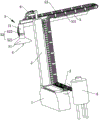
FIG. 1 is a schematic diagram of an overall structure according to one embodiment.
FIG. 2 is a schematic view of a dusting assembly according to an embodiment.
Fig. 3 is a partially enlarged schematic view of a portion a in fig. 1.
Fig. 4 is a partially enlarged schematic view of a portion B in fig. 2.
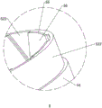
FIG. 5 is a schematic diagram of a connector according to one embodiment.
In the figure, 1, a base; 2. a column; 3. a cantilever; 31. connecting columns; 32. sealing the protrusion; 4. a welding gun; 5. a dust removal assembly; 51. a dust hood; 52. a dust collecting pipe is divided; 521. a connecting end; 522. sealing the end; 523. a sealing groove; 53. a dust collection duct; 531. a positioning ring; 532. a first magnet; 54. a seal ring; 55. a sealing block; 56. a gasket; 6. a drag chain; 61. a tow chain placing groove; 7. a connecting member; 71. a fixing plate; 72. a fixing ring; 73. a second magnet; 8. a dust remover.
Detailed Description
The present invention will be described in further detail with reference to the accompanying drawings.
Referring to fig. 1, the utility model discloses a welding machine with dust removal structure, including base 1, be provided with stand 2 in the one end of base 1. The upright column 2 can move along the length direction of the base 1, the cantilever 3 is arranged on the upright column 2, the cantilever 3 can move in the height direction of the upright column 2, and the cantilever 3 can also move transversely along the length direction of the cantilever. Be provided with welder 4 in the one end of cantilever 3, because cantilever 3 is fixed with stand 2, welder 4 is fixed with cantilever 3 again, therefore welder 4 can be on base 1 and be elevating movement, lateral shifting and longitudinal movement, therefore welder 4 can the welding of multi-angle. Since the welding torch 4 is likely to generate welding fumes during welding, the welding torch 4 is provided with the dust removing unit 5, and fumes generated during welding are treated by the dust removing unit 5 and then discharged into the atmosphere.
Referring to fig. 1 and 2, the dust removing assembly 5 includes a dust hood 51, a sub-dust suction pipe 52 and a dust suction duct 53, the dust hood 51 and the sub-dust suction pipe 52 are communicated with each other, the sub-dust suction pipe 52 and the dust hood 51 are fixed, and one end of the sub-dust suction pipe 52 away from the dust hood 51 is provided with two ports, namely a connection end 521 and a sealing end 522. The connecting end 521 of the sub-dust collection pipe 52 is fixedly connected and communicated with the dust collection pipeline 53, the sealing end 522 of the sub-dust collection pipe 52 is sleeved on the welding gun 4, and smoke generated during welding of the welding gun 4 can be sucked into the sub-dust collection pipe 52 through the dust collection cover 51.
Referring to fig. 3, tow chain placing grooves 61 are respectively arranged on the base 1, the upright column 2 and the cantilever 3, a tow chain 6 is placed in the tow chain placing grooves 61, the dust suction pipeline 53 is fixed along the length direction of the tow chain 6, a connecting piece 7 is arranged between the dust suction pipeline 53 and the tow chain 6, and a dust collector 8 (shown in fig. 1) is connected to the tail end of the dust suction pipeline 53, so that smoke is easily generated during welding, and the dust collector 8 is a wet dust collector, so that the smoke can be filtered by the wet dust collector firstly, and clean gas is discharged into the air. The welding fume generated during welding is sucked into the dust suction pipeline 53 through the dust suction cover 51, and then the welding fume generated during welding is dedusted through the deduster 8, so that clean gas can be discharged into the air, and the effect of purifying the fume generated during welding can be achieved. In order to improve the dust collection effect, the opening of the dust collection cover 51 is set to be oval, and the oval opening of the dust collection cover 51 is equivalent to the round opening of the dust collection cover 51, so that dust collection is concentrated, the pressure generated during dust collection can be increased, negative pressure in the dust collection cover 51 can be gathered, and the dust collection effect is better.
Referring to fig. 2 and 4, a connecting column 31 is vertically arranged at one end, close to a welding gun 4, of a cantilever 3, the welding gun 4 is fixed at one end, far away from the cantilever 3, of the connecting column 31, a sealing end 522 is fixedly sleeved on the connecting column 31, the connecting column 31 plays a role in fixing a branch dust suction pipe 52, the branch dust suction pipe 52 and a dust suction cover 51 can effectively suck smoke generated during welding, and therefore the smoke generated during welding can be reduced from entering air. In order to prevent the partial dust suction pipe 52 and the connecting column 31 from moving axially and to fix the partial dust suction pipe 52 and the connecting column 31 axially, a plurality of V-shaped sealing grooves 523 are formed in the sealing end 522, the sealing grooves 523 are formed in the direction towards the dust suction cover 51, a plurality of V-shaped sealing protrusions 32 are arranged on the connecting column 31, and the sealing protrusions 32 are connected with the sealing grooves 523 in a matched mode. The sealing block 55 is formed between the two adjacent sealing grooves 523, so that the connection between the connecting column 31 and the sealing end 522 is firmer and more reliable, and the flow of smoke generated during welding from the gap between the connecting column 31 and the sealing end 522 is reduced, therefore, the sealing gasket 56 is arranged on the inner wall of the sealing block 55, the gap between the sealing end 522 and the connecting column 31 can be reduced by the sealing gasket 56, and the smoke generated during welding is not easy to be discharged from the gap between the sealing end 522 and the connecting column 31 into the air. In order to enable the connection between the sealing end 522 and the connecting column 31 to be more tight, the outer wall of the sealing end 522 is sleeved with the U-shaped sealing ring 54, and two ends of the sealing ring 54 are fixedly connected through bolts, so that the dust separating and collecting pipe 52 is not easy to be disconnected from the connecting column 31.
Referring to fig. 3 and 5, the connecting member 7 includes a fixing plate 71 fixed to one side of the tow chain placing groove 61 and a plurality of fixing rings 72, the fixing rings 72 are fixed to the fixing plate 71, the fixing rings 72 are sleeved on the dust suction pipe 53, and the dust suction pipe 53 can be positioned by the fixing rings 72. In order to quickly position the dust suction pipe 53 to the fixing ring 72 after movement, a plurality of positioning rings 531 are fixedly sleeved on the dust suction pipe 53, the plurality of positioning rings 531 are respectively arranged corresponding to the plurality of fixing rings 72, first magnets 532 are arranged on the plurality of positioning rings 531, second magnets 73 are arranged on the plurality of fixing rings 72, and the first magnets 532 are connected with the second magnets 73 in a matching mode.
The implementation principle of the above embodiment is as follows: the welding gun 4 is easy to generate welding smoke when welding, the welding smoke generated during welding is sucked into the dust suction pipeline 53 through the dust suction cover 51, then the welding smoke generated during welding is removed through the dust remover 8, clean gas can be discharged into the air, and the effect of purifying the smoke generated during welding can be achieved. Since there is uncertainty about the specification of the article to be welded at the time of welding, the dust suction duct 53 needs to have mobility. When the dust suction pipeline 53 is static, the dust suction pipeline 53 is fixed in the fixing ring 72, when the dust suction pipeline 53 needs to be moved, the first magnet 532 and the second magnet 73 are disconnected, namely, the dust suction pipeline 53 and the fixing ring 72 are disconnected, and when the dust suction pipeline 53 is reset, the first magnet 532 and the second magnet 73 attract each other, namely, the dust suction pipeline 53 and the fixing ring 72 are connected.
The embodiment of this specific implementation mode is the preferred embodiment of the present invention, not limit according to this the utility model discloses a protection scope, so: all equivalent changes made according to the structure, shape and principle of the utility model are covered within the protection scope of the utility model.
Claims (8)
1. The utility model provides a welding machine with dust removal structure, includes base (1), stand (2), cantilever (3) and welder (4), stand (2) vertical be fixed in on base (1), cantilever (3) set up in on stand (2), welder (4) set up in the one end of cantilever (3), its characterized in that: be provided with dust removal subassembly (5) on welder (4), dust removal subassembly (5) include dust cage (51), divide dust absorption pipe (52) and dust absorption pipeline (53), dust cage (51) with divide dust absorption pipe (52) to communicate the setting each other, divide dust absorption pipe (52) with dust absorption pipeline (53) intercommunication sets up, divide dust absorption pipe (52) cover to locate on welder (4), cantilever (3) stand (2) with all be provided with tow chain (6) on base (1), dust absorption pipeline (53) with be provided with connecting piece (7) between tow chain (6), and dust absorption pipeline (53) are followed the length direction of tow chain (6) is fixed, the end-to-end connection of dust absorption pipeline (53) is provided with dust remover (8).
2. The welding machine with the dust removing structure as claimed in claim 1, wherein: cantilever (3) are close to the one end of welder (4) is provided with spliced pole (31) perpendicularly, welder (4) are fixed in spliced pole (31) is kept away from the one end of cantilever (3), divide dust absorption pipe (52) to be close to the one end of spliced pole (31) is provided with link (521) and sealed end (522), link (521) with dust absorption pipeline (53) fixed connection just communicates with each other the setting, sealed end (522) are fixed to be located on spliced pole (31).
3. The welding machine with the dust removing structure as claimed in claim 2, wherein: seal groove (523) of a plurality of "V" types are seted up to sealed end (522), seal groove (523) court the direction of suction hood (51) is seted up, be provided with sealed arch (32) of a plurality of "V" types on spliced pole (31), it is a plurality of sealed arch (32) and a plurality of seal groove (523) cooperation is connected, the cover is equipped with sealing ring (54) of "U" type on sealed end (522) outer wall, bolt fixed connection is passed through at the both ends of sealing ring (54).
4. A welding machine with dust removing structure according to claim 3, characterized in that: two adjacent seal grooves (523) are formed with seal blocks (55), and the inner wall of each seal block (55) is provided with a seal gasket (56).
5. A welding machine with dust removing structure according to claim 4, characterized in that: the opening of the dust hood (51) is oval.
6. The welding machine with the dust removing structure as claimed in claim 1, wherein: the base (1), stand (2) and all be provided with tow chain standing groove (61) on cantilever (3), tow chain (6) are placed in tow chain standing groove (61), connecting piece (7) are including fixed plate (71) and a plurality of solid fixed ring (72), fixed plate (71) set up in one side of tow chain standing groove (61), and a plurality of solid fixed ring (72) are fixed in on fixed plate (71), dust absorption pipeline (53) are placed in solid fixed ring (72).
7. The welding machine with the dust removing structure as claimed in claim 6, wherein: fixed cover is equipped with a plurality of holding rings (531) on dust absorption pipeline (53), and is a plurality of holding ring (531) respectively with a plurality of fixed ring (72) correspond the setting, and are a plurality of all be provided with first magnet (532) on holding ring (531), a plurality of all be provided with second magnet (73) on fixed ring (72), first magnet (532) with second magnet (73) cooperation is connected.
8. The welding machine with the dust removing structure as claimed in claim 7, wherein: the dust remover (8) is a wet dust remover.
Priority Applications (1)
| Application Number | Priority Date | Filing Date | Title |
|---|---|---|---|
| CN201921565415.8U CN210703241U (en) | 2019-09-19 | 2019-09-19 | Welding machine with dust removal structure |
Applications Claiming Priority (1)
| Application Number | Priority Date | Filing Date | Title |
|---|---|---|---|
| CN201921565415.8U CN210703241U (en) | 2019-09-19 | 2019-09-19 | Welding machine with dust removal structure |
Publications (1)
| Publication Number | Publication Date |
|---|---|
| CN210703241U true CN210703241U (en) | 2020-06-09 |
Family
ID=70961123
Family Applications (1)
| Application Number | Title | Priority Date | Filing Date |
|---|---|---|---|
| CN201921565415.8U Active CN210703241U (en) | 2019-09-19 | 2019-09-19 | Welding machine with dust removal structure |
Country Status (1)
| Country | Link |
|---|---|
| CN (1) | CN210703241U (en) |
Cited By (1)
| Publication number | Priority date | Publication date | Assignee | Title |
|---|---|---|---|---|
| CN114833497A (en) * | 2022-04-29 | 2022-08-02 | 河北卓锐科技有限公司 | Self-adaptive cantilever type shielded welding machine assembly |
-
2019
- 2019-09-19 CN CN201921565415.8U patent/CN210703241U/en active Active
Cited By (1)
| Publication number | Priority date | Publication date | Assignee | Title |
|---|---|---|---|---|
| CN114833497A (en) * | 2022-04-29 | 2022-08-02 | 河北卓锐科技有限公司 | Self-adaptive cantilever type shielded welding machine assembly |
Similar Documents
| Publication | Publication Date | Title |
|---|---|---|
| CN205587824U (en) | Dust extraction is welded in carbon dioxide gas protection | |
| CN208555460U (en) | A kind of synchronizing moving flue dust collecting processor for automatic welding machinery arm | |
| CN111822829A (en) | Robot welding smoke purifies collection device | |
| CN204565400U (en) | Electric welding unit dedusting toxin expelling device | |
| CN102527688B (en) | Fume welding and dust removing system for robot welding work station | |
| CN210703241U (en) | Welding machine with dust removal structure | |
| CN207431577U (en) | A kind of welding protective device | |
| CN205007797U (en) | Portable small -size welding fume clarifier | |
| CN105769438A (en) | Welding helmet with purification and filter function | |
| CN204504560U (en) | A kind of smoke abatement welder | |
| CN207839567U (en) | A kind of laser welding dust pelletizing system | |
| CN210231884U (en) | High-efficiency smoke purifying and filtering device with high negative pressure follow-up lower pumping drainage | |
| CN102847701A (en) | Manual welding smoke purifying device | |
| CN102824816A (en) | Smoke purification machine | |
| CN216325954U (en) | Welding device for machining steel beam and steel column of factory building | |
| CN201210000Y (en) | Door type mobile dust absorption cover | |
| CN210747205U (en) | Dust collector is selected separately to tobacco leaf | |
| CN214053033U (en) | Automatic following type smoke purification device | |
| CN207680280U (en) | A kind of environment-friendly high-efficiency weldering fume purifier | |
| CN107823994A (en) | A kind of environment-friendly high-efficiency welds fume purifier | |
| CN209576010U (en) | A kind of dusting smoke-discharging device for welding equipment | |
| CN215658366U (en) | Surfacing welding mechanical arm | |
| CN219188950U (en) | Auxiliary clamp for pipeline welding | |
| CN217701765U (en) | Dust collector for plasma cutting machine | |
| CN215352549U (en) | Welding fume dust collecting room body |
Legal Events
| Date | Code | Title | Description |
|---|---|---|---|
| GR01 | Patent grant | ||
| GR01 | Patent grant |