CN210699841U - Mixing equipment for polycarbonate modified material - Google Patents
Mixing equipment for polycarbonate modified material Download PDFInfo
- Publication number
- CN210699841U CN210699841U CN201920928769.8U CN201920928769U CN210699841U CN 210699841 U CN210699841 U CN 210699841U CN 201920928769 U CN201920928769 U CN 201920928769U CN 210699841 U CN210699841 U CN 210699841U
- Authority
- CN
- China
- Prior art keywords
- mixing
- compounding
- shaft
- gear
- bucket
- Prior art date
- Legal status (The legal status is an assumption and is not a legal conclusion. Google has not performed a legal analysis and makes no representation as to the accuracy of the status listed.)
- Active
Links
Images


Landscapes
- Processing And Handling Of Plastics And Other Materials For Molding In General (AREA)
- Mixers Of The Rotary Stirring Type (AREA)
Abstract
The utility model discloses a polycarbonate is compounding equipment for modified material, including the compounding box, compounding box inner chamber is equipped with compounding bucket, secondary compounding bucket once, compounding box inner chamber upper end is equipped with the compounding subassembly, the compounding subassembly comprises lead screw, sliding seat, first motor, first (mixing) shaft, first stirring vane, transmission shaft, first drive gear, driven gear and driving gear, the outer bottom middle part of secondary compounding bucket is equipped with the second motor, the vertical second (mixing) shaft that is equipped with of secondary compounding bucket inner middle side just second (mixing) shaft bottom tip with through coupling joint between the second motor output shaft, the cover has second stirring vane on the second (mixing) shaft.
Description
Technical Field
The utility model relates to a polycarbonate modified material production and processing field, concretely relates to compounding equipment for polycarbonate modified material.
Background
The polycarbonate modified material is usually required to be subjected to mixing and stirring operation of raw materials in the preparation process, the existing raw material mixing and stirring mode is single, a stirring rod is rotated by a motor through a stirring shaft so as to realize mixing, due to the fixed arrangement of the position of the motor, the working range of the stirring rod is limited due to the capacity, and sufficient, efficient and uniform mixing cannot be realized, the raw materials are usually directly discharged for subsequent processing after being subjected to primary mixing and stirring, the inside of the raw materials possibly has the existence of particles which are not sufficiently mixed after being subjected to primary stirring and mixing, the quality of the produced product is possibly poor due to the direct subsequent processing of the raw materials after being subjected to primary stirring and mixing, raw material particles are inevitably adhered to the end wall of the inner side of a mixing barrel in the mixing operation process, the adhesion of the raw material particles not only causes the waste of the raw materials but also reduces the cleanness inside, therefore, a mixing device for polycarbonate modified materials is needed.
Disclosure of Invention
In order to solve the problem, the utility model discloses a polycarbonate is compounding equipment for modified material, this equipment realize that abundant, high-efficient, the even stirring of raw materials mixes, realize that the secondary mixes the filtration of stirring back raw materials and derive, the quality of deriving the raw materials after the guarantee mixes, realizes the clearance of the inside end wall of mixing bucket, when reducing the raw materials extravagant, has also improved the inside cleanliness of equipment.
In order to achieve the above purpose, the utility model provides a following technical scheme: a mixing device for polycarbonate modified materials comprises a mixing box body, wherein a primary mixing barrel is arranged on the middle side of the upper end of an inner cavity of the mixing box body, a secondary mixing barrel is arranged in the mixing box body and is positioned below the primary mixing barrel, a mixing assembly is arranged at the upper end of the inner cavity of the mixing box body and consists of a screw rod arranged on the middle side of the upper end in the mixing box body, a sliding seat arranged at the lower end of the screw rod, a first motor arranged at the lower end of the sliding seat, a first mixing shaft with a vertically downward output shaft of the first motor connected through a coupling, a first mixing blade arranged on the first mixing shaft, a transmission shaft and a first transmission gear which are vertically arranged beside the primary mixing barrel in the mixing box body, a driven gear which is sleeved at the end part of the screw rod corresponding to the position of the transmission shaft, and a driving gear which is sleeved on the transmission shaft and corresponds to the position of the driven gear, the outer bottom middle part of secondary compounding bucket is equipped with the second motor, the vertical second (mixing) shaft that is equipped with in the inner medial side of secondary compounding bucket just second (mixing) shaft bottom tip with pass through the coupling joint between the second motor output shaft, the cover has second stirring vane on the second (mixing) shaft. The first motor, the second motor and the third motor are rotating motors, the driving gear and the driven gear are in meshing transmission with each other, and a material collecting bin is arranged at the bottom in the material mixing box body.
As an improvement of the utility model, a third motor is arranged on the outer side wall of the top end of the mixing box body, a driving belt wheel is sleeved on an output shaft of the third motor in the vertical upward direction, the end part of the top end of the transmission shaft movably penetrates through the inner side wall of the top end of the mixing box body, an extending end of the transmission shaft is sleeved with a driven belt wheel, a belt is sleeved between the driving belt wheel and the outer part of the driven belt wheel, the mixing box body is in a hollow cylindrical shape, a feeding hole is arranged on the inner side wall of the top part of the mixing box body, a feeding funnel is arranged beside the outer side of the top part of the mixing box body, the discharging end at the bottom of the feeding funnel is communicated with the feeding hole through a pipeline, a material guide pipeline is arranged in the mixing box body, the feeding end of the material guide pipeline is connected with the feeding hole, the discharging, an annular support frame is fixedly arranged on the middle side of the upper end of the fixing frame, an annular support groove is formed in the bottom end of the primary mixing barrel, the top of the annular support frame is positioned in the annular support groove, balls are uniformly and movably arranged at the top of the annular support frame in an equal radian manner, an annular rolling groove is formed in the outer end wall of the primary mixing barrel, positioning rollers are uniformly and movably arranged on the inner end wall of the mixing box body in a manner of corresponding to the equal radian of the position of the annular rolling groove, the positioning rollers are partially positioned in the annular rolling groove, first tooth grooves are uniformly formed in the outer end wall of the primary mixing barrel in a manner of corresponding to the equal radian of the position of the first transmission gear, the driving gear and the driven gear are bevel gears and are in meshing transmission with each other, positioning guide rails are parallelly arranged beside the side of the screw rod position at intervals, and positioning guide, the screw rod outside with be equipped with coupling assembling between the sliding seat upper end, the even vertical supplementary flitch that mixes of radian such as a compounding bucket medial extremity hugs closely the vertical first scraper blade that is equipped with in the inboard end wall position of a compounding bucket just first scraper blade top end pass through the link with the inboard end wall of compounding box is connected. The outside teeth of a cogwheel of first drive gear and first tooth's socket intermeshing, but a compounding bucket free rotation, ring support frame realizes the support of a compounding bucket, the location that the position of compounding bucket position was once realized to the positioning roller is firm, the rotation of lead screw is realized the sliding seat through coupling assembling and is followed lead screw length direction back and forth movement, coupling assembling adopts current screw drive principle technical design, be close to each other between supplementary flitch and the inboard end wall of a compounding bucket and leave the gap space, the motion range of sliding seat makes first stirring vane and supplementary flitch not influence each other, do not influence each other between supplementary flitch and the first scraper blade of mixing.
As an improvement of the utility model, the secondary mixing barrel comprises an upper disc-shaped frame body, a lower disc-shaped frame body and a cylindrical filtering frame arranged between the upper disc-shaped frame body and the lower disc-shaped frame body, wherein filtering holes are uniformly and densely formed on the cylindrical filtering frame, an annular chute is formed at the upper end of the upper disc-shaped frame body, an annular slide block is movably arranged in the annular chute, a vertical frame body is uniformly arranged between the upper end of the annular slide block and the lower end of the fixing frame, a circular discharging opening is formed in the middle of the bottom end of the primary mixing barrel, a material guide barrel is vertically and downwards connected with the circular discharging opening, a circular material guide opening is formed in the middle of the top end of the secondary mixing barrel, the lower end part of the material guide barrel movably penetrates through the inner cavity in the middle of the fixing frame and extends into the circular material guide opening, the inner of circular discharge opening is equipped with automatically controlled ooff valve, transmission shaft bottom end portion activity runs through the mount inner chamber stretches out downwards, the transmission shaft bottom stretches out the pot head and has second drive gear, second drive gear with vertical fixed round axle that is equipped with between the secondary compounding bucket outer end wall, on the round axle and correspond second drive gear position movable sleeve has transition gear, go up disc support body outside end wall isoplanar and evenly open and have the second tooth's socket, hug closely the vertical second scraper blade that is equipped with in cylindric filter frame outside end wall position just second scraper blade upper end tip with connect through the support body between the round axle bottom end portion. The second transmission gear is in meshing transmission with the transition gear, gear teeth outside the transition gear are in meshing transmission with the second gear groove, and the second scraper blade is used for cleaning the cylindrical filter rack.
Compared with the prior art, the utility model has the advantages of as follows: this equipment passes through the band pulley transmission, gear drive, the continuous change of stirring vane position is realized in the screw drive, realize the rotation of compounding bucket once, be equipped with supplementary material mixing plate, it is abundant to realize the raw materials, high efficiency, even stirring mixes, the clearance of the inboard end wall of compounding bucket is realized once to the first scraper blade that is equipped with, the secondary material mixing bucket that is equipped with realizes that the secondary raw materials mixes the stirring and filters and derives, the quality of deriving the raw materials after the guarantee mixes, realize the rotation of secondary material mixing bucket, supplementary raw materials stirring mixes the filtration and derives, the clearance that the second scraper blade that is equipped with realized the cylindric filter frame, also make the inside cleanliness of equipment improve when guaranteeing the cylindric filter frame and filtering the permeability.
Drawings
FIG. 1 is a schematic view of the overall structure of a mixing apparatus for polycarbonate modified materials according to the present invention;
FIG. 2 is a schematic view of the first motor position structure;
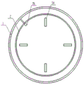
FIG. 3 is a schematic plan view of the transition gear position;
FIG. 4 is a schematic plan view of the first squeegee position;
list of reference numerals: 1. a mixing box body; 2. a primary mixing barrel; 3. a secondary mixing barrel; 4. a mixing assembly; 5. A screw rod; 6. a sliding seat; 7. a first motor; 8. a first stirring shaft; 9. a first stirring blade; 10. a drive shaft; 11. a first drive gear; 12. a driven gear; 13. a driving gear; 14. a second motor; 15. a second stirring shaft; 16. a second stirring blade; 17. a third motor; 18. a driving pulley; 19. a driven pulley; 20. a belt; 21. a feed hopper; 22. a fixed mount; 23. positioning the roller; 24. an auxiliary material mixing plate; 25. a first squeegee; 26. a second transmission gear; 27. a transition gear; 28. a second squeegee.
Detailed Description
Example 1: referring to fig. 1, 2, 3, 4, it is right now that the utility model provides a polycarbonate is compounding equipment for modified material explains, including compounding box 1, compounding box 1 inner chamber upper end medial side is equipped with once compounding bucket 2, just be located in compounding box 1 once compounding bucket 2 position medial side is equipped with secondary compounding bucket 3, compounding subassembly 4 is equipped with on compounding box 1 inner chamber, compounding subassembly 4 is by lead screw 5 that the medial side was equipped with in compounding box 1 top, slide bracket 6 that the lead screw 5 lower extreme was equipped with, first motor 7 that the slide bracket 6 lower extreme was equipped with, the first (mixing) shaft 8 that the vertical decurrent output shaft of first motor 7 passes through coupling joint, the first stirring vane 9 that is equipped with on first (mixing) shaft 8 in compounding box 1 and be located the other transmission shaft 10 that is equipped with of compounding bucket 2 outside vertically, On the transmission shaft 10 and correspond 2 position cover's of first compounding bucket first drive gear 11, lead screw 5 correspond 10 position of transmission shaft one side end overlap some driven gear 12 and transmission shaft 10 on and correspond driven gear 12 position cover's driving gear 13 and constitute, 3 outer bottom end middle parts of secondary compounding bucket are equipped with second motor 14, 3 inner middle sides of secondary compounding bucket are vertical to be equipped with second (mixing) shaft 15 just second (mixing) shaft 15 bottom tip with pass through the coupling joint between the 14 output shafts of second motor, the cover has second stirring vane 16 on the second (mixing) shaft 15.
Example 2: referring to fig. 1, 2 and 4, it is right now that the utility model provides a pair of the utility model discloses a material mixing equipment for polycarbonate modified material explains, be equipped with the third motor 17 just on the lateral wall of compounding box 1 top the vertical ascending output shaft of third motor 17 goes up the cover has driving pulley 18, the activity of transmission shaft 10 top end runs through the wall of compounding box 1 interior top stretches out and its stretching end cover has driven pulley 19, driving pulley 18 with the cover has belt 20 between the driven pulley 19 outside, compounding box 1 is hollow cylinder shape, it has the feed inlet to open on the lateral wall of compounding box 1 interior top, the other feed hopper 21 that is equipped with in compounding box 1 top outside and feed hopper 21 bottom discharge end with be linked together through the pipeline between the feed inlet, be equipped with the guide pipeline in the compounding box 1, the guide pipeline feed end with the feed inlet is connected, The discharge end is positioned right above the inner side end position of the primary mixing barrel 2, a fixing frame 22 is arranged in the mixing box body 1 and positioned between the primary mixing barrel 2 and the secondary mixing barrel 3, an annular supporting frame is fixedly arranged at the middle side of the upper end of the fixing frame 22, an annular supporting groove is formed in the inner bottom end of the primary mixing barrel 2, the top of the annular supporting frame is positioned in the annular supporting groove, balls are uniformly and movably arranged at the top of the annular supporting frame in equal radian, an annular rolling groove is formed in the outer side end wall of the primary mixing barrel 2, a positioning roller 23 is uniformly and movably arranged on the inner side end wall of the mixing box body 1 in equal radian corresponding to the annular rolling groove position, the positioning roller 23 is locally positioned in the annular rolling groove, and a first tooth socket is uniformly arranged on the outer side end wall of the primary mixing barrel 2 in equal radian corresponding to the first transmission gear, the driving gear 13 with driven gear 12 is bevel gear and meshing transmission each other, 5 position sides of lead screw are equipped with the location guide rail at the parallel interval, 6 upper ends of sliding seat just correspond location guide rail position is opened there is the location guide slot, 5 outsides of lead screw with be equipped with coupling assembling between 6 upper ends of sliding seat, the even vertical supplementary flitch 24 that is equipped with of radian such as 2 medial extremes of compounding bucket once hugs closely 2 inboard end wall positions of compounding bucket are vertical be equipped with first scraper blade 25 just first scraper blade 25 top end pass through the link with the inboard end wall of compounding box 1 is connected.
Example 3: referring to fig. 1 and 3, the mixing device for polycarbonate modified materials provided by the present invention is now described, wherein the secondary mixing barrel 3 comprises an upper disc-shaped frame body, a lower disc-shaped frame body, and a cylindrical filter frame arranged between the upper disc-shaped frame body and the lower disc-shaped frame body, wherein the cylindrical filter frame is uniformly and densely provided with filter holes, the upper end of the upper disc-shaped frame body is provided with an annular chute, an annular slide block is movably arranged in the annular chute, a vertical frame body is uniformly arranged between the upper end of the annular slide block and the lower end of the fixing frame 22, the middle part of the bottom end of the primary mixing barrel 2 is provided with a circular discharge opening, the circular discharge opening is vertically and downwardly connected with a guide barrel, the middle part of the top end of the secondary mixing barrel 3 is provided with a circular guide opening, the lower end of the guide barrel movably penetrates through, the utility model discloses a cylindrical filter frame, including circular guide opening, guide cylinder, transmission shaft 10, transmission shaft 26, drive shaft 10, drive shaft 26, second drive gear 26 position movable sleeve has transition gear 27, the last radian of going up disc support body outside end wall is evenly opened has the second tooth's socket, hugs closely the vertical second scraper blade 28 that is equipped with in drum filter frame outside end wall position the upper end tip of second scraper blade 28 with connect through the support body between the end of circular shaft bottom.
The present invention can also combine at least one of the technical features described in embodiments 2 and 3 with embodiment 1 to form a new embodiment.
The working principle is as follows: the raw materials of the polycarbonate modified materials are put into the feeding hopper and then are led into the primary mixing barrel through the pipeline, the feeding hole and the material guide pipeline, the annular support frame is used for supporting the position of the primary mixing barrel, and the positioning rollers realize stable positioning of the primary mixing barrel. The function of third motor passes through driving pulley, the belt, driven pulley drives the transmission shaft and rotates, the rotation of transmission shaft drives the driving gear, first transmission gear, second transmission gear rotates, thereby the driving gear drives the lead screw with the driven gear meshing transmission and rotates, the rotation of lead screw makes the sliding seat along lead screw length direction reciprocating motion through coupling assembling, the function of first motor drives first (mixing) shaft and rotates, first stirring vane realizes the mixed stirring of raw materials in the compounding bucket once, the outside teeth of a cogwheel of first transmission gear can drive the rotation of compounding bucket once with the transmission of first tooth's socket meshing, the clearance of the inboard end wall of compounding bucket is realized once to first scraper blade that is equipped with, the supplementary inside raw materials of compounding bucket of compounding board once stirs. The raw materials after the first compounding pass through circular discharge opening, in the leading-in secondary compounding bucket of guide cylinder, second drive gear and transition gear meshing transmission, the outside teeth of a cogwheel of transition gear drives the rotation of secondary compounding bucket with second gear groove meshing transmission, the function of second motor drives the rotation of second (mixing) shaft, the inside raw materials secondary stirring of secondary compounding bucket is realized to second stirring vane and is mixed, the filtration of secondary compounding bucket interior raw materials is derived in the cylindric filter stand realization, the clearance of cylindric filter stand is realized to the second scraper blade that is equipped with.
The technical means disclosed by the scheme of the present invention is not limited to the technical means disclosed by the above embodiments, but also includes the technical scheme formed by the arbitrary combination of the above technical features. It should be noted that, for those skilled in the art, without departing from the principle of the present invention, several improvements and modifications can be made, and these improvements and modifications are also considered as the protection scope of the present invention.
Claims (3)
1. The utility model provides a polycarbonate is compounding equipment for modified material, includes compounding box (1), its characterized in that, compounding box (1) inner chamber upper end medial side is equipped with once compounding bucket (2), just be located in compounding box (1) one time compounding bucket (2) position below medial side is equipped with secondary compounding bucket (3), compounding box (1) inner chamber upper end is equipped with compounding subassembly (4), compounding subassembly (4) by lead screw (5) that the medial side was equipped with in compounding box (1) top, sliding seat (6) that lead screw (5) lower extreme was equipped with, first motor (7) that sliding seat (6) lower extreme were equipped with, first motor (7) vertical decurrent output shaft pass through first (mixing) shaft (8) of coupling joint, first stirring vane (9) that are equipped with on first (mixing) shaft (8), just be located in compounding box (1) one time compounding bucket (2) outside is other to be equipped with transmission shaft (10), On transmission shaft (10) and correspond one time on mixing bucket (2) position cover some first drive gear (11), lead screw (5) correspond drive gear (13) that transmission shaft (10) position one side end portion overlaps driven gear (12) and transmission shaft (10) and correspond driven gear (12) position cover and constitute, secondary mixing bucket (3) outer bottom end middle part is equipped with second motor (14), secondary mixing bucket (3) inner medial side is vertical be equipped with second (mixing) shaft (15) just second (mixing) shaft (15) bottom tip with pass through coupling joint between second motor (14) the output shaft, the cover has second stirring vane (16) on second (mixing) shaft (15).
2. The mixing device for the polycarbonate modified material, according to claim 1, characterized in that a third motor (17) is arranged on the outer side wall of the top end of the mixing box body (1), a driving pulley (18) is sleeved on an output shaft of the third motor (17) which is vertically upward, the end part of the top end of the transmission shaft (10) movably penetrates through the inner top end wall of the mixing box body (1) to extend out, a driven pulley (19) is sleeved on the extending end of the inner top end wall, a belt (20) is sleeved between the driving pulley (18) and the outside of the driven pulley (19), the mixing box body (1) is hollow cylindrical, a feeding port is arranged on the inner top side wall of the mixing box body (1), a feeding funnel (21) is arranged beside the outer side of the top of the mixing box body (1), the discharging end at the bottom of the feeding funnel (21) is communicated with the feeding port through a pipeline, and a material guiding, the feeding end of the material guide pipeline is connected with the feeding hole, the discharging end is positioned right above the inner side position of the primary mixing barrel (2), a fixing frame (22) is arranged in the mixing box body (1) and between the primary mixing barrel (2) and the secondary mixing barrel (3), an annular supporting frame is fixedly arranged on the middle side of the upper end of the fixing frame (22), an annular supporting groove is formed in the inner bottom end of the primary mixing barrel (2), the top of the annular supporting frame is positioned in the annular supporting groove, balls are uniformly and movably arranged at the top of the annular supporting frame in equal radian, an annular rolling groove is formed in the outer end wall of the primary mixing barrel (2), positioning rollers (23) are uniformly and movably arranged on the inner end wall of the mixing box body (1) in equal radian corresponding to the position of the annular rolling groove, and the positioning rollers (23) are partially positioned in the annular rolling groove, one time on the wall of compounding bucket (2) outside end and correspond radian such as first drive gear (11) position is evenly opened there is first tooth's socket, driving gear (13) with driven gear (12) are bevel gear and mesh transmission each other, the other interval parallel of lead screw (5) position side is equipped with the location guide rail, sliding seat (6) upper end and correspondence location guide rail position is opened there is the location guide slot, lead screw (5) outside with be equipped with coupling assembling between sliding seat (6) upper end, the even vertical supplementary flitch (24) that are equipped with of radian such as compounding bucket (2) medial extremity once hug closely the vertical first scraper blade (25) that is equipped with of one time compounding bucket (2) inboard end wall position first scraper blade (25) top end pass through the link with compounding box (1) inboard end wall connection.
3. The mixing device for polycarbonate modified materials as claimed in claim 2, wherein the secondary mixing barrel (3) comprises an upper disc-shaped frame body, a lower disc-shaped frame body and a cylindrical filtering frame arranged between the upper disc-shaped frame body and the lower disc-shaped frame body, wherein filtering holes are uniformly and densely formed in the cylindrical filtering frame, an annular chute is formed in the upper end of the upper disc-shaped frame body, an annular sliding block is movably arranged in the annular chute, a vertical frame body is uniformly arranged between the upper end of the annular sliding block and the lower end of the fixing frame (22), a circular discharge opening is formed in the middle of the bottom end of the primary mixing barrel (2), a guide barrel is vertically and downwardly connected with the circular discharge opening, a circular guide opening is formed in the middle of the top end of the secondary mixing barrel (3), the lower end of the guide barrel movably penetrates through the middle inner cavity of the fixing frame (22) and extends into the circular, a bearing is arranged between the end wall at the inner side of the circular material guide opening and the end wall at the outer side of the material guide barrel discharge end, an electric control switch valve is arranged at the inner end of the circular discharge opening, the end part of the bottom end of the transmission shaft (10) movably penetrates through the inner cavity of the fixed frame (22) and extends downwards, a second transmission gear (26) is sleeved at the extending end of the bottom of the transmission shaft (10), a round shaft is vertically and fixedly arranged between the second transmission gear (26) and the outer end wall of the secondary mixing barrel (3), a transition gear (27) is movably sleeved on the round shaft and corresponds to the position of the second transmission gear (26), go up disc support body outside end wall isoplanatic degree and evenly open and have the second tooth's socket, hug closely the cylindric filter frame outside end wall position is vertically equipped with second scraper blade (28) just second scraper blade (28) upper end tip with connect through the support body between the circle axle bottom tip.
Priority Applications (1)
| Application Number | Priority Date | Filing Date | Title |
|---|---|---|---|
| CN201920928769.8U CN210699841U (en) | 2019-06-20 | 2019-06-20 | Mixing equipment for polycarbonate modified material |
Applications Claiming Priority (1)
| Application Number | Priority Date | Filing Date | Title |
|---|---|---|---|
| CN201920928769.8U CN210699841U (en) | 2019-06-20 | 2019-06-20 | Mixing equipment for polycarbonate modified material |
Publications (1)
| Publication Number | Publication Date |
|---|---|
| CN210699841U true CN210699841U (en) | 2020-06-09 |
Family
ID=70956107
Family Applications (1)
| Application Number | Title | Priority Date | Filing Date |
|---|---|---|---|
| CN201920928769.8U Active CN210699841U (en) | 2019-06-20 | 2019-06-20 | Mixing equipment for polycarbonate modified material |
Country Status (1)
| Country | Link |
|---|---|
| CN (1) | CN210699841U (en) |
Cited By (1)
| Publication number | Priority date | Publication date | Assignee | Title |
|---|---|---|---|---|
| CN110252177A (en) * | 2019-06-20 | 2019-09-20 | 南京清研新材料研究院有限公司 | A kind of modification material of polycarbonate mixing equipment |
-
2019
- 2019-06-20 CN CN201920928769.8U patent/CN210699841U/en active Active
Cited By (1)
| Publication number | Priority date | Publication date | Assignee | Title |
|---|---|---|---|---|
| CN110252177A (en) * | 2019-06-20 | 2019-09-20 | 南京清研新材料研究院有限公司 | A kind of modification material of polycarbonate mixing equipment |
Similar Documents
| Publication | Publication Date | Title |
|---|---|---|
| CN210699841U (en) | Mixing equipment for polycarbonate modified material | |
| CN110252177A (en) | A kind of modification material of polycarbonate mixing equipment | |
| CN210410538U (en) | Pretreatment kettle for glass edge covering material production | |
| CN210305826U (en) | Energy-saving environment-friendly drilling machine | |
| CN209813026U (en) | High-pressure metering extrusion device for producing nano-carbon PE/PET composite fibers | |
| CN216728099U (en) | Circulation treatment device for cleaning papermaking waste residues | |
| CN215782848U (en) | Detachable and cleanable raw material blending tank for processing polyurethane resin | |
| CN113651131B (en) | Even doffer of fodder | |
| CN210410353U (en) | Production agitated vessel is used to coal slurry additive | |
| CN212312579U (en) | Injection molding device capable of preventing feeding blockage | |
| CN112076852B (en) | Secondary is oil press crushed aggregates device for crushed aggregates | |
| CN210308526U (en) | High-efficient compounding device of cable material production | |
| CN210097657U (en) | Neutralization kettle for producing hydroxypropyl methyl cellulose | |
| CN211159804U (en) | High-efficient finish allotment equipment | |
| CN207724731U (en) | A kind of injection molding machine hopper filter device of Automobile Plastic Parts production and processing | |
| CN113290784A (en) | Injection molding machine with screening function | |
| CN114013702B (en) | Four-head servo liquid filling machine with automatic material supplementing structure | |
| CN214020315U (en) | Agitating unit is used in cushion production and processing | |
| CN221207074U (en) | Tea-seed oil residue filters purifier | |
| CN220166440U (en) | Refiner for processing fabrics | |
| CN219850597U (en) | Fused magnesia screening plant | |
| CN221190793U (en) | Chemical industry safety feeding device | |
| CN221245980U (en) | Graded fine filtering device for processing agricultural and sideline products | |
| CN211800376U (en) | Stirring equipment for chemical industry | |
| CN217773457U (en) | Automatic clear mill base filter |
Legal Events
| Date | Code | Title | Description |
|---|---|---|---|
| GR01 | Patent grant | ||
| GR01 | Patent grant | ||
| TR01 | Transfer of patent right |
Effective date of registration: 20230831 Address after: Room 1104, Building D, No. 606, Ningliu Road, Jiangbei New District, Nanjing, Jiangsu Province, 210000 Patentee after: Nanjing Qingqi New Material Technology Co.,Ltd. Address before: 11 / F, building D, 606 ningliu Road, Jiangbei new district, Nanjing City, Jiangsu Province, 210000 Patentee before: NANJING QINGYAN NEW MATERIAL RESEARCH INSTITUTE Co.,Ltd. |
|
| TR01 | Transfer of patent right |