CN210695740U - Vacuum mixing stirrer for meat products - Google Patents
Vacuum mixing stirrer for meat products Download PDFInfo
- Publication number
- CN210695740U CN210695740U CN202020711840.XU CN202020711840U CN210695740U CN 210695740 U CN210695740 U CN 210695740U CN 202020711840 U CN202020711840 U CN 202020711840U CN 210695740 U CN210695740 U CN 210695740U
- Authority
- CN
- China
- Prior art keywords
- stirring
- bevel gear
- bin
- shaft
- gear
- Prior art date
- Legal status (The legal status is an assumption and is not a legal conclusion. Google has not performed a legal analysis and makes no representation as to the accuracy of the status listed.)
- Expired - Fee Related
Links
- 235000013622 meat product Nutrition 0.000 title claims abstract description 17
- 238000003756 stirring Methods 0.000 claims abstract description 163
- 230000005540 biological transmission Effects 0.000 claims abstract description 25
- 230000002457 bidirectional effect Effects 0.000 claims abstract description 17
- 239000000463 material Substances 0.000 claims description 59
- 238000007790 scraping Methods 0.000 claims description 11
- 238000004519 manufacturing process Methods 0.000 abstract description 5
- 230000009286 beneficial effect Effects 0.000 description 8
- 238000000034 method Methods 0.000 description 6
- 238000007599 discharging Methods 0.000 description 4
- 239000003638 chemical reducing agent Substances 0.000 description 3
- 239000002994 raw material Substances 0.000 description 3
- 238000013019 agitation Methods 0.000 description 2
- 230000000694 effects Effects 0.000 description 2
- 235000013372 meat Nutrition 0.000 description 2
- 235000013305 food Nutrition 0.000 description 1
- 238000010030 laminating Methods 0.000 description 1
- 238000005086 pumping Methods 0.000 description 1
- XLYOFNOQVPJJNP-UHFFFAOYSA-N water Substances O XLYOFNOQVPJJNP-UHFFFAOYSA-N 0.000 description 1
Images
Landscapes
- Mixers Of The Rotary Stirring Type (AREA)
Abstract
The utility model relates to a vacuum mixing and stirring machine for meat products, which comprises a machine body, wherein the machine body comprises a stirring bin and a power bin, two stirring shafts which are parallel to each other are arranged in the stirring bin, and stirring blades are fixedly arranged on the stirring shafts; both ends of the stirring shaft are rotatably connected with the stirring bin, and one end of the stirring shaft penetrates through the stirring bin and extends into the power bin; one end of the stirring shaft extending into the power bin is fixedly connected with a first gear, a second gear is meshed between the two first gears, and the center of the second gear is fixedly connected with a transmission shaft; the transmission shaft is provided with a bidirectional driving assembly, the bidirectional driving assembly comprises a driving motor used for driving the transmission shaft to rotate, and the driving motor is fixedly arranged in the power bin. The utility model discloses only need a driving motor, can realize the rotation of two (mixing) shafts, practiced thrift the electric energy, reduced manufacturing cost.
Description
Technical Field
The utility model belongs to the technical field of the technique of food processing equipment and specifically relates to a mixed mixer of meat products vacuum is related to.
Background
The meat product needs to undergo a plurality of processes in the processing process, wherein the processes include a stirring process, namely, various auxiliary materials and water are added into meat raw materials (such as meat paste) to be mixed, stirred and emulsified. Therefore, a mixing stirrer is needed in the mixing and stirring process of the meat product, and the vacuum mixing stirrer is a common device for mixing materials, so that the efficiency is high, and the operation is convenient.
The prior art can refer to the invention patent with application publication number CN104289120A, which discloses a vacuum double-shaft mixer, comprising a machine body, a feeding device installed on the machine body and a vacuum pumping device installed on the machine body, wherein the machine body comprises a power bin and a mixing bin, a material box cover is arranged at the upper end of the mixing bin, a discharge door is arranged at the lower part of the outer side wall of the mixing bin, two horizontal mixing devices which are parallel to each other are arranged in the mixing bin, a speed reducer connected with a mixing shaft and a motor connected with the speed reducer through a belt are arranged in the power bin, the feeding device comprises a shell fixed on the machine body, a feeding hydraulic cylinder arranged in the shell, a turning arm fixedly connected with an output shaft of the feeding hydraulic cylinder and a feeding fork rotatably connected with the turning arm, and a feeding piston cylinder rotatably connected with the feeding fork and the shell is.
The above prior art solutions have the following drawbacks: although the vacuum double-shaft stirrer can stir materials, each stirring device is provided with a respective motor which is driven by a belt and a speed reducer, so that two stirring shafts are required to be driven by two motors, electric energy is wasted, and the production cost is high.
SUMMERY OF THE UTILITY MODEL
Not enough to prior art exists, the utility model aims at providing a mixed mixer of meat products vacuum has the effect of practicing thrift electric energy, reduction in production cost and stirring.
The above utility model discloses an above-mentioned utility model purpose can realize through following technical scheme:
a vacuum mixing stirrer for meat products comprises a machine body, wherein the machine body comprises a stirring bin and a power bin, two stirring shafts which are parallel to each other are arranged in the stirring bin, and stirring blades are fixedly arranged on the stirring shafts; both ends of the stirring shaft are rotatably connected with the stirring bin, and one end of the stirring shaft penetrates through the stirring bin and extends into the power bin; one end of the stirring shaft extending into the power bin is fixedly connected with a first gear, a second gear is meshed between the two first gears, and the center of the second gear is fixedly connected with a transmission shaft; the transmission shaft is provided with a bidirectional driving assembly, the bidirectional driving assembly comprises a driving motor used for driving the transmission shaft to rotate, and the driving motor is fixedly arranged in the power bin.
The beneficial effect through adopting above-mentioned technical scheme is: the driving motor is started, the driving motor drives the second gear to rotate reversely and alternately, and the second gear drives the first gear to rotate reversely and alternately, so that the stirring shafts rotate reversely and alternately, and finally the stirring blades rotate reversely and alternately; and bidirectional drive subassembly can drive stirring vane and carry out reverse rotation in turn, makes material and stirring vane continuously be in relative motion's state to carry out intensive mixing to the material, promote the degree of consistency of material, improve the efficiency that the material mixes.
Further: the bidirectional driving assembly further comprises a first bevel gear perpendicular to the second bevel gear, the first bevel gear is fixedly connected with an output shaft of the driving motor, a second bevel gear is perpendicularly arranged at one end of the first bevel gear and can be meshed with the first bevel gear, a third bevel gear is perpendicularly arranged at the other end of the first bevel gear and can be meshed with the third bevel gear, the second bevel gear and the third bevel gear are fixedly connected with the transmission shaft, and the first bevel gear is provided with gear teeth not larger than half.
The beneficial effect through adopting above-mentioned technical scheme is: starting a driving motor, wherein the driving motor drives a first bevel gear to rotate, and when the first bevel gear rotates to be meshed with a second bevel gear, the second bevel gear drives a transmission shaft to rotate in one direction, so that a stirring shaft is driven to rotate in the opposite direction; when the first bevel gear rotates to be meshed with the third bevel gear, the third bevel gear drives the transmission shaft to rotate in the opposite direction, so that the stirring shaft is driven to rotate in the opposite direction; under the prerequisite that driving motor need not just reversing, can realize the reverse rotation in turn of (mixing) shaft, finally realized that the (mixing) shaft drives stirring vane and carries out reverse rotation in turn, made material and stirring vane continuously be in relative motion's state to carry out intensive mixing to the material, promote the degree of consistency of material.
Further: the stirring blade is of a propeller type.
The beneficial effect through adopting above-mentioned technical scheme is: the stirring vane of propeller type can constantly roll, promote the material in the stirring storehouse to make the material more even by stirring, the stirring vane of propeller type can promote the ejection of compact to the material moreover, improves the efficiency of unloading.
Further: and the stirring blade is provided with a first through hole.
The beneficial effect through adopting above-mentioned technical scheme is: when the stirring blades rotate along with the stirring shaft, the materials can flow through the second through hole, the flowability of the materials is increased, the materials are prevented from doing regular circular motion along with the stirring blades, the rotating condition of the materials is reduced, and therefore the materials are stirred more uniformly.
Further: and the stirring shaft is provided with a stirring frame for stirring materials at the edge of the stirring bin.
The beneficial effect through adopting above-mentioned technical scheme is: the bidirectional driving component drives the stirring shaft to rotate, the stirring shaft drives the stirring frame to rotate, and the stirring frame can enable materials which are far away from the center of the stirring shaft in the stirring bin to be stirred to a certain degree, so that the stirring uniformity is improved.
Further: and a second through hole is formed in the stirring frame.
The beneficial effect through adopting above-mentioned technical scheme is: when the stirring frame rotates along with the stirring shaft, the material can flow through the second through hole in the stirring frame, and the flowability of the material is increased, so that the material far away from the center of the stirring shaft can be stirred sufficiently, and the material is stirred more uniformly.
Further: and the stirring frame is fixedly provided with a scraping plate which is mutually attached to the inner wall of the stirring bin.
The beneficial effect through adopting above-mentioned technical scheme is: scrape the flitch and can rotate along stirring the storehouse inner wall along stirring the frame to scrape the material to the inner wall in stirring the storehouse, avoid the material adhesion on the inner wall in stirring the storehouse, and influence the degree of consistency of material.
Further: the scraping plate is inclined along the edge of the inner wall of the stirring bin.
The beneficial effect through adopting above-mentioned technical scheme is: the edge of scraping the flitch is the slope form and makes the material of stirring storehouse inner wall adhesion strike off by scraping the flitch more easily, and then promotes the degree of consistency of material.
To sum up, the utility model discloses a following at least one useful technological effect:
1. through the arrangement that the second gear is meshed between the two first gears and the transmission shaft is fixedly connected to the center of the second gear, the rotation of the two stirring shafts can be realized only by one driving motor, so that the electric energy is saved, and the production cost is reduced;
2. through the arrangement of the bidirectional driving assembly, the reverse alternate rotation of the stirring shaft can be realized on the premise that the driving motor does not need to rotate forward and backward, and finally, the reverse alternate rotation of the stirring blades is realized, so that the material and the stirring blades are continuously in a relative motion state, the material is fully stirred, the uniformity of the material is improved, and the material mixing efficiency is improved;
3. set firmly the setting of scraping the flitch with stirring storehouse inner wall laminating each other on the frame, can scrape the material to the inner wall in stirring storehouse, avoid the material adhesion on the inner wall in stirring storehouse, and influence the degree of consistency of material.
Drawings
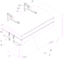
FIG. 1 is a schematic view of the overall structure of the embodiment;
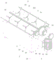
FIG. 2 is a schematic view showing the internal structure of the embodiment;
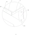
FIG. 3 is an enlarged partial schematic view of portion A of FIG. 2;
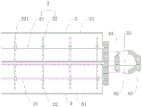
FIG. 4 is a schematic plan view highlighting the agitation device and the agitation frame.
In the figure, 1, a machine body; 11. a stirring bin; 111. a first support frame; 12. a power bin; 2. a stirring device; 21. a stirring shaft; 22. a stirring blade; 221. a first through hole; 3. a transmission device; 31. a first gear; 32. a second gear; 33. a drive shaft; 4. a bi-directional drive assembly; 41. a drive motor; 42. a first bevel gear; 43. a second bevel gear; 44. a third bevel gear; 5. a stirring frame; 51. a second through hole; 52. a scraping plate; 6. a box cover; 61. a second support frame; 7. a discharge door; 8. a hydraulic cylinder; 9. and a cylinder.
Detailed Description
The present invention will be described in further detail with reference to the accompanying drawings.
Referring to fig. 1 and 2, in order to disclose a vacuum mixing stirrer for meat products, the vacuum mixing stirrer comprises a machine body 1 and a vacuumizing device installed on the machine body 1, the machine body 1 comprises a stirring bin 11 and a power bin 12, the upper end of the stirring bin 11 is hinged with a box cover 6 for feeding, the lower part of one outer side wall of the stirring bin 11 is hinged with a discharge door 7, and the stirring device 2 is arranged inside the stirring bin 11; the power bin 12 is positioned at one end of the stirring bin 11 far away from the discharging door 7, and a transmission device 3 and a bidirectional driving assembly 4 for driving the stirring device 2 to rotate are arranged in the power bin 12. After an operator opens the box cover 6 and puts various raw materials into the stirring bin 11, the vacuumizing device is opened to vacuumize, the bidirectional driving assembly 4 is started to drive the transmission device 3 and the stirring device 2 to rotate, the stirring device 2 stirs the materials to fully mix the materials, and finally the materials are discharged from the discharge door 7 on the side wall of the stirring bin 11.
Referring to fig. 1, a first support frame 111 is arranged on one side of the stirring bin 11 perpendicular to the side wall provided with the discharge door 7, a second support frame 61 is arranged on the box cover 6, and one end of the second support frame 61 is hinged with the first support frame 111; articulated between support frame one 111 and the support frame two 61 have two parallel arrangement's pneumatic cylinder 8, and two pneumatic cylinder 8's base all is articulated with support frame one 111, and two pneumatic cylinder 8's piston rod all is articulated with support frame two 61. A piston rod of the hydraulic cylinder 8 contracts to drive the second support plate and the box cover 6 to rotate upwards along the hinged end, so that the box cover 6 is opened; and a piston rod of the hydraulic cylinder 8 extends to drive the second support plate and the box cover 6 to rotate downwards along the hinged end, so that the box cover 6 is closed.
Referring to fig. 2, the stirring device 2 includes two stirring shafts 21 that are parallel to each other and stirring vane 22 that sets firmly on stirring shaft 21, two stirring shafts 21 all with the mutual parallel arrangement in bottom of stirring storehouse 11, the both ends of every stirring shaft 21 all with stir storehouse 11 and rotate and be connected, and wherein one end passes stirring storehouse 11, and stretch into in the power storehouse 12 in proper order and be connected with transmission 3 and two-way drive assembly 4, two-way drive assembly 4 and transmission 3 can drive the rotation of (mixing) shaft 21, thereby it is rotatory to drive stirring vane 22, stir the material in the stirring storehouse 11.
Referring to fig. 2, the stirring blade 22 is of a propeller type, and can roll and lift the material continuously, improve the uniformity of stirring, and can push the material to discharge, and improve the discharging efficiency.
Referring to fig. 2 and 3, the first through hole 221 is formed in the stirring blade 22, and when the stirring blade 22 rotates along with the stirring shaft 21, the material can flow through the second through hole 51, so that the fluidity of the material is increased.
Referring to fig. 2, the transmission device 3 includes two first gears 31, a second gear 32 and a transmission shaft 33, the two first gears 31 are fixedly connected to the two stirring shafts 21, the second gear 32 is engaged between the two first gears 31, the transmission shaft 33 is fixedly connected to the center of the second gear 32, and the transmission shaft 33 is connected to the bidirectional driving assembly 4. Bidirectional drive assembly 4 drives second gear 32 and carries out reverse rotation in turn, and second gear 32 drives first gear 31 and carries out reverse rotation in turn to realize (mixing) shaft 21's reverse rotation in turn, finally realize stirring vane 22's reverse rotation in turn, only need a drive arrangement, can realize two (mixing) shaft 21's rotation, practiced thrift the electric energy, reduced manufacturing cost.
Referring to fig. 2, the bidirectional driving assembly 4 includes a driving motor 41, a first bevel gear 42, a second bevel gear 43 and a third bevel gear 44, the driving motor 41 is fixed inside the power bin 12, and an output shaft thereof is fixedly connected with the first bevel gear 42; the first bevel gear 42 and the second bevel gear 32 are perpendicular to each other, the second bevel gear 43 is perpendicular to the first bevel gear 42 and can be meshed at one end of the first bevel gear 42 away from the second bevel gear 32, the third bevel gear 44 is perpendicular to the first bevel gear 42 and can be meshed at one end of the first bevel gear 42 close to the second bevel gear 32, and the second bevel gear 43 and the third bevel gear 44 are fixedly connected with the transmission shaft 33; only one-half of the teeth are provided on the first bevel gear 42, and the diameter of the first bevel gear 42 is twice the diameter of the second bevel gear 43 and the third bevel gear 44. The driving motor 41 is started, and when the second bevel gear 43 and the third bevel gear 44 are respectively engaged with the first bevel gear 42, the rotation direction of the stirring shaft 21 is opposite, so that the stirring shaft 21 drives the stirring blades 22 to rotate in a reverse alternating manner, the materials and the stirring blades 22 are continuously in a relative motion state, and the stirring uniformity is ensured.
Referring to fig. 2 and 4, all being equipped with the stirring frame 5 that is used for stirring 11 edge materials in the stirring storehouse on two (mixing) shafts 21, two stirring frames 5 all are U type structure, leave the distance between two stirring frames 5, and stirring frame 5 can make and keep away from the material that (mixing) shaft 21 central point put in the stirring storehouse 11 and also can obtain the stirring to promote the homogeneity of stirring.
Referring to fig. 3, a second through hole 51 is formed in the stirring frame 5, and when the stirring frame 5 rotates, the material can flow through the second through hole 51, so that the fluidity of the material is increased, and the material far away from the center of the stirring shaft 21 is sufficiently stirred.
Referring to fig. 1 and 3, the lower portions of two side walls parallel to each other of the stirring bin 11 and the stirring shaft 21 are both in the shape of a quarter of a circular arc, and two stirring frames 5 are each fixedly provided with a scraping plate 52 attached to the circular arc inner wall of the stirring bin 11. The scraping plate 52 can scrape the inner wall of the stirring bin 11, so that the material is prevented from being adhered to the inner wall of the stirring bin 11 and the uniformity of the material is prevented from being influenced
Referring to fig. 3, the scraping plate 52 is inclined along the edge of the inner wall of the stirring bin 11, so that the material adhered to the inner wall of the stirring bin 11 can be more easily scraped, and the uniformity of the material can be further improved.
Referring to fig. 1, two discharge doors 7 are provided, and the upper ends of the two discharge doors 7 are respectively hinged to the bottom of the side wall of the stirring bin 11; an air cylinder 9 is hinged to a stirring bin 11 at the upper end of each discharge door 7, a base of the air cylinder 9 is hinged to the stirring bin 11, and a piston rod of the air cylinder 9 is hinged to the discharge door 7. A piston rod of the air cylinder 9 contracts to drive the discharge door 7 to rotate upwards along the hinged end, so that the discharge door 7 is opened; the piston rod of cylinder 9 extends, drives discharge door 7 and rotates downwards along the hinged end to realize closing of discharge door 7.
The implementation principle of the embodiment is as follows: when the vacuum mixing stirrer is used for mixing and stirring meat products, firstly, the hydraulic cylinder 8 is started to open the box cover 6, various raw materials are put into the stirring bin 11, and then the vacuumizing device is started for vacuumizing; then, starting the bidirectional driving component 4 to drive the transmission device 3 and the stirring device 2 to rotate, and stirring the materials by the stirring device 2 to fully mix the materials; and finally, starting the air cylinder 9 to open the discharge door 7, discharging the material from the discharge door 7, and finishing discharging.
The embodiment of this specific implementation mode is the preferred embodiment of the present invention, not limit according to this the utility model discloses a protection scope, so: all equivalent changes made according to the structure, shape and principle of the utility model are covered within the protection scope of the utility model.
Claims (7)
1. The utility model provides a meat products vacuum mixer, includes organism (1), organism (1) is including stirring storehouse (11) and power storehouse (12), be equipped with two (mixing) shaft (21) that are parallel to each other in stirring storehouse (11), stirring vane (22), its characterized in that have set firmly on (mixing) shaft (21): both ends of the stirring shaft (21) are rotatably connected with the stirring bin (11), and one end of the stirring shaft penetrates through the stirring bin (11) and extends into the power bin (12); one end of the stirring shaft (21) extending into the power bin (12) is fixedly connected with a first gear (31), a second gear (32) is meshed between the two first gears (31), and the center of the second gear (32) is fixedly connected with a transmission shaft (33); the transmission shaft (33) is provided with a bidirectional driving assembly (4), the bidirectional driving assembly (4) comprises a driving motor (41) for driving the transmission shaft (33) to rotate, and the driving motor (41) is fixedly arranged in the power bin (12); the bidirectional driving assembly (4) further comprises a first bevel gear (42) perpendicular to the second gear (32), the first bevel gear (42) is fixedly connected with an output shaft of the driving motor (41), one end of the first bevel gear (42) is vertically provided with a second bevel gear (43) and the first bevel gear and the second bevel gear can be meshed with each other, the other end of the first bevel gear (42) is vertically provided with a third bevel gear (44) and the third bevel gear can be meshed with each other, the second bevel gear (43) and the third bevel gear (44) are fixedly connected with the transmission shaft (33), and the first bevel gear (42) is provided with not more than one-half gear teeth.
2. The vacuum mixer for meat products as claimed in claim 1, wherein: the stirring blade (22) is of a propeller type.
3. The vacuum mixer for meat products as claimed in claim 1, wherein: and a first through hole (221) is formed in the stirring blade (22).
4. The vacuum mixer for meat products as claimed in claim 1, wherein: and a stirring frame (5) used for stirring materials at the edge of the stirring bin (11) is arranged on the stirring shaft (21).
5. The vacuum mixer for meat products as claimed in claim 4, wherein: and a second through hole (51) is formed in the stirring frame (5).
6. The vacuum mixer for meat products as claimed in claim 4, wherein: and a scraping plate (52) which is mutually attached to the inner wall of the stirring bin (11) is fixedly arranged on the stirring frame (5).
7. The vacuum mixer for meat products as claimed in claim 6, wherein: the scraping plate (52) is inclined along the edge of the inner wall of the stirring bin (11).
Priority Applications (1)
| Application Number | Priority Date | Filing Date | Title |
|---|---|---|---|
| CN202020711840.XU CN210695740U (en) | 2020-05-06 | 2020-05-06 | Vacuum mixing stirrer for meat products |
Applications Claiming Priority (1)
| Application Number | Priority Date | Filing Date | Title |
|---|---|---|---|
| CN202020711840.XU CN210695740U (en) | 2020-05-06 | 2020-05-06 | Vacuum mixing stirrer for meat products |
Publications (1)
| Publication Number | Publication Date |
|---|---|
| CN210695740U true CN210695740U (en) | 2020-06-09 |
Family
ID=70922712
Family Applications (1)
| Application Number | Title | Priority Date | Filing Date |
|---|---|---|---|
| CN202020711840.XU Expired - Fee Related CN210695740U (en) | 2020-05-06 | 2020-05-06 | Vacuum mixing stirrer for meat products |
Country Status (1)
| Country | Link |
|---|---|
| CN (1) | CN210695740U (en) |
Cited By (1)
| Publication number | Priority date | Publication date | Assignee | Title |
|---|---|---|---|---|
| CN115178135A (en) * | 2022-07-11 | 2022-10-14 | 黑龙江八一农垦大学 | Whole-course contactless automatic vacuum stuffing mixing equipment |
-
2020
- 2020-05-06 CN CN202020711840.XU patent/CN210695740U/en not_active Expired - Fee Related
Cited By (1)
| Publication number | Priority date | Publication date | Assignee | Title |
|---|---|---|---|---|
| CN115178135A (en) * | 2022-07-11 | 2022-10-14 | 黑龙江八一农垦大学 | Whole-course contactless automatic vacuum stuffing mixing equipment |
Similar Documents
| Publication | Publication Date | Title |
|---|---|---|
| CN212948438U (en) | Cement mixing plant for construction | |
| CN113019167A (en) | Medical treatment orthopedics gypsum raw materials agitating unit | |
| CN211185640U (en) | Auxiliary material unloading mechanism for processing line surface | |
| CN210695740U (en) | Vacuum mixing stirrer for meat products | |
| CN209076541U (en) | A kind of upright feed stuff agitator helping cutter with hydraulic drive type | |
| CN217573606U (en) | Kneading machine for producing fixed color masterbatch | |
| CN207428401U (en) | A kind of vacuum tumbler for food processing | |
| CN214598548U (en) | Material mixing device for refrigerator plate production | |
| CN213078109U (en) | Food mixer | |
| CN215550003U (en) | Production braided bag mix material processing equipment | |
| CN212445882U (en) | Internal mixer | |
| CN214210314U (en) | A raw materials mixing arrangement for chemical industry | |
| CN214871646U (en) | Road construction concrete mixing device | |
| CN214915213U (en) | Preserved szechuan pickle mixer | |
| CN213556682U (en) | Non-antibiotic feed additive mixer | |
| CN217527051U (en) | Lifting type one-way stirring vacuum emulsifying machine | |
| CN220835273U (en) | Raw material mixing equipment | |
| CN219984540U (en) | Mixing arrangement is used in waterproof coating production | |
| CN218221974U (en) | High strength gesso blender | |
| CN219482371U (en) | A compounding jar for producing leather auxiliary agent | |
| CN211487268U (en) | Safe and environment-friendly coating matching and preparing system | |
| CN219205693U (en) | Mixing arrangement is used in processing of bakery | |
| CN220835063U (en) | Mixing equipment for preparing raw and auxiliary materials of buckwheat biscuits | |
| CN217393653U (en) | Efficient sand mixer for continuous clay production | |
| CN219165549U (en) | Down-discharging dough mixer |
Legal Events
| Date | Code | Title | Description |
|---|---|---|---|
| GR01 | Patent grant | ||
| GR01 | Patent grant | ||
| CF01 | Termination of patent right due to non-payment of annual fee |
Granted publication date: 20200609 |
|
| CF01 | Termination of patent right due to non-payment of annual fee |