CN210695191U - Greenhouse ventilation structure - Google Patents
Greenhouse ventilation structure Download PDFInfo
- Publication number
- CN210695191U CN210695191U CN201921439244.4U CN201921439244U CN210695191U CN 210695191 U CN210695191 U CN 210695191U CN 201921439244 U CN201921439244 U CN 201921439244U CN 210695191 U CN210695191 U CN 210695191U
- Authority
- CN
- China
- Prior art keywords
- greenhouse
- stud
- ventilation structure
- sides
- ventilation
- Prior art date
- Legal status (The legal status is an assumption and is not a legal conclusion. Google has not performed a legal analysis and makes no representation as to the accuracy of the status listed.)
- Active
Links
Images

Classifications
-
- Y—GENERAL TAGGING OF NEW TECHNOLOGICAL DEVELOPMENTS; GENERAL TAGGING OF CROSS-SECTIONAL TECHNOLOGIES SPANNING OVER SEVERAL SECTIONS OF THE IPC; TECHNICAL SUBJECTS COVERED BY FORMER USPC CROSS-REFERENCE ART COLLECTIONS [XRACs] AND DIGESTS
- Y02—TECHNOLOGIES OR APPLICATIONS FOR MITIGATION OR ADAPTATION AGAINST CLIMATE CHANGE
- Y02A—TECHNOLOGIES FOR ADAPTATION TO CLIMATE CHANGE
- Y02A40/00—Adaptation technologies in agriculture, forestry, livestock or agroalimentary production
- Y02A40/10—Adaptation technologies in agriculture, forestry, livestock or agroalimentary production in agriculture
- Y02A40/25—Greenhouse technology, e.g. cooling systems therefor
Landscapes
- Greenhouses (AREA)
Abstract
The utility model discloses a greenhouse ventilation structure, which comprises a fixed seat and a framework, wherein the upper end of the fixed seat is butted and is provided with the framework, the framework comprises a vertical part at the bottom side and an arc-shaped part at the upper side, a cross beam is sleeved between the vertical parts, a fixed column is connected in the middle side of the cross beam in a penetrating way, the utility model drives a threaded sleeve sleeved on a stud to move upwards through a speed reducing motor, a left lighting plate and a right lighting plate at the upper end are turned outwards along a pin shaft under the driving of connecting rods at two sides to form a ventilation opening, a fan at two sides of the fixed column operates to assist in ventilation, the temperature condition at the inner side of the greenhouse is monitored by observing the numerical value on a temperature detector, the ventilation structure is more rapid and convenient, meanwhile, the damage to the membrane material at the outer side is avoided, when the ventilation is not needed, the speed reducing, the structural design is compact and reasonable, has strong practicability and is suitable for popularization.
Description
Technical Field
The utility model belongs to the technical field of warmhouse booth, concretely relates to warmhouse booth ventilation structure.
Background
The advent of greenhouses provides an excellent growing environment for some seasonal vegetables, thereby making it possible for them to appear on people's dining tables throughout the year. However, vegetables in the greenhouse are harsh to the growing environment, natural ventilation is the main mode of ventilation in south China, through reasonably setting a greenhouse windowing device, waste heat and residual moisture in the greenhouse can be discharged, and meanwhile, the content of indoor CO2 can be increased, so that the indoor environment meets the requirements of plant growth.
SUMMERY OF THE UTILITY MODEL
An object of the utility model is to provide a warmhouse booth ventilation structure to solve the problem that proposes among the above-mentioned background art.
In order to achieve the above object, the utility model provides a following technical scheme: a greenhouse ventilation structure comprises a fixed seat and a framework, wherein the upper end of the fixed seat is butted and provided with the framework, the framework comprises a vertical part at the bottom side and an arc-shaped part at the upper side, a cross beam is sleeved between the vertical parts, a fixed column is connected in a penetrating way at the middle side of the cross beam, a reinforcing rib is fixed at the upper end of the cross beam, a left lighting board and a right lighting board are respectively arranged at the upper ends of the arc-shaped parts at the two sides through pin shafts, the bottom sides of the left lighting board and the right lighting board are movably connected with a connecting rod through the pin shaft at the inner side of the connecting seat, the other end of the connecting rod is movably connected with a connecting seat at the side of a threaded sleeve, the threaded sleeve is sleeved on a stud, the stud is butted with a speed reducing motor at the bottom side through a coupler, the top end of the stud is butted, the sliding barrel is sleeved on a sliding column on the middle side, mounting frames are arranged on two sides of the fixing column at equal intervals, a mounting cavity is formed in the inner side of each mounting frame, and a fan is arranged in the inner side of each mounting cavity.
Preferably, the reinforcing ribs are two, the two reinforcing ribs are obliquely arranged, and a temperature detector is arranged on the side of each reinforcing rib.
Preferably, the bottom ends of the inner sides of the left and right lighting boards are provided with notches, the notches are attached to the sealing board at the bottom side, and the thickness of the cross section of each notch is consistent with that of the cross section of the sealing board.
Preferably, the height of the sliding cylinder is the same as that of the threaded sleeve, and the side of the sliding cylinder is movably connected with the left light board and the right light board through the connecting rod.
Preferably, the top ends of the sliding column and the stud are connected with the sealing plate in a butt joint mode, and the top ends of the sliding column and the stud are located on the same horizontal line.
Preferably, the diameters and the lengths of the cross sections of the stud and the stud are the same, and the speed reducing motor is fixedly connected with the cross beam through a screw.
The utility model discloses a technological effect and advantage: the utility model discloses a threaded sleeve rebound that cup joints on gear motor drives the double-screw bolt, the shuttle is along the synchronous rebound of shuttle under the drive of avris even post, the left daylighting board of upper end under the drive of both sides connecting rod, right daylighting board is turned along the round pin outside, form the vent, the fan operation of fixed column both sides is supplementary to be ventilated, numerical value on the thermometer is detected through surveing, monitor the temperature conditions of big-arch shelter inboard, more swift convenience, also avoid damaging the membrane material in the outside simultaneously, when not needing the ventilation, drive gear motor drives left daylighting board, right daylighting board resets can, structural design is closely reasonable, has very strong practicality, and is suitable for popularization.
Drawings
Fig. 1 is a schematic structural view of the present invention;
FIG. 2 is a schematic side view of the stud of the present invention;
fig. 3 is a schematic view of the top structure of the cross beam of the present invention.
In the figure: 1. a fixed seat; 2. a framework; 201. a vertical portion 202, an arc portion; 3. a cross beam; 4. reinforcing ribs; 5. a reduction motor; 6. a temperature detector; 7. a threaded sleeve; 8. a stud; 9. a connecting rod; 10. a shaft seat; 11. a right plane skylight; 12. a sealing plate; 13. a left daylighting panel; 14. a slide cylinder; 15. a traveler; 16. connecting the columns; 17. fixing a column; 18. a mounting frame; 19. a mounting cavity; 20. a fan.
Detailed Description
The technical solutions in the embodiments of the present invention will be described clearly and completely with reference to the accompanying drawings in the embodiments of the present invention, and it is obvious that the described embodiments are only some embodiments of the present invention, not all embodiments. Based on the embodiments in the present invention, all other embodiments obtained by a person skilled in the art without creative work belong to the protection scope of the present invention.
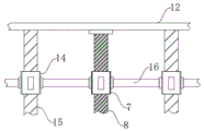
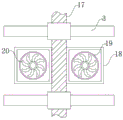
The utility model provides a greenhouse ventilation structure as shown in figures 1-3, which comprises a fixed seat 1 and a framework 2, wherein the framework 2 is arranged at the upper end of the fixed seat 1 in a butt joint mode, the framework 2 comprises a vertical part 201 at the bottom side and an arc part 202 at the upper side, a crossbeam 3 is sleeved between the vertical parts 201, a fixed column 17 is connected in the middle side of the crossbeam 3 in a penetrating mode, a reinforcing rib 4 is fixed at the upper end of the crossbeam 3, a left lighting board 13 and a right lighting board 11 are respectively arranged at the upper ends of the arc parts 202 at the two sides through a pin shaft, the bottom sides of the left lighting board 13 and the right lighting board 11 are movably connected with a connecting rod 9 through the pin shaft at the inner side of the connecting seat, the other end of the connecting rod 9 is movably connected with the connecting seat at the side of a threaded sleeve 7, the threaded sleeve 7 is sleeved on a stud 8, the stud 8, the top end of the stud 8 is in butt joint with the sealing plate 12 through the shaft seat 10, the left side and the right side of the threaded sleeve 7 are in butt joint with the sliding barrel 14 through the connecting column 16, the sliding barrel 14 is sleeved on the sliding column 15 on the middle side, mounting frames 18 are arranged on two sides of the fixing column 17 at equal intervals, a mounting cavity 19 is formed in the inner side of each mounting frame 18, and a fan 20 is arranged on the inner side of each mounting cavity 19.
Specifically, the reinforcing ribs 4 are two, and two the reinforcing ribs 4 are obliquely arranged, and the temperature detector 6 is arranged on the side of each reinforcing rib 4.
Specifically, the bottom ends of the inner sides of the left and right daylighting panels 13 and 11 are provided with openings, the openings are attached to the sealing plate 12 at the bottom side, and the thickness of the cross section of each opening is consistent with that of the cross section of the sealing plate 12.
Specifically, the height of the sliding cylinder 14 is the same as that of the threaded sleeve 7, and the side of the sliding cylinder 14 is movably connected with the left lighting board 13 and the right lighting board 11 through the connecting rod 9.
Specifically, the top ends of the sliding column 15 and the stud 8 are connected with the sealing plate 12 in a butt joint mode, and the top ends of the sliding column 15 and the stud 8 are located on the same horizontal line.
Specifically, the cross-sectional diameters of the stud 8 and the strut 15 are the same, the speed reduction motor 5 is fixedly connected with the cross beam 3 through screws, and the speed reduction motor 5 is provided with a plurality of motors which are arranged in a linkage mode.
When the utility model is used and needs to ventilate, the side door of the greenhouse is opened, the speed reducing motor 5 runs to drive the butted stud 8 to rotate, thereby the threaded sleeve 7 sleeved on the stud 8 moves upwards, the sliding cylinder 14 moves upwards synchronously along the sliding column 15 under the drive of the side connecting column 16, the left lighting board 13 and the right lighting board 11 at the upper end are turned outwards along the pin shaft under the drive of the connecting rods 9 at the two sides to form a ventilation opening, the fans 20 at the two sides of the fixed column 17 operate to assist in ventilation, and by observing the numerical value on the temperature detector 6, the temperature condition at the inner side of the greenhouse is monitored more quickly and conveniently, meanwhile, the damage to the membrane material at the outer side is avoided, when ventilation is not needed, the speed reduction motor 5 is driven to drive the left daylighting panel 13 and the right daylighting panel 11 to reset, the structural design is compact and reasonable, the practicability is high, and the ventilation device is suitable for popularization.
It should be noted that the specific models of the reduction motor 5, the fan 20 and the temperature detector 6 need to be calculated according to the specific specification of the setting, and the corresponding calculation mode belongs to the prior art in the field, and therefore, the details are not repeated.
The control method and the principle of the reduction motor 5, the fan 20 and the temperature detector 6 will be clear to those skilled in the art and will not be described in detail herein.
Finally, it should be noted that: although the present invention has been described in detail with reference to the foregoing embodiments, it will be apparent to those skilled in the art that modifications and variations can be made in the embodiments or in part of the technical features of the embodiments without departing from the spirit and the scope of the invention.
Claims (6)
1. The utility model provides a warmhouse booth ventilation structure, includes fixing base (1) and skeleton (2), its characterized in that: the upper end of the fixed seat (1) is butted and is singly provided with a framework (2), the framework (2) comprises vertical parts (201) at the bottom side and arc-shaped parts (202) at the upper side, cross beams (3) are sleeved between the vertical parts (201), fixing columns (17) are connected in a penetrating way at the middle side of each cross beam (3), reinforcing ribs (4) are fixed at the upper end of each cross beam (3), a left lighting plate (13) and a right lighting plate (11) are respectively arranged at the upper ends of the arc-shaped parts (202) at two sides through pin shafts, the bottom sides of the left lighting plate (13) and the right lighting plate (11) are movably connected with a connecting rod (9) through the pin shaft at the inner side of the connecting seat, the other end of the connecting rod (9) is movably connected with the connecting seat at the side of the threaded sleeve (7), the threaded sleeve (7) is sleeved on the stud (8), and the stud (8) is butted, the top of double-screw bolt (8) passes through axle bed (10) and links to each other with closing plate (12) butt joint, the left and right sides of screw sleeve (7) passes through even post (16) and links to each other with traveller (14) butt joint, traveller (14) cup joint on traveller (15) of medial side, mounting bracket (18) have been installed to the both sides equidistance of fixed column (17), installation cavity (19) have been seted up to mounting bracket (18) inboard, fan (20) have been installed to the inboard of installation cavity (19).
2. The ventilation structure of the greenhouse as claimed in claim 1, wherein: the reinforcing rib (4) are provided with two, and two the reinforcing rib (4) slope sets up, temperature detect meter (6) have been installed to the avris of reinforcing rib (4).
3. The ventilation structure of the greenhouse as claimed in claim 1, wherein: openings are formed in the bottom ends of the inner sides of the left light collecting plate (13) and the right light collecting plate (11), the openings are attached to the sealing plate (12) on the bottom side, and the thickness of the cross section of each opening is consistent with that of the cross section of the sealing plate (12).
4. The ventilation structure of the greenhouse as claimed in claim 1, wherein: the height of the sliding cylinder (14) is the same as that of the threaded sleeve (7), and the side of the sliding cylinder (14) is movably connected with the left daylighting panel (13) and the right daylighting panel (11) through the connecting rod (9).
5. The ventilation structure of the greenhouse as claimed in claim 1, wherein: the top ends of the sliding column (15) and the stud (8) are connected with the sealing plate (12) in a butt joint mode, and the top ends of the sliding column (15) and the stud (8) are located on the same horizontal line.
6. The ventilation structure of the greenhouse as claimed in claim 1, wherein: the cross sections of the stud (8) and the sliding column (15) are the same in diameter and length, and the speed reducing motor (5) is fixedly connected with the cross beam (3) through screws.
Priority Applications (1)
| Application Number | Priority Date | Filing Date | Title |
|---|---|---|---|
| CN201921439244.4U CN210695191U (en) | 2019-09-02 | 2019-09-02 | Greenhouse ventilation structure |
Applications Claiming Priority (1)
| Application Number | Priority Date | Filing Date | Title |
|---|---|---|---|
| CN201921439244.4U CN210695191U (en) | 2019-09-02 | 2019-09-02 | Greenhouse ventilation structure |
Publications (1)
| Publication Number | Publication Date |
|---|---|
| CN210695191U true CN210695191U (en) | 2020-06-09 |
Family
ID=70924751
Family Applications (1)
| Application Number | Title | Priority Date | Filing Date |
|---|---|---|---|
| CN201921439244.4U Active CN210695191U (en) | 2019-09-02 | 2019-09-02 | Greenhouse ventilation structure |
Country Status (1)
| Country | Link |
|---|---|
| CN (1) | CN210695191U (en) |
-
2019
- 2019-09-02 CN CN201921439244.4U patent/CN210695191U/en active Active
Similar Documents
| Publication | Publication Date | Title |
|---|---|---|
| CN201260321Y (en) | Sun-shading energy-saving type beam-connected greenhouse with completely opened roof | |
| EP1281314A2 (en) | Ventilation device for hothouse | |
| CN210695191U (en) | Greenhouse ventilation structure | |
| CN110268884A (en) | Full-open type wound membrane greenhouse | |
| CN112302382A (en) | Green building structure with rotary solar panel | |
| CN107494065A (en) | A kind of intelligent-type constant constant temperature and humidity device based on Internet of Things | |
| CN213904783U (en) | Outdoor wind-resistant rain-proof LED display screen | |
| CN206544550U (en) | detachable canopy | |
| CN211861253U (en) | Glass greenhouse roof with ridge continuous ventilation system | |
| CN203373915U (en) | Power-driven clerestory opening and closing device | |
| CN208280682U (en) | A kind of pickle production builder's temporary shed | |
| CN112542796A (en) | Heat-dissipation rainproof outdoor electric power cabinet | |
| CN220831012U (en) | Greenhouse structure for vegetable planting | |
| CN207269463U (en) | A kind of agricultural greenhouse arch tube attachment device | |
| CN206686754U (en) | Warmhouse booth equipment with slidingtype ventilating mechanisms | |
| CN217446026U (en) | Movable telescopic shed | |
| CN206760235U (en) | The greenhouse rolling blind of Automated condtrol | |
| CN111587718A (en) | Bilateral window-turning type top ventilation device of circular arch greenhouse | |
| CN219834947U (en) | Double-sawtooth greenhouse with rapid ventilation structure | |
| CN218977508U (en) | Top side ventilation structure for small-span film greenhouse | |
| CN220955388U (en) | Sunshade structure for wooden house | |
| CN216087910U (en) | Ventilation solar protection devices and warmhouse booth | |
| CN219474678U (en) | Environment monitoring device for intelligent building site | |
| CN219165271U (en) | Vegetable greenhouse with air-permeable skylight | |
| CN211143525U (en) | Rain-proof drainage stainless steel hood |
Legal Events
| Date | Code | Title | Description |
|---|---|---|---|
| GR01 | Patent grant | ||
| GR01 | Patent grant |