CN210683719U - Novel biomass pellet fuel granulating and forming machine - Google Patents
Novel biomass pellet fuel granulating and forming machine Download PDFInfo
- Publication number
- CN210683719U CN210683719U CN201921450604.0U CN201921450604U CN210683719U CN 210683719 U CN210683719 U CN 210683719U CN 201921450604 U CN201921450604 U CN 201921450604U CN 210683719 U CN210683719 U CN 210683719U
- Authority
- CN
- China
- Prior art keywords
- bin
- rollers
- forming machine
- pellet fuel
- mounting
- Prior art date
- Legal status (The legal status is an assumption and is not a legal conclusion. Google has not performed a legal analysis and makes no representation as to the accuracy of the status listed.)
- Expired - Fee Related
Links
Images

Classifications
-
- Y—GENERAL TAGGING OF NEW TECHNOLOGICAL DEVELOPMENTS; GENERAL TAGGING OF CROSS-SECTIONAL TECHNOLOGIES SPANNING OVER SEVERAL SECTIONS OF THE IPC; TECHNICAL SUBJECTS COVERED BY FORMER USPC CROSS-REFERENCE ART COLLECTIONS [XRACs] AND DIGESTS
- Y02—TECHNOLOGIES OR APPLICATIONS FOR MITIGATION OR ADAPTATION AGAINST CLIMATE CHANGE
- Y02E—REDUCTION OF GREENHOUSE GAS [GHG] EMISSIONS, RELATED TO ENERGY GENERATION, TRANSMISSION OR DISTRIBUTION
- Y02E50/00—Technologies for the production of fuel of non-fossil origin
- Y02E50/30—Fuel from waste, e.g. synthetic alcohol or diesel
Abstract
The utility model relates to a make-up machine technical field, concretely relates to novel living beings pellet fuel pelletization make-up machine, including storage silo, play feed bin, crushing storehouse, running roller, sharp piece, mounting panel, gear motor. The utility model has the advantages that: the point piece that sets up on two running rollers, the running roller is when synchronous antiport, the raw materials gets into between two running rollers, the breakage through point piece, the raw materials that makes the caking produces the breakage, the efficiency of sequent pelletization has been improved to at least a certain extent, workman's intensity of labour has also been reduced to at least a certain extent simultaneously, and work efficiency has been improved, in addition, four mounting panels have still been set up and have been driven the removal through adjusting device, make the interval between two running rollers can adjust, can adapt to the raw materials of different particle diameters on the one hand, on the other hand is through two running roller interval adjustments, the feeding speed of raw materials also can be adjusted to a certain extent, satisfy different production demands.
Description
Technical Field
The utility model relates to a make-up machine technical field, concretely relates to novel living beings pellet fuel pelletization make-up machine.
Background
Research and development of bioenergy technology has become one of the major hot topics in the world, and is concerned by governments and scientists of various countries in the world. Many countries have developed corresponding development and research plans, such as the solar plan in japan, the green energy engineering in india, the energy farm in the united states, etc., in which the development and utilization of biological energy have a considerable share. Many foreign biological energy technologies and devices have already reached the degree of commercial application, and compared with other biomass energy technologies, the biomass pellet fuel technology is easier to realize large-scale production and use. The convenience degree of using the biological energy particles can be compared favorably with energy sources such as gas, fuel oil and the like. Taking countries such as the United states, Sweden, Austria and the like as examples, the application scale of the biological energy sources respectively accounts for 4 percent, 16 percent and 10 percent of the primary energy source consumption of the country; in the United states, the total installed capacity of the biological energy power generation exceeds 1MW, and the single machine capacity reaches 10-25 MW; in Europe and America, biomass particle fuel for common residents and matched efficient clean combustion heating stoves are very popular.
The raw materials of living beings granule is when pelletizing the shaping, mainly is carried out the operation by the make-up machine, and present shaping is adding man-hour to the raw materials, if the raw materials produces the phenomenon of caking, will lead to the shaping pelletization of follow-up, and prior art solution mainly relies on the workman when the blowing, picks out the raw materials of caking, but this mode has increased workman's intensity of labour, and efficiency is also lower.
SUMMERY OF THE UTILITY MODEL
The utility model aims to overcome the problem that exists among the prior art, provide novel living beings pellet fuel pelletization make-up machine, it can realize reducing workman's intensity of labour, improve work efficiency.
In order to realize the technical purpose, the technical effect is achieved, the utility model discloses a realize through following technical scheme:
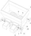
a novel biomass pellet fuel granulating and forming machine comprises a storage bin of the forming machine, wherein a discharge bin is arranged at the bottom of the storage bin and is communicated with the interior of the discharge bin, the novel biomass pellet fuel granulating and forming machine also comprises a crushing bin arranged between the storage bin and the discharge bin, the crushing bin is communicated with the interior of the storage bin and the interior of the discharge bin, two rollers are symmetrically and rotatably connected in the crushing bin through mounting rotating shafts, a plurality of sharp blocks stretching over the axial length of the rollers are arranged on the peripheral surfaces of the two rollers along the axial array of the sharp blocks, the cross sections of the sharp blocks are generally triangular, the sharp portions of the sharp blocks face the opposite sides of the two rollers, the axial direction of the rollers is perpendicular to the length direction of the crushing bin, four mounting plates are arranged on the two opposite outer walls of the crushing bin, two ends of the rotating shafts penetrate through the outer, and the two speed reducing motors respectively drive the two rollers to rotate.
Further, the rotating shaft is rotatably connected to the mounting plate through a mounting bearing.
Further, mounting panel sliding connection just is driven its horizontal migration on smashing the storehouse outer wall by adjusting device on smashing the storehouse, adjusts two running roller axial interval corresponds be equipped with the waist type groove that supplies the pivot to pass through freely on smashing the storehouse outer wall.
Furthermore, two by two spacing fixture blocks are arranged on the outer wall of the crushing bin in pairs, and the corresponding mounting plate is provided with spacing clamping grooves for clamping the spacing fixture blocks and enabling the spacing fixture blocks to horizontally and freely slide.
Further, adjusting device is including rotating seat, screw rod, it is equipped with four to rotate the seat, its rigid coupling is in smash on the storehouse outer wall and corresponding with four mounting panels, the screw rod screw thread pierces through and rotates the seat and rotate with the mounting panel and be connected.
Furthermore, the screw rod is coaxially provided with an annular clamping block, and the corresponding rotating seat is provided with a clamping groove which is used for the annular clamping block to be embedded and clamped and can freely rotate.
The utility model has the advantages that: the point piece that sets up on two running rollers, the running roller is when synchronous antiport, the raw materials gets into between two running rollers, the breakage through point piece, the raw materials that makes the caking produces the breakage, the efficiency of sequent pelletization has been improved to at least a certain extent, workman's intensity of labour has also been reduced to at least a certain extent simultaneously, and work efficiency has been improved, in addition, four mounting panels have still been set up and have been driven the removal through adjusting device, make the interval between two running rollers can adjust, can adapt to the raw materials of different particle diameters on the one hand, on the other hand is through two running roller interval adjustments, the feeding speed of raw materials also can be adjusted to a certain extent, satisfy different production demands.
Drawings
In order to more clearly illustrate the technical solutions of the embodiments of the present invention, the drawings used in the description of the embodiments will be briefly introduced below, and it is obvious that the drawings in the following description are only some embodiments of the present invention, and it is obvious for those skilled in the art that other drawings can be obtained according to these drawings without creative efforts.
Fig. 1 is a schematic perspective view of the present invention;
FIG. 2 is a schematic top view of the three-dimensional structure of FIG. 1;
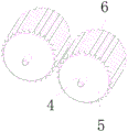
FIG. 3 is a schematic view of the three-dimensional structure of the middle roller of the present invention;
the reference numerals are explained below:
1-storage bin, 2-discharge bin, 3-crushing bin, 4-rotating shaft, 5-roller, 6-sharp block, 7-mounting plate, 8-speed reducing motor, 9-waist-shaped groove, 10-rotating seat, 11-screw, 12-annular clamping block, 13-clamping groove and 14-limiting clamping block.
Detailed Description
In order to make the technical means, creation features, achievement purposes and functions of the present invention easy to understand, the drawings in the embodiments of the present invention are combined below to clearly and completely describe the technical solutions in the embodiments of the present invention, and obviously, the described embodiments are only some embodiments of the present invention, not all embodiments. Based on the embodiments of the present invention, all other embodiments obtained by a person of ordinary skill in the art without creative efforts belong to the protection scope of the present invention.
As shown in fig. 1-3, a novel biomass pellet fuel granulating and forming machine comprises a storage bin 1 of the forming machine, wherein a discharge bin 2 is arranged at the bottom of the storage bin 1, the storage bin 1 is communicated with the inside of the discharge bin 2, the novel biomass pellet fuel granulating and forming machine further comprises a crushing bin 3 arranged between the storage bin 1 and the discharge bin 2, the crushing bin 3 is communicated with the inside of the storage bin 1 and the inside of the discharge bin 2, two rollers 5 are symmetrically and rotatably connected in the crushing bin 3 through a mounting rotating shaft 4, specifically, the rotating shaft 4 is rotatably connected on a mounting plate 7 through a mounting bearing, a plurality of sharp blocks 6 spanning the axial length of the rollers 5 are arranged on the circumferential surface of the two rollers 5 along the axial array, the cross section of each sharp block 6 is generally triangular, the sharp portions face the opposite sides of the two rollers 5, the axial direction of each roller 5 is perpendicular to the length direction of the crushing bin 3, four, two 4 both ends of pivot are worn out and are smashed 3 outer walls of storehouse and rotate respectively and connect on four mounting panels 7, wherein two install gear motor 8 on the mounting panel 7, two gear motor 8 drives two running rollers 5 respectively and rotate, further, mounting panel 7 sliding connection just is driven its horizontal migration on smashing 3 outer walls of storehouse by adjusting device on smashing storehouse 3, adjusts two running roller 5 axial interval, it is corresponding smash be equipped with on the 3 outer walls of storehouse and supply the pivot 4 waist type groove 9 that freely passes through, it is equipped with spacing fixture block 14 in pairs to smash two liang on the 3 outer walls of storehouse, corresponds be equipped with on the mounting panel 7 and supply spacing fixture block 14 block and can the horizontal spacing draw-in groove that freely slides, through the block effect of spacing draw-in groove on mounting panel 7 and spacing fixture block 14 for mounting panel 7 sliding connection is on smashing storehouse 3, adjusting device is including rotating seat 10, two, Screw rod 11, it is equipped with four to rotate seat 10, and its rigid coupling is in smash on the 3 outer walls in storehouse and corresponding with four mounting panels 7, screw rod 11 screw thread pierces through and rotates seat 10 and rotate with mounting panels 7 and be connected, and is concrete, the coaxial annular fixture block 12 that is equipped with on the screw rod 11, it is corresponding rotate seat 10 and go up to open and to have the draw-in groove 13 that supplies annular fixture block 12 to inlay the card, and can free rotation, it is spacing at draw-in groove 13 internal rotation through annular fixture block 12 for screw rod 11 rotates and connects on mounting panels 7.
The utility model discloses when using: switching on an external power supply, starting two speed reducing motors, reversely rotating the two speed reducing motors by the prior art, further synchronously reversely rotating the two rollers, rotating the two rollers to opposite sides of the two rollers, pouring the raw materials into a storage bin, falling onto the two rollers under the action of gravity, driving the raw materials to be between the two rollers along with the rotation of the two rollers, crushing the caked raw materials by crushing a sharp block so that the raw materials basically do not generate caking phenomenon, falling the crushed raw materials into a discharge bin, falling onto a feeding port of an external forming machine from the discharge bin, granulating and forming, synchronously rotating two screw rods on the same side (one side in the length direction of the crushing bin) by at least one worker when adjusting the distance between the two rollers, rotationally closing the screw rods and a rotating seat to drive a mounting plate to move, and driving the mounting plate to move by a vernier caliper or other measuring tools, the moving distance of the mounting plates is detected, then the two screw rods on the other side are synchronously rotated, the other two mounting plates are moved, and the moving distance is detected, so that the distance between the two rollers is adjusted, the raw materials with different particle diameters can be crushed, the time of the raw materials passing through the two rollers can be adjusted by adjusting the distance, and the feeding speed of the forming machine can be adjusted.
The preferred embodiments of the present invention disclosed above are intended only to help illustrate the present invention. The preferred embodiments are not intended to be exhaustive or to limit the invention to the precise embodiments disclosed. Obviously, many modifications and variations are possible in light of the above teaching. The embodiments were chosen and described in order to best explain the principles of the invention and its practical applications, to thereby enable others skilled in the art to best understand the invention for and utilize the invention. The present invention is limited only by the claims and their full scope and equivalents.
Claims (6)
1. A novel biomass pellet fuel granulating and forming machine comprises a storage bin (1) of a forming machine, wherein a discharge bin (2) is arranged at the bottom of the storage bin (1), the storage bin (1) is communicated with the inside of the discharge bin (2), the novel biomass pellet fuel granulating and forming machine is characterized by further comprising a crushing bin (3) arranged between the storage bin (1) and the discharge bin (2), the crushing bin (3) is communicated with the insides of the storage bin (1) and the discharge bin (2), two rollers (5) are symmetrically and rotatably connected in the crushing bin (3) through mounting rotating shafts (4), a plurality of sharp blocks (6) stretching over the axial length of the rollers (5) are arranged on the peripheral surface of the two rollers (5) along the axial array of the sharp blocks, the cross sections of the sharp blocks (6) are generally triangular, the sharp portions of the sharp blocks face the opposite sides of the two rollers (5), and the rollers (5) axially and vertically, smash storehouse (3) double-phase be equipped with four mounting panel (7) on the relative outer wall, two pivot (4) both ends are worn out and are smashed storehouse (3) outer wall and rotate respectively and connect on four mounting panel (7), wherein two install gear motor (8), two on mounting panel (7) gear motor (8) drive two running rollers (5) respectively and rotate.
2. The new biomass pellet fuel pelletizing and forming machine according to claim 1 is characterized in that the rotating shaft (4) is rotatably connected to the mounting plate (7) through a mounting bearing.
3. The novel biomass pellet fuel granulating and forming machine as claimed in claim 1, wherein the mounting plate (7) is slidably connected to the pulverizing bin (3) and is driven by an adjusting device to horizontally move on the outer wall of the pulverizing bin (3), the axial distance between the two rollers (5) is adjusted, and a waist-shaped groove (9) for the rotating shaft (4) to freely pass through is formed in the outer wall of the corresponding pulverizing bin (3).
4. The novel biomass pellet fuel granulating and forming machine as claimed in claim 3, wherein the outer wall of the pulverizing bin (3) is provided with two limiting clamping blocks (14) in pairs, and the corresponding mounting plate (7) is provided with limiting clamping grooves for clamping the limiting clamping blocks (14) and allowing the limiting clamping blocks to slide horizontally and freely.
5. The novel biomass pellet fuel granulating and forming machine as claimed in claim 3, wherein the adjusting device comprises four rotating seats (10) and four screws (11), the four rotating seats (10) are fixedly connected to the outer wall of the crushing bin (3) and correspond to the four mounting plates (7), and the screws (11) penetrate through the rotating seats (10) and are rotatably connected with the mounting plates (7).
6. The novel biomass pellet fuel granulating and forming machine as claimed in claim 5, wherein the screw (11) is coaxially provided with an annular clamping block (12), and the corresponding rotating seat (10) is provided with a clamping groove (13) which is used for the annular clamping block (12) to be clamped and can freely rotate.
Priority Applications (1)
| Application Number | Priority Date | Filing Date | Title |
|---|---|---|---|
| CN201921450604.0U CN210683719U (en) | 2019-09-01 | 2019-09-01 | Novel biomass pellet fuel granulating and forming machine |
Applications Claiming Priority (1)
| Application Number | Priority Date | Filing Date | Title |
|---|---|---|---|
| CN201921450604.0U CN210683719U (en) | 2019-09-01 | 2019-09-01 | Novel biomass pellet fuel granulating and forming machine |
Publications (1)
| Publication Number | Publication Date |
|---|---|
| CN210683719U true CN210683719U (en) | 2020-06-05 |
Family
ID=70892830
Family Applications (1)
| Application Number | Title | Priority Date | Filing Date |
|---|---|---|---|
| CN201921450604.0U Expired - Fee Related CN210683719U (en) | 2019-09-01 | 2019-09-01 | Novel biomass pellet fuel granulating and forming machine |
Country Status (1)
| Country | Link |
|---|---|
| CN (1) | CN210683719U (en) |
Cited By (1)
| Publication number | Priority date | Publication date | Assignee | Title |
|---|---|---|---|---|
| CN112237886A (en) * | 2020-10-30 | 2021-01-19 | 桃江县新辉生物质颗粒有限公司 | Self-drying type biomass particle granulating device |
-
2019
- 2019-09-01 CN CN201921450604.0U patent/CN210683719U/en not_active Expired - Fee Related
Cited By (1)
| Publication number | Priority date | Publication date | Assignee | Title |
|---|---|---|---|---|
| CN112237886A (en) * | 2020-10-30 | 2021-01-19 | 桃江县新辉生物质颗粒有限公司 | Self-drying type biomass particle granulating device |
Similar Documents
| Publication | Publication Date | Title |
|---|---|---|
| CN202191938U (en) | Ball mill adopting wet method | |
| CN107715796A (en) | A kind of mobile biomass granulator for the processing of agricultural waste | |
| CN107120930A (en) | It is a kind of that there is the biomass material drying equipment for being moved easily function | |
| CN210683719U (en) | Novel biomass pellet fuel granulating and forming machine | |
| CN203726868U (en) | Smashing and forming system for straw-type biomass | |
| CN203704598U (en) | Drying system for producing fertilizer by using waste tobacco leaves | |
| CN206492986U (en) | A kind of pipe cutting equipment with anti-loosening function | |
| CN202398345U (en) | Sludge pelletizing arch-breaking device | |
| CN204710514U (en) | A kind of industrial layering material-pulverizing device | |
| CN205797396U (en) | It is applicable to the reducing mechanism of rice husk | |
| CN202654994U (en) | Energy-saving efficient biomass fuel particle complete producing equipment | |
| CN112473901B (en) | Pretreatment device capable of being driven by solar energy for biomass fuel | |
| CN109608091B (en) | Heating furnace ash retreatment process | |
| CN203190420U (en) | Feeding device of vertical type rotation pyrolyzation gasification incinerator | |
| CN200966997Y (en) | Hammer crushing winnower | |
| CN204338291U (en) | A kind of high-efficiency vertical mill | |
| CN202805696U (en) | Extrusion separation device used for realizing dry-wet separation on municipal household waste | |
| CN204122176U (en) | Solar light-heat power-generation horizontal-type biaxial phase change medium reducing mechanism | |
| CN203591930U (en) | Bouncing sorting machine for household garbage | |
| CN207769872U (en) | A kind of biomass fuel mixing arrangement | |
| CN203726869U (en) | Smashed material forming machine for straw-type biomass | |
| CN202430140U (en) | Dryer on compound fertilizer production line | |
| CN208711899U (en) | A kind of feed grinding mill with drying function | |
| CN203316088U (en) | Pelletizer of sugarcane leaves | |
| CN202829810U (en) | Spherical bead processing unit |
Legal Events
| Date | Code | Title | Description |
|---|---|---|---|
| GR01 | Patent grant | ||
| GR01 | Patent grant | ||
| CF01 | Termination of patent right due to non-payment of annual fee | ||
| CF01 | Termination of patent right due to non-payment of annual fee |
Granted publication date: 20200605 Termination date: 20210901 |