CN210679492U - Injection mold slider bottom advances gluey mechanism - Google Patents
Injection mold slider bottom advances gluey mechanism Download PDFInfo
- Publication number
- CN210679492U CN210679492U CN201921449993.5U CN201921449993U CN210679492U CN 210679492 U CN210679492 U CN 210679492U CN 201921449993 U CN201921449993 U CN 201921449993U CN 210679492 U CN210679492 U CN 210679492U
- Authority
- CN
- China
- Prior art keywords
- plate
- pouring gate
- block
- sliding block
- runner
- Prior art date
- Legal status (The legal status is an assumption and is not a legal conclusion. Google has not performed a legal analysis and makes no representation as to the accuracy of the status listed.)
- Active
Links
Images


Abstract
A glue feeding mechanism at the bottom of a sliding block of an injection mold comprises an upper compound plate, a lower compound plate, a runner plate, a fixed mold plate, a heat nozzle, a mold pin, an upper ejector plate, a lower ejector plate, a straight ejector rod and an inclined ejector rod, wherein the runner plate is arranged below the upper compound plate, the fixed mold plate is arranged below the upper compound plate, the inclined ejector rod is provided with an inclined ejector block, a movable mold plate is arranged on the mold pin, a plastic piece is arranged between the movable mold plate and the fixed mold plate, a flanging is arranged, an inner groove is formed in the inner wall of the flanging, a sliding block is arranged below the fixed mold plate, a through hole and an inclined guide hole are formed in the sliding block, a convex block is arranged below the fixed mold plate and inserted into the through hole, a pouring gate is formed between the sliding block and the movable mold plate and the inclined ejector block, the pouring gate comprises a transverse pouring gate at the bottom, one end of the transverse gate corresponds to the heat nozzle, the lower end of the spring is in contact with the sliding block, the sliding block is provided with a limiting pull groove, and the limiting pull hook is matched with the limiting pull groove.
Description
Technical Field
The utility model relates to an injection mold especially relates to injection mold slider bottom advances gluey mechanism.
Background
Injection molds are one type of mold and are used very commonly, especially most often in the manufacture of some plastic parts. At present, the product is glued by the glue inlet and must be glued on the parting surface of the sliding block, the glue inlet is arranged on the appearance surface or is close to the appearance surface, and the molded product usually has the following appearance problems near the glue inlet: 1. the glue inlet often generates the problems of fog spots, impact marks, shrinkage depressions and the like, and the appearance surface of the product is directly influenced; 2. the glue is fed into the side of the product, the glue opening needs to be trimmed, the production efficiency is reduced, and the appearance quality of the product is influenced due to the quality of the trimmed glue.
Disclosure of Invention
The utility model aims at overcoming the shortcoming that prior art exists, provide a slider bottom advances to glue, guarantee that the product appearance is pleasing to the eye, improve production efficiency's injection mold slider bottom and advance gluey mechanism.
The utility model discloses injection mold slider bottom advances gluey technical scheme of mechanism is: the hot runner injection molding device comprises an upper compound plate and a lower compound plate, wherein a runner plate is arranged below the upper compound plate, a hot runner is arranged in the runner plate, a fixed template is arranged below the runner plate, a hot nozzle is arranged in the fixed template, mold feet are arranged on the lower compound plate, an upper ejector plate, a lower ejector plate, a straight ejector rod and an inclined ejector rod are arranged on the lower compound plate between the mold feet, an inclined ejector block is arranged on the inclined ejector rod, a movable template is arranged on the mold feet, an injection molding plastic piece is arranged between the movable template and the fixed template, a downward and obliquely inward flanging is formed on one side of the plastic piece, an inner groove is formed on the inner wall of the flanging, the inclined ejector block is matched with the inner groove, a slide block is arranged below the fixed template, a through hole and an inclined guide hole are formed in the slide block, a convex block is arranged below the fixed template, the convex block is inserted into the through hole, the hot nozzle is arranged in the fixed template at the position of the convex block, a, one end of the transverse pouring gate corresponds to the hot nozzle, the other end of the transverse pouring gate is connected with a vertical pouring gate which is vertically upward, the vertical pouring gate is connected with an inclined pouring gate which inclines upward, the inclined pouring gate corresponds to the lower end face of the turned edge of the plastic part, the fixed die plate is internally provided with an inclined guide pillar, a spring and a limiting drag hook, the inclined guide pillar is matched with an inclined guide hole of the sliding block, the lower end of the spring is contacted with the sliding block, the outer wall of the sliding block is provided with a limiting pull groove, and the limiting drag hook is matched.
The utility model discloses a plastic piece injection mold slider bottom advances gluey mechanism, after the plastic piece injection moulding, lower compound board drives the mould foot, go up the thimble board, lower thimble board, straight ejector pin, oblique ejector pin, movable mould board and plastic piece and moves down together, and go up compound board, runner plate and fixed mould board and keep motionless, make the mould from fixed mould board and movable mould board department die sinking, when the movable mould board moves down, the spring pushes the slider downwards under the effect of elasticity, make the slider follow the movable mould board and move down together, the slider pushes down runner department sizing material, make the hot mouth of fixed mould board break apart with runner department sizing material, oblique guide pillar and the oblique guide hole cooperation of slider in the fixed mould board simultaneously, make the slider move outwards when moving down, the slider deviates from a turn-ups outer wall that heels downwards, when the spacing kerve of slider outer wall moves down to contact with the spacing drag hook of fixed mould board, the limiting pull groove of the sliding block is pulled by the limiting pull hook, the sliding block stops moving downwards, the movable template continues moving downwards, the sliding block is also separated from a rubber material at the pouring gate, finally, the upper ejector plate and the lower ejector plate drive the straight ejector rod and the inclined ejector rod, the inclined ejector rod drives the inclined ejector block to be separated from the inner groove of the plastic part, and the straight ejector rod ejects the plastic part for demolding. This scheme injection mold slider bottom advances gluey mechanism, mainly be the runner that sets up the formula of hiding between the bottom of slider and movable mould board, this runner is by horizontal runner, vertical runner and slant runner are constituteed, and it has the perforation to be located horizontal runner position system at the slider, the tip communicates with each other with horizontal runner through this perforation under the hot mouth in the fixed die plate, horizontal runner avoids oblique kicking block structure through vertical runner and slant runner, it is corresponding with the turn-ups lower terminal surface of working of plastics, the advantage of this structure is: firstly, by adopting the submarine gate form, the glue opening is transversely arranged on the back surface of the product (far away from the appearance area of the product), the parting surface and the assembly surface of the product are avoided, the surface of the plastic part has no problems of fog spots, impact marks or shrinkage and depression, the plastic part has attractive appearance, the gate and the plastic part can be directly broken off, the separation is easy, the position of the glue opening of the product is not required to be trimmed, and the production efficiency is improved; and secondly, a through hole is formed in the sliding block, the convex block of the fixed template is inserted into the through hole, the hot nozzle is communicated with the pouring gate through the position, the hot nozzle is automatically separated from the pouring gate after the mold is opened, the sliding block firstly moves downwards along with the movable template, and after the sliding block is separated from the outer wall of the downward and inclined inward flanging of the plastic part, the sliding block stops moving under the action of the limiting drag hook and the limiting pull groove, so that the submarine pouring gate and the plastic part can be smoothly demoulded.
The utility model discloses injection mold slider bottom advances gluey mechanism, the spring be nitrogen spring. The nitrogen spring is cleaner, efficient and space-saving. And wear-resistant blocks are arranged on the outer wall of the sliding block and above the movable template. Because during the die sinking, the slider needs to follow the movable mould board earlier and move together, and moves to the outside simultaneously, consequently sets up wear-resisting piece on slider outer wall and movable mould board, makes between slider outer wall and the fixed die plate stand wear and tear more to and stand wear and tear more between slider bottom surface and the movable mould board.
Drawings
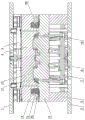
FIG. 1 is a schematic structural view of a bottom glue feeding mechanism of a slide block of the injection mold of the present invention;
FIG. 2 is a schematic structural diagram of the matched state of a fixed mold plate, a movable mold plate, a slide block, a hot nozzle, a sprue, a plastic part, an inclined ejector rod and an inclined ejector block;
FIG. 3 is an enlarged view of a portion of FIG. 2 at A;
FIG. 4 is a schematic structural diagram of the fixed die plate, the movable die plate, the slide block, the inclined guide post, the inclined ejector block and the spring in a matching state;
fig. 5 is a perspective view of the movable mold plate with the slide block, the inclined guide rod and the spring in cooperation.
Detailed Description
The utility model relates to a plastic injection mold slider bottom glue feeding mechanism, as shown in figures 1-5, comprising an upper compound plate 1 and a lower compound plate 2, a runner plate 3 is arranged under the upper compound plate, a hot runner is arranged in the runner plate, a fixed template 4 is arranged under the runner plate, a hot nozzle 5 is arranged in the fixed template, a mold foot 6 is arranged on the lower compound plate, an upper thimble plate 7, a lower thimble plate 8, a straight ejector rod and an oblique ejector rod 10 are arranged on the lower compound plate between the mold feet, an oblique ejector block 11 is arranged on the oblique ejector rod, a movable template 12 is arranged on the mold foot, an injection molded plastic piece 13 is arranged between the movable template and the fixed template, one side of the plastic piece is provided with a downward and oblique inward flange 14, the flange inner wall forms a groove 15, the oblique ejector block 11 is matched with the inner groove, a slider 16 is arranged in the fixed template 4, a perforation 17 and an oblique guide hole 18 are arranged in the slider, a lug 19 is arranged under the fixed template, the lug is inserted into the, the hot nozzle 5 is arranged in the fixed die plate 4 at the position of the convex block, a pouring gate is formed between the lower end of the sliding block 16 and the movable die plate 12 as well as the inclined ejector block 11, the pouring gate comprises a transverse pouring gate 20 at the bottom, one end of the transverse pouring gate corresponds to the hot nozzle, the other end of the transverse pouring gate is connected with a vertical pouring gate 21 which is upward vertically, the vertical pouring gate is connected with an inclined pouring gate 22 which is inclined upward, the inclined pouring gate corresponds to the lower end face of the flanging 14 of the plastic part 13, an inclined guide pillar 23, a spring 24 and a limiting pull hook 25 are arranged in the fixed die plate 4, the inclined guide pillar is matched with an inclined guide hole 18 of the sliding block 16, the lower end of the spring is contacted with the sliding block, a limiting pull groove. After the plastic part 13 is injection molded, the lower compound plate 2 drives the mold legs 6, the upper ejector pin plate 7, the lower ejector pin plate 8, the straight ejector pins, the inclined ejector pins 10, the movable mold plate 12 and the plastic part 13 to move downwards together, the upper compound plate 1, the runner plate 3 and the fixed mold plate 4 are kept still, so that the mold is opened from the fixed mold plate 4 and the movable mold plate 12, when the movable mold plate moves downwards, the spring 24 pushes the slide block 16 downwards under the action of elastic force, so that the slide block moves downwards along with the movable mold plate 12, the slide block 16 presses the sizing material at the sprue gate, the hot nozzle 5 of the fixed mold plate 4 is broken and separated from the sizing material at the sprue gate, meanwhile, the inclined guide post 23 in the fixed mold plate 4 is matched with the inclined guide hole 18 of the slide block 16, so that the slide block 16 moves outwards while moving downwards, the outer wall of the downward flanging 14 on one side of the slide block 13 inclines, when the limit pull groove 26 of the outer wall of the, the limiting draw groove 26 of the sliding block 16 is pulled by the limiting draw hook 25, the sliding block stops moving downwards, the movable template 12 continues moving downwards, the sliding block is separated from the rubber material at the pouring gate, finally, the upper ejector plate 7 and the lower ejector plate 8 drive the straight ejector rod and the inclined ejector rod 10, the inclined ejector rod drives the inclined ejector block 11 to be separated from the inner groove 15 of the plastic part 13, and the straight ejector rod ejects and releases the plastic part. This scheme injection mold slider bottom advances gluey mechanism, mainly be the runner that sets up the formula of hiding between slider 16's bottom and movable mould board 12, this runner is by horizontal runner 20, vertical runner 21 and slant runner 22 are constituteed, and it has perforation 17 to be located horizontal runner 20 position system at slider 16, the tip communicates with each other with horizontal runner 20 through this perforation 17 with 5 lower tip of hot mouth in the fixed mould board 4, horizontal runner is through vertical runner 21 and slant runner 22 and is avoided oblique kicking block 11 structure, it is corresponding with the turn-ups 14 lower terminal surface of working of plastics 13, the advantage of this structure is: firstly, by adopting the submarine gate form, the glue port is transversely arranged on the back surface of the product (far away from the appearance area of the product), the parting surface and the assembly surface of the product are avoided, the surface of the plastic part 13 has no problems of fog spots, impact marks or shrinkage depressions and the like, the appearance of the plastic part is attractive, the gate and the plastic part can be directly broken off, the separation is easy, the position of the glue port of the product is not required to be trimmed, and the production efficiency is improved; secondly, a through hole 17 is formed in the slide block 16, a convex block 19 of the fixed die plate 4 is inserted into the through hole, the hot nozzle 5 is communicated with the pouring gate through the position, the hot nozzle is automatically separated from the pouring gate after the die is opened, the slide block 16 firstly moves downwards along with the movable die plate 12, and after the slide block is separated from the outer wall of the downward and inclined inward flanging 14 of the plastic part 13, the slide block 16 stops moving under the action of the limiting draw hook 25 and the limiting draw groove 26, so that both the latent pouring gate and the plastic part can be smoothly demoulded. The spring 24 is a nitrogen spring. The nitrogen spring is cleaner, efficient and space-saving. And a wear-resistant block 27 is arranged on the outer wall of the sliding block 16 and above the movable template 12. Because the slide block 16 needs to move together with the movable die plate 12 and move outwards at the same time when the die is opened, the wear-resistant blocks 27 are arranged on the outer wall of the slide block and the movable die plate, so that the outer wall of the slide block and the fixed die plate 4 are more wear-resistant, and the bottom surface of the slide block 16 and the movable die plate 12 are more wear-resistant.
Claims (3)
1. Injection mold slider bottom advances gluey mechanism, including last compoboard (1) and lower compoboard (2), set up runner plate (3) under going up the compoboard, set up the hot runner in the runner plate, set up fixed die plate (4) under the runner plate, set up hot nozzle (5) in the fixed die plate, set up mold foot (6) on the compoboard down, set up thimble board (7) on the lower compoboard between the mold foot, thimble board (8) down, straight ejector pin and oblique ejector pin (10), set up oblique kicking block (11) on the oblique ejector pin, set up movable mould board (12) on the mold foot, there is injection moulding's working of plastics (13) between movable mould board and the fixed die plate, one side system of working of plastics has downwards and the inward turn-ups of slope (14), turn-ups inner wall forms inner groovy (15), oblique kicking block (11) cooperate with the inner groovy, its: a slide block (16) is arranged below the fixed die plate (4), a through hole (17) and an inclined guide hole (18) are formed in the slide block, a convex block (19) is formed below the fixed die plate and inserted into the through hole, the hot nozzle (5) is arranged in the fixed die plate (4) at the position of the convex block, a pouring gate is formed between the lower end of the slide block (16) and the movable die plate (12) as well as the inclined ejector block (11), the pouring gate comprises a transverse pouring gate (20) at the bottom, one end of the transverse pouring gate corresponds to the hot nozzle, the other end of the transverse pouring gate is connected with a vertical pouring gate (21) which is vertically upward, the vertical pouring gate is connected with an inclined pouring gate (22) which is inclined upward, an inclined pouring gate plastic piece corresponds to the lower end face of a flanging (14) of the plastic piece (13), an inclined guide pillar (23), a spring (24) and a limiting drag hook (25) are arranged in the fixed die, the lower end of the spring is contacted with the sliding block, the outer wall of the sliding block is provided with a limiting pull groove (26), and the limiting pull hook is matched with the limiting pull groove.
2. The injection mold slide block bottom glue feeding mechanism of claim 1, characterized in that: the spring (24) is a nitrogen spring.
3. The injection mold slide block bottom glue feeding mechanism of claim 1, characterized in that: and a wear-resistant block (27) is arranged above the outer wall of the sliding block (16) and the movable template (12).
Priority Applications (1)
| Application Number | Priority Date | Filing Date | Title |
|---|---|---|---|
| CN201921449993.5U CN210679492U (en) | 2019-09-03 | 2019-09-03 | Injection mold slider bottom advances gluey mechanism |
Applications Claiming Priority (1)
| Application Number | Priority Date | Filing Date | Title |
|---|---|---|---|
| CN201921449993.5U CN210679492U (en) | 2019-09-03 | 2019-09-03 | Injection mold slider bottom advances gluey mechanism |
Publications (1)
| Publication Number | Publication Date |
|---|---|
| CN210679492U true CN210679492U (en) | 2020-06-05 |
Family
ID=70903627
Family Applications (1)
| Application Number | Title | Priority Date | Filing Date |
|---|---|---|---|
| CN201921449993.5U Active CN210679492U (en) | 2019-09-03 | 2019-09-03 | Injection mold slider bottom advances gluey mechanism |
Country Status (1)
| Country | Link |
|---|---|
| CN (1) | CN210679492U (en) |
Cited By (2)
| Publication number | Priority date | Publication date | Assignee | Title |
|---|---|---|---|---|
| CN110435085A (en) * | 2019-09-03 | 2019-11-12 | 滨海模塑集团有限公司 | Injection mould slide block bottom glue-feeding mechanism |
| CN111976103A (en) * | 2020-07-23 | 2020-11-24 | 遵义群建塑胶制品有限公司 | Glue feeding device for submarine side gate |
-
2019
- 2019-09-03 CN CN201921449993.5U patent/CN210679492U/en active Active
Cited By (2)
| Publication number | Priority date | Publication date | Assignee | Title |
|---|---|---|---|---|
| CN110435085A (en) * | 2019-09-03 | 2019-11-12 | 滨海模塑集团有限公司 | Injection mould slide block bottom glue-feeding mechanism |
| CN111976103A (en) * | 2020-07-23 | 2020-11-24 | 遵义群建塑胶制品有限公司 | Glue feeding device for submarine side gate |
Similar Documents
| Publication | Publication Date | Title |
|---|---|---|
| CN201366773Y (en) | Internal dividing type bumper plastic mold | |
| CN104985775A (en) | Straight-ejecting, oblique-slipping and core-pulling synchronously combined sliding block mechanism of injection mold | |
| CN210679492U (en) | Injection mold slider bottom advances gluey mechanism | |
| CN210415374U (en) | Injection mold oblique top spring combination long distance side mechanism of loosing core | |
| CN205467128U (en) | Segmentation drawing of patterns injection mold | |
| CN204196152U (en) | A kind of double-joint type slide block demolding mechanism | |
| CN103737824B (en) | The parallel-moving type precision die of hiding of cells in notebook computer lid | |
| CN207841953U (en) | Injection mold is hidden into plastic structure | |
| CN215825851U (en) | Air-line-preventing glue feeding structure of injection mold | |
| CN211105381U (en) | Injection mold slider formula pushes up mechanism to one side | |
| CN213082231U (en) | Flip-chip mould ejection mechanism | |
| CN210082315U (en) | Core-pulling pouring gate structure for molding lens | |
| CN210705828U (en) | Three-stage sliding block demoulding mechanism with large-angle back-off mould | |
| CN110757745B (en) | Secondary ejection core-pulling structure of spoiler support mold | |
| CN204820224U (en) | Injection mold directly pushes up oblique cunning and looses core and make up slider mechanism in step | |
| CN210679526U (en) | Outer core-pulling mechanism for fixed die side inclined guide pillar of injection mold | |
| CN213891090U (en) | Demoulding mechanism for submarine gate in injection mould sliding block | |
| CN211868508U (en) | Novel injection mold with product opening edge arranged at water gap | |
| CN218593602U (en) | Injection mold demoulding mechanism for lower guard plate of instrument desk | |
| CN211842985U (en) | Quick-assembling die with floating inclined drawer and matched ejection structure | |
| CN210415376U (en) | Guide wear-resistant mechanism of side core-pulling sliding block of injection mold | |
| CN218399296U (en) | Plastic barrel cover injection mold demoulding mechanism with easily-torn piece | |
| CN217293348U (en) | Injection mold ejection mechanism with octagonal positioning function | |
| CN217495058U (en) | Straight top and slider combined mechanism | |
| CN214324078U (en) | Front mould inclined ejection mould |
Legal Events
| Date | Code | Title | Description |
|---|---|---|---|
| GR01 | Patent grant | ||
| GR01 | Patent grant |