CN210678869U - Wind-powered electricity generation blade overlap cutting device - Google Patents
Wind-powered electricity generation blade overlap cutting device Download PDFInfo
- Publication number
- CN210678869U CN210678869U CN201921244606.4U CN201921244606U CN210678869U CN 210678869 U CN210678869 U CN 210678869U CN 201921244606 U CN201921244606 U CN 201921244606U CN 210678869 U CN210678869 U CN 210678869U
- Authority
- CN
- China
- Prior art keywords
- threaded rod
- wind
- fixed mounting
- workstation
- cutting device
- Prior art date
- Legal status (The legal status is an assumption and is not a legal conclusion. Google has not performed a legal analysis and makes no representation as to the accuracy of the status listed.)
- Expired - Fee Related
Links
- 238000005520 cutting process Methods 0.000 title claims abstract description 21
- 230000005611 electricity Effects 0.000 title claims abstract description 16
- 210000002421 cell wall Anatomy 0.000 claims abstract 4
- 238000003825 pressing Methods 0.000 claims description 7
- 238000009434 installation Methods 0.000 abstract description 4
- 239000011435 rock Substances 0.000 abstract 1
- 239000002699 waste material Substances 0.000 description 5
- 238000004519 manufacturing process Methods 0.000 description 2
- 239000000463 material Substances 0.000 description 2
- 230000004075 alteration Effects 0.000 description 1
- 230000009286 beneficial effect Effects 0.000 description 1
- 230000003993 interaction Effects 0.000 description 1
- 238000000034 method Methods 0.000 description 1
- 238000012986 modification Methods 0.000 description 1
- 230000004048 modification Effects 0.000 description 1
- 238000000926 separation method Methods 0.000 description 1
- 238000006467 substitution reaction Methods 0.000 description 1
- -1 technology Substances 0.000 description 1
Images


Landscapes
- Wind Motors (AREA)
Abstract
The utility model discloses a wind-powered electricity generation blade overlap cutting device, including the workstation, top one side of workstation is seted up flutedly, and the both sides cell wall of recess alternates through inlaying the bearing of establishing and is connected with the threaded rod, and the one end of threaded rod alternates with step motor's output shaft and is connected, and step motor fixed mounting is in the motor inslot that groove one side cell wall was seted up, and the surface threaded connection of threaded rod has the connecting block. The utility model relates to a wind-powered electricity generation blade overlap cutting device, the electric hydraulic cylinder through installation of U type frame bottom promotes the clamp plate and removes, be convenient for carry on spacing fixed with the wind-powered electricity generation blade that needs the cutting overlap, avoid in the cutting process, the wind-powered electricity generation blade takes place to rock, cause wind-powered electricity generation blade to damage, step motor through the installation rotates and drives the threaded rod and rotate, rotate through the threaded rod and drive the connecting block at threaded rod surface reciprocating motion, drive the fixed block through the connecting block and remove, be convenient for carry out the overlap through the runner and cut.
Description
Technical Field
The utility model relates to a cutting device, in particular to wind-powered electricity generation blade overlap cutting device.
Background
At present, the fan blade market in China forms diversified main investment forms of foreign enterprises, civil enterprises, research institutions, marketing companies and the like. The foreign enterprises mainly comprise GE, LM, GAMESA, VESSTAT and the like, and the domestic enterprises are represented by new materials, medium materials, technology, medium voyage and medium-complex people in the era.
The existing wind power blade can generate the flash in the production process, the flash of the wind power blade is generally cut off manually, time and labor are consumed, and meanwhile, the wind power blade is easy to damage, so that the flash cutting device of the wind power blade is used.
SUMMERY OF THE UTILITY MODEL
An object of the utility model is to provide a wind-powered electricity generation blade overlap cutting device to current wind-powered electricity generation blade that proposes in solving above-mentioned background art can produce the overlap in process of production, and wind-powered electricity generation blade overlap is generally cut through the manual work, and the problem of wind-powered electricity generation blade is damaged easily simultaneously to consuming time power.
In order to achieve the above object, the utility model provides a following technical scheme: a wind power blade flash cutting device comprises a workbench, wherein one side of the top end of the workbench is provided with a groove, the groove walls on the two sides of the groove are alternately connected with a threaded rod through embedded bearings, one end of the threaded rod is alternately connected with an output shaft of a stepping motor, the stepping motor is fixedly arranged in a motor groove formed in the groove wall on one side of the groove, the surface of the threaded rod is in threaded connection with a connecting block, the top end of the connecting block is fixedly provided with a fixed block, one side of the fixed block is provided with a mounting groove, the inside of the mounting groove is fixedly provided with a driving motor, the output shaft of the driving motor is alternately connected with one end of a rotating shaft, the other end of the rotating shaft is sleeved with a rotating wheel, the middle part of the top end of the workbench is provided with a through hole, the other side of the top end, two the flexible end of electric hydraulic cylinder and the top both sides fixed connection of clamp plate, the middle part fixed mounting of workstation bottom has scrap collecting box, four equal fixed mounting in edge of workstation bottom has the supporting leg, four fixed mounting has the diaphragm between the supporting leg.
As a preferred technical scheme of the utility model, four the equal fixed mounting in bottom of supporting leg has the mount pad, four anti-skidding line has all been seted up to the bottom of mount pad.
As an optimal technical scheme of the utility model, two the bottom of clamp plate is all pasted and is equipped with anti-skidding rubber pad.
As an optimized technical scheme of the utility model, the runner is adjusted well with the position of through-hole.
As a preferred technical scheme of the utility model, one side fixed mounting of workstation has flush mounting plate of switch, electric hydraulic cylinder control switch, driving motor control switch and step motor control switch are installed respectively to flush mounting plate of switch's surface, electric hydraulic cylinder, driving motor and step motor are respectively through electric hydraulic cylinder control switch, driving motor control switch and step motor control switch and external power supply electric connection.
Compared with the prior art, the utility model discloses following beneficial effect has:
1. the pressing plate is pushed to move by the electric hydraulic cylinder arranged at the bottom end of the U-shaped frame, so that the wind power blade needing to be cut with flash can be limited and fixed conveniently, and the wind power blade is prevented from shaking in the cutting process to damage the wind power blade;
2. the step motor through the installation rotates and drives the threaded rod and rotate, rotates through the threaded rod and drives the connecting block at threaded rod surface reciprocating motion, drives the fixed block through the connecting block and removes, is convenient for carry out the overlap through the runner and cuts.
Drawings
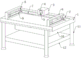
FIG. 1 is a schematic structural view of the present invention;
fig. 2 is a schematic side view of the present invention;
fig. 3 is a schematic view of a partial structure of the present invention.
In the figure: 1. a work table; 2. a groove; 3. a fixed block; 4. a rotating wheel; 5. a rotating shaft; 6. a U-shaped frame; 7. a through hole; 8. an electric hydraulic cylinder; 9. pressing a plate; 10. a waste collection tank; 11. supporting legs; 12. a transverse plate; 13. a drive motor; 14. a threaded rod; 15. a stepping motor; 16. connecting blocks; 17. a switch panel.
Detailed Description
The technical solutions in the embodiments of the present invention will be described clearly and completely with reference to the accompanying drawings in the embodiments of the present invention, and it is obvious that the described embodiments are only some embodiments of the present invention, not all embodiments. Based on the embodiments in the present invention, all other embodiments obtained by a person skilled in the art without creative work belong to the protection scope of the present invention.
Referring to fig. 1-3, the utility model provides a wind power blade flash cutting device, which comprises a workbench 1, a groove 2 is arranged on one side of the top end of the workbench 1, the two side walls of the groove 2 are connected with a threaded rod 14 through embedded bearings in an inserting way, one end of the threaded rod 14 is connected with an output shaft of a stepping motor 15 in an inserting way, the stepping motor 15 is fixedly arranged in a motor groove arranged on one side wall of the groove 2, the surface of the threaded rod 14 is connected with a connecting block 16 in a threaded way, the top end of the connecting block 16 is fixedly provided with a fixed block 3, one side of the fixed block 3 is provided with a mounting groove, the inside of the mounting groove is fixedly provided with a driving motor 13, the output shaft of the driving motor 13 is connected with one end of a rotating shaft 5 in an inserting way, the other end of the rotating shaft 5 is sleeved with, two electric hydraulic cylinders 8 are fixedly mounted on two sides of the bottom end of the two U-shaped frames 6, the telescopic ends of the two electric hydraulic cylinders 8 are fixedly connected with two sides of the top end of the pressing plate 9, a waste collecting box 10 is fixedly mounted in the middle of the bottom end of the workbench 1, supporting legs 11 are fixedly mounted on four corners of the bottom end of the workbench 1, and transverse plates 12 are fixedly mounted among the four supporting legs 11.
Preferably, the equal fixed mounting in bottom of four supporting legs 11 has the mount pad, and anti-skidding line has all been seted up to the bottom of four mount pads, through the mount pad of installation, and the supporting leg 11 of being convenient for is firmly fixed with ground.
Preferably, the bottom ends of the two pressing plates 9 are all provided with anti-skid rubber pads in a sticking mode, and the wind power blades are effectively protected through the anti-skid rubber pads.
Preferably, the rotating wheel 4 is aligned with the through hole 7, and the waste material is conveniently dropped to the waste material collecting box 10 through the alignment of the rotating wheel 4 and the through hole 7.
Preferably, a switch panel 17 is fixedly mounted on one side of the workbench 1, an electric hydraulic cylinder control switch, a driving motor control switch and a stepping motor control switch are respectively mounted on the surface of the switch panel 17, and the electric hydraulic cylinder 8, the driving motor 13 and the stepping motor 15 are respectively electrically connected with an external power supply through the electric hydraulic cylinder control switch, the driving motor control switch and the stepping motor control switch.
When the device is used, firstly, the wind power blade with the flash is placed inside the two U-shaped frames 6, the flash is aligned with the through hole 7, then the electric hydraulic cylinder 8 is opened through the electric hydraulic cylinder control switch, the pressing plate 9 is pushed to move through the electric hydraulic cylinder 8, the wind power blade is limited and fixed through the movement of the pressing plate 9, then the stepping motor 15 and the driving motor 13 are respectively opened through the stepping motor control switch and the driving motor control switch, the threaded rod 14 is driven to rotate through the rotation of the stepping motor 15, the connecting block 16 on the surface of the threaded rod 14 is driven to move through the rotation of the threaded rod 14, the fixed block 3 is driven to move through the movement of the connecting block 16, thereby the rotating wheel 4 is driven to move, and the rotating shaft 5 is driven to rotate through the rotation of the driving motor 13, rotate through pivot 5 and drive runner 4 and rotate, cut the overlap through runner 4, the waste material that the cutting produced falls into and collects in garbage collection box 10, after the cutting of accomplishing wind-powered electricity generation blade overlap, closes electric hydraulic cylinder 8 through electric hydraulic cylinder control switch, and electric hydraulic cylinder 8 shrink drives clamp plate 9 and wind-powered electricity generation blade separation, takes out the wind-powered electricity generation blade that the cutting was accomplished after that.
In the description of the present invention, it should be understood that the indicated orientation or positional relationship is based on the orientation or positional relationship shown in the drawings, and is only for convenience of description and simplification of description, and does not indicate or imply that the indicated device or element must have a particular orientation, be constructed and operated in a particular orientation, and thus should not be construed as limiting the present invention.
In the present invention, unless otherwise explicitly specified or limited, for example, it may be fixedly connected, detachably connected, or integrated; can be mechanically or electrically connected; they may be directly connected or indirectly connected through an intermediate medium, and may be connected through the inside of two elements or in an interaction relationship between two elements, unless otherwise specifically defined, and the specific meaning of the above terms in the present invention will be understood by those skilled in the art according to specific situations.
Although embodiments of the present invention have been shown and described, it will be appreciated by those skilled in the art that changes, modifications, substitutions and alterations can be made in these embodiments without departing from the principles and spirit of the invention, the scope of which is defined in the appended claims and their equivalents.
Claims (5)
1. The utility model provides a wind-powered electricity generation blade overlap cutting device, includes workstation (1), its characterized in that, top one side of workstation (1) is seted up recess (2), the both sides cell wall of recess (2) alternates through the bearing of inlaying and is connected with threaded rod (14), the one end of threaded rod (14) alternates with the output shaft of step motor (15) and is connected, step motor (15) fixed mounting is in the motor inslot that recess (2) one side cell wall was seted up, the surface threaded connection of threaded rod (14) has connecting block (16), the top fixed mounting of connecting block (16) has fixed block (3), the mounting groove has been seted up to one side of fixed block (3), the inside fixed mounting of mounting groove has driving motor (13), the output shaft of driving motor (13) alternates with the one end of pivot (5) and is connected, the other pot head of pivot (5) is equipped with runner (4), through-hole (7) have been seted up at the middle part on workstation (1) top, the opposite side fixed mounting on workstation (1) top has two U type framves (6), two the equal fixed mounting in bottom both sides of U type frame (6) has two electric hydraulic cylinder (8), two the flexible end of electric hydraulic cylinder (8) and the top both sides fixed connection of clamp plate (9), the middle part fixed mounting of workstation (1) bottom has scrap collecting box (10), four equal fixed mounting in four edges of workstation (1) bottom has supporting leg (11), four fixed mounting has diaphragm (12) between supporting leg (11).
2. The wind turbine blade flashing cutting device of claim 1, wherein: four the equal fixed mounting in bottom of supporting leg (11) has the mount pad, four anti-skidding line has all been seted up to the bottom of mount pad.
3. The wind turbine blade flashing cutting device of claim 1, wherein: the bottom ends of the two pressing plates (9) are all provided with anti-skidding rubber pads in an attached mode.
4. The wind turbine blade flashing cutting device of claim 1, wherein: the rotating wheel (4) is aligned with the through hole (7).
5. The wind turbine blade flashing cutting device of claim 1, wherein: one side fixed mounting of workstation (1) has flush mounting plate of switch (17), electric hydraulic cylinder control switch, driving motor control switch and step motor control switch are installed respectively to the surface of flush mounting plate of switch (17), electric hydraulic cylinder (8), driving motor (13) and step motor (15) are respectively through electric hydraulic cylinder control switch, driving motor control switch and step motor control switch and external power supply electric connection.
Priority Applications (1)
| Application Number | Priority Date | Filing Date | Title |
|---|---|---|---|
| CN201921244606.4U CN210678869U (en) | 2019-08-02 | 2019-08-02 | Wind-powered electricity generation blade overlap cutting device |
Applications Claiming Priority (1)
| Application Number | Priority Date | Filing Date | Title |
|---|---|---|---|
| CN201921244606.4U CN210678869U (en) | 2019-08-02 | 2019-08-02 | Wind-powered electricity generation blade overlap cutting device |
Publications (1)
| Publication Number | Publication Date |
|---|---|
| CN210678869U true CN210678869U (en) | 2020-06-05 |
Family
ID=70894319
Family Applications (1)
| Application Number | Title | Priority Date | Filing Date |
|---|---|---|---|
| CN201921244606.4U Expired - Fee Related CN210678869U (en) | 2019-08-02 | 2019-08-02 | Wind-powered electricity generation blade overlap cutting device |
Country Status (1)
| Country | Link |
|---|---|
| CN (1) | CN210678869U (en) |
Cited By (1)
| Publication number | Priority date | Publication date | Assignee | Title |
|---|---|---|---|---|
| CN114798695A (en) * | 2022-04-29 | 2022-07-29 | 丰诺(江苏)环保科技有限公司 | Retired wind power blade cutting device |
-
2019
- 2019-08-02 CN CN201921244606.4U patent/CN210678869U/en not_active Expired - Fee Related
Cited By (1)
| Publication number | Priority date | Publication date | Assignee | Title |
|---|---|---|---|---|
| CN114798695A (en) * | 2022-04-29 | 2022-07-29 | 丰诺(江苏)环保科技有限公司 | Retired wind power blade cutting device |
Similar Documents
| Publication | Publication Date | Title |
|---|---|---|
| CN210678869U (en) | Wind-powered electricity generation blade overlap cutting device | |
| CN201711298U (en) | Dust collection device for solar battery | |
| CN217282825U (en) | Photovoltaic power generation assembly mounting structure suitable for aerogenerator stake pole | |
| CN108774945B (en) | Pavement joint cutting device capable of adjusting joint cutting depth for concrete road construction | |
| CN202955603U (en) | Wind and photovoltaic hybrid streetlamp | |
| CN215265454U (en) | Energy-concerving and environment-protective advertising device | |
| CN115581005A (en) | Power dispatching control system with wind-light complementary structure | |
| CN210526123U (en) | Special drawing board for mechanical drawing | |
| CN210241422U (en) | Multipurpose solar energy intelligence street lamp | |
| CN203266718U (en) | Rotary type solar cell back film cutting device | |
| CN206286657U (en) | A kind of double portable electric files for frustrating optical mode | |
| CN221531413U (en) | Solar photovoltaic panel for photovoltaic power plant | |
| CN211413481U (en) | Cutting device for reinforcing steel bar for well lid production | |
| CN219550430U (en) | Lighting device convenient to clearance | |
| CN213585655U (en) | New forms of energy electricity generation is with solar photovoltaic board of angle adjustable is stabilized in installation | |
| CN215668917U (en) | Road maintenance auxiliary device based on big data platform | |
| CN214816483U (en) | Corner cutting device of steel construction | |
| CN212170527U (en) | Slitting device for wind driven generator blade web production | |
| CN217981413U (en) | Environment-friendly energy-saving outdoor fixed environment monitoring device | |
| CN219884050U (en) | Floating type water surface photovoltaic bracket | |
| CN211791359U (en) | New forms of energy solar panel protection device | |
| CN210669983U (en) | Photovoltaic power generation dust collector | |
| CN211604640U (en) | Environment-friendly and energy-saving conference management device | |
| CN210589597U (en) | Accurate long-life rubber processing equipment | |
| CN214446797U (en) | PE protection film cutting device with cutting efficiency is high |
Legal Events
| Date | Code | Title | Description |
|---|---|---|---|
| GR01 | Patent grant | ||
| GR01 | Patent grant | ||
| CF01 | Termination of patent right due to non-payment of annual fee |
Granted publication date: 20200605 |
|
| CF01 | Termination of patent right due to non-payment of annual fee |