CN210662586U - Electrical equipment bin and light reflecting component, lamp holder and street lamp using electrical equipment bin - Google Patents
Electrical equipment bin and light reflecting component, lamp holder and street lamp using electrical equipment bin Download PDFInfo
- Publication number
- CN210662586U CN210662586U CN201921357405.5U CN201921357405U CN210662586U CN 210662586 U CN210662586 U CN 210662586U CN 201921357405 U CN201921357405 U CN 201921357405U CN 210662586 U CN210662586 U CN 210662586U
- Authority
- CN
- China
- Prior art keywords
- cover
- electrical
- electrical cabinet
- bin
- main body
- Prior art date
- Legal status (The legal status is an assumption and is not a legal conclusion. Google has not performed a legal analysis and makes no representation as to the accuracy of the status listed.)
- Active
Links
Images


Abstract
The utility model discloses an electrical bin and a light reflecting component, a lamp holder and a street lamp using the electrical bin, wherein the battery bin comprises an electrical bin main body and an electrical bin cover made of non-metallic materials, the electrical bin cover is arranged on the electrical bin main body, and the space formed by the electrical bin cover is communicated with the space formed by the electrical bin main body; the electric appliance bin can effectively reduce the negative influence of the electric appliance bin on the shielding and reduction of the electromagnetic waves, and improve the transmission quality of the electromagnetic waves.
Description
[ technical field ] A method for producing a semiconductor device
The utility model relates to an outdoor lighting technology especially relates to an electrical apparatus storehouse and use reflective component, lamp holder and street lamp of this electrical apparatus storehouse.
[ background of the invention ]
The street lamp is used as a luminous lighting system on roads, streets and public squares, and plays a great role in the aspects of facilitating the lives of the masses, beautifying the cities, promoting the rapid development of the economy, improving the investment environment and the like.
At present, a common street lamp includes a lamp post and one or more street lamp caps installed on the lamp post, and the street lamp caps generally include a light-emitting component, a lamp shade, a power supply component (also called as a power driver or a power adapter, often referred to as a power supply in the industry), a base, a lamp cover, a reflective component, an electrical appliance cabin (used for installing the power supply component, a single-lamp controller, etc., which can be independently arranged, or can be a part of the reflective component), and the like. For example, the lamp cap and the street lamp using the lamp cap are named as 201810141395.5, the lamp cap and the street lamp using the lamp cap are named as 201910291773.2, and the lamp cap and the street lamp using the reflecting component are named as 201910291773.2.
Because the existing electrical equipment bin is basically made of metal materials, a certain shielding effect is achieved on the transmission of electromagnetic waves (wireless signals), the signals of the electromagnetic waves received and generated by a controller installed on the electrical equipment bin are reduced, and the response of the controller is influenced or interfered; but if the electrical bin is made of plastic materials, the electrical bin still faces the problem of ageing resistance.
[ Utility model ] content
An object of the utility model is to provide an electrical apparatus storehouse, this electrical apparatus storehouse can effectively reduce the shielding of electrical apparatus storehouse to the electromagnetic wave formation and the negative effects who subducts, improves the transmission quality of electromagnetic wave.
An electrical bin comprises an electrical bin main body and an electrical bin cover made of non-metal materials, wherein the electrical bin cover is arranged on the electrical bin main body, and a space formed by the electrical bin cover is communicated with a space formed by the electrical bin main body.
In particular, the electrical bin cover is detachably connected with the electrical bin main body.
Particularly, the connection part of the electrical bin cover and the electrical bin main body is connected in a smooth transition mode.
Particularly, a waterproof mechanism is arranged at the joint of the electric appliance bin cover and the electric appliance bin main body.
Particularly, a convex ring is arranged on the inner side of the lower end of the circumferential wall surface of the electrical bin cover, and a second annular groove is arranged on the upper end of the circumferential wall surface of the electrical bin main body; the convex ring is matched with the second annular groove.
In particular, the waterproof mechanism is an annular sealing ring which is hooked or U-shaped along the axial section of the waterproof mechanism.
In particular, the top of the appliance compartment cover is in a closed or semi-closed state.
In particular, the top of the appliance compartment cover forms a closed plane or a semi-closed plane.
In particular, the top of the electrical bin cover is provided with a through hole and/or a blind hole.
Particularly, the top of the electrical bin cover is provided with a waterproof vent valve mounting hole and/or a wire passing hole.
Particularly, the top of the electrical bin cover is provided with an annular boss.
Particularly, one end of the electrical appliance bin main body, which is close to the electrical appliance bin cover, is hollowed out.
Particularly, one end of the electrical appliance bin main body, which is close to the electrical appliance bin cover, is provided with a connecting hole.
In particular, the connection hole extends axially along the electrical bin main body and extends into the electrical bin cover when the electrical bin cover is connected with the electrical bin main body.
Another object of the utility model is to provide an use aforementioned electrical apparatus storehouse reflection of light part.
A reflective component comprises a first component and a second component, wherein the first component is detachably connected with the second component; the second part is the electrical cabinet.
In particular, the first part is frustum-shaped or trumpet-shaped, and the second part is correspondingly frustum-shaped or trumpet-shaped.
In particular, the second component meets the first component at a smooth transition where it meets.
In particular, the first part and the second part are detachably connected with an annular boss on the appliance bin cover through a first annular groove on the first part.
In particular, the second annular groove is formed by a plurality of ribs arranged along the circumferential direction and arranged on the inner side of the edge of the port at the end, connected with the electrical appliance bin cover, of the first component and a step surface-shaped notch formed along the circumferential direction on the inner wall surface of the port at the end, connected with the electrical appliance bin cover, of the first component.
Another object of the present invention is to provide a lamp cap using the above light emitting component.
A lamp holder comprises a lamp holder, a light-emitting module, a top cover and a lampshade, and is characterized by further comprising a light reflecting component, wherein the light reflecting component is any one of the light reflecting components.
The lamp holder further comprises a connecting rod, and the connecting rod penetrates through the first component and is fixedly connected between the top cover and the electrical appliance bin main body.
Another object of the present invention is to provide a lamp holder using the electrical storage device.
A lamp holder comprises a lamp holder, a light-emitting module, a top cover and a lampshade, and is characterized by further comprising an electrical cabinet, wherein the electrical cabinet is any one of the electrical cabinets.
Another object of the present invention is to provide a street lamp using the above lamp cap.
A street lamp comprises a lamp post and at least one lamp holder directly or indirectly arranged on the lamp post, wherein the lamp holder is any one of the lamp holders.
By the above scheme, the utility model discloses will the electrical apparatus storehouse sets up to the electrical apparatus cang gai including electrical apparatus storehouse main part and non-metallic material, electrical apparatus cang gai set up in on the electrical apparatus storehouse main part, the space that the electrical apparatus cang gai formed with be linked together between the space that the electrical apparatus storehouse main part formed, the electromagnetic wave can transmit through the electrical apparatus cang gai externally, and the effectual reduction electrical apparatus storehouse improves the transmission quality of electromagnetic wave to the shielding that the electromagnetic wave formed and the negative effects who subducts.
And simultaneously, because the electrical apparatus storehouse sets the user state opening semi-closed cavity down to for the light source module (by at least by top cap, luminous module, lamp shade constitution) that uses the lamp holder of this electrical apparatus storehouse forms a complete enclosure space, has improved the waterproof performance of light source module.
[ description of the drawings ]
FIG. 1 is a schematic view of an electrical cabinet cover according to an embodiment;
FIG. 2 is a schematic view of another perspective of the electrical cabinet cover according to the first embodiment;
FIG. 3 is a cross-sectional view of the electrical cabinet cover according to one embodiment;
FIG. 4 is a cross-sectional view of the electrical cabinet body according to one embodiment;
FIG. 5 is a schematic structural diagram of an electrical cabinet according to an embodiment of the present invention;
FIG. 6 is a schematic structural diagram of another view of the electrical cabinet body according to the first embodiment;
FIG. 7 is a schematic view of a perspective view of a first member according to a second embodiment;
FIG. 8 is a schematic structural view of another perspective of the first member according to the second embodiment;
FIG. 9 is a cross-sectional view of FIG. 7;
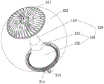
FIG. 10 is a schematic structural diagram of a lamp cap according to a third embodiment;
FIG. 11 is a cross-sectional view of FIG. 10;
fig. 12 is a partially enlarged view of fig. 11.
[ detailed description ] embodiments
In order to make the objects, technical solutions and advantages of the present invention more clearly understood, the present invention will be further described in detail with reference to the accompanying drawings and embodiments. It should be understood that the detailed description and specific examples, while indicating the invention, are given by way of illustration only, not by way of limitation. For those skilled in the art, without any creative effort, other embodiments obtained from the drawings and examples shall belong to the technical solution disclosed by the present invention.
Example one
As shown in fig. 1, 2, 3, 4, 5, 6, and 10, an electrical storage 120 includes an electrical storage main body 122 and an electrical storage cover 121 made of a non-metallic material (the non-metallic material is mainly any substance that does not have a shielding or reducing effect on electromagnetic waves and is not limited to the non-metallic material), the electrical storage cover 121 is disposed on the electrical storage main body 122, and a space formed by the electrical storage cover 121 (a space surrounded by the electrical storage cover 121 and the electrical storage main body 122) is communicated with a space formed by the electrical storage main body 122. The electrical appliance bin 120 is horn-shaped or hollow frustum-shaped as a whole; in use, the electrical compartment 120 is a semi-closed cavity with a downward opening. The electrical bin cover 121 is detachably connected with the electrical bin main body 122, and the connection part of the electrical bin cover 121 and the electrical bin main body 122 is connected in a smooth transition mode. A convex ring 1216 is arranged on the inner side of the lower end of the circumferential wall surface of the electrical bin cover 121, and a second annular groove 1225 is arranged on the upper end of the circumferential wall surface of the electrical bin main body 122; the collar 1216 mates with the second annular recess 1225. A waterproof mechanism 125 (shown in fig. 12) is further disposed at a joint of the electrical bin cover 121 and the electrical bin main body 122; in this embodiment, the waterproof mechanism 125 is an annular sealing ring with a U-shaped cross section; the heights of the two sides of the U-shaped sealing ring are unequal, and the height of the side far away from the axis of the sealing ring is lower, which is similar to an annular sealing ring with a J-shaped or hook-shaped cross section.
The electrical appliance bin cover 121 is in the shape of a trumpet or a section of a hollow frustum; the top end of the appliance compartment cover 121 forms a substantially closed top plane 1211, and an annular boss 1212 extends from the top plane 1211 along the axial direction of the appliance compartment cover 121. A waterproof vent valve mounting hole 1213, a line passing hole 1214 and a through hole 1215 are formed on the top plane 1211 positioned at the inner side of the annular boss 1212. The wire hole 1214 is matched with a waterproof screw (not shown) to allow the wire to pass through and is waterproof. The waterproof vent valve mounting hole 1213 is used for mounting a waterproof vent valve (not shown). The through hole 1215 is used for passing a connecting rod 236 installed and connected between the top cover and the electrical bin main body 122 when the electrical bin 120 is used in the lamp head (see fig. 11 and 12); the through hole 1215 may also be internally threaded to mate with external threads on the tie rod 236 or to mate with the tie rod 236 via a compression nut to secure the electrical cap 121.
The overall shape of the electrical bin main body 122 is also a section of a trumpet-shaped or hollow frustum; a second mounting and connecting mechanism 1221 is disposed at an end of the electrical cabinet main body 122 away from the electrical cabinet cover 121, and the second mounting and connecting mechanism 1221 is used for connecting the lamp holder 211 when the electrical cabinet 120 is used in a lamp cap. In this embodiment, the second mounting connection mechanism 1221 is a rim portion (if the electrical storage device main body 122 is a cap, the rim portion is like a brim) extending from the outer peripheral surface of the electrical storage device main body 122, and four radially protruding bosses 1222 are spaced apart from each other on the outermost wall surface of the rim portion, and are used for sliding guiding and engaging when the electrical storage device 120 is combined with the lamp holder 211 (as shown in fig. 11). Specifically, an arc-shaped rib 1223 is provided on the horizontal table surface at the lowermost portion of the rim portion near the outermost periphery of the rim portion and substantially perpendicular to the horizontal table surface of the rim portion, and a screw hole 1224 is provided on the arc-shaped rib 1223.
A plurality of mounting post holes 1228 are further formed in the inner wall of the electrical bin main body 122, and the mounting post holes 1228 are used for mounting a single lamp controller through a power supply mounting plate when the electrical bin 120 is used in a lamp holder; a driving power supply can be arranged in the electrical appliance bin 120 and can be arranged on the power supply mounting plate; i.e., the power mounting plate is mounted on the mounting post holes 1228.
One end of the electrical appliance bin main body 122 close to the electrical appliance bin cover 121 is hollowed out; one end of the electrical bin main body 122 close to the electrical bin cover 121 is provided with a connecting hole 1226 protruding out of the upper end surface of the electrical bin main body 122; the connecting hole 1226 extends axially along the electrical appliance bin main body 122 and is connected with the electrical appliance bin main body 122 through a connecting rib 1227, and the connecting ribs 1227 are hollowed out; when the electrical bin cover 121 and the electrical bin main body 122 are connected together, the electrical bin cover 121 extends into the electrical bin cover 121. Of course, the connection hole 1226 may also be disposed at a position of the electrical cabinet main body 122 close to the upper end surface of the electrical cabinet main body 122.
The electrical bin cover 121 and the electrical bin main body 122 are fixedly connected with each other through a connecting rod 236 (see fig. 11 and 12) in the using process. The electrical bin cover 121 and the electrical bin main body 122 can also be directly connected through bolts and nuts (or a double-threaded rod and other similar mechanisms) to form a whole body, so that the installation and the use are convenient; such as by a double threaded rod connected to threaded through hole 1215 and attachment hole 1226 as a unit.
Example two
As shown in fig. 7, 8, 9, 10 and 11, a light reflecting member 100 comprises a first member 110 and a second member 120, wherein the first member 110 is detachably connected with the second member 120; the first component 110 is in a hollow frustum shape or a horn shape, and the second component 120 is correspondingly in a hollow frustum shape or a horn shape. The second member 120 is joined to the first member 110 in a smooth transition such that the entire retroreflective member 100 is flared. The outer surface of the light reflecting part 100 is a light reflecting surface.
As shown in fig. 7, 8, 9, 10 and 11, an end (a smaller end of the first part 110) of the first part 110 far away from the second part 120 is provided with a relief hole 112 and a wire passing hole 111; a plurality of ribs 113 arranged in the circumferential direction are provided on the inner side of the bell-mouth edge of the end (the larger end of the first member) of the first member 110 which is in contact with the second member 120, and a step-shaped notch is formed in the circumferential direction on the inner wall surface of the port of the end of the first member 110 which is in contact with the second member 120, and the step-shaped notch and the ribs 113 form a first annular groove 114. Of course, the first component 110 and the second component 120 may also be engaged, such as by threads or other snap-fit arrangements.
The second component 120 in the second embodiment is the electrical cabin 120 in the first embodiment. Wherein, the first part 110 is connected with the second part 120, and actually, the first part 110 is connected with the electrical bin cover 121; namely, the first member 110 and the second member 120 are detachably connected to the annular boss 1212 on the appliance housing cover 121 through the first annular groove 114 on the first member 110.
It should be noted that, in fig. 11, there is a rod-shaped connecting rod 236, and the connecting rod 236 is a connecting mechanism for connecting the top cover and the electrical cabinet 120 when the light reflecting member 100 is used as a light head; the connecting rod 236 passes through the abdicating hole 112 and then is connected to the connecting hole 1226 of the electrical cabinet main body 122, and a lock nut may be disposed at an end of the first component 110 away from the electrical cabinet 120, so that the first component 110 and the electrical cabinet 120 are connected more tightly.
EXAMPLE III
As shown in fig. 10, 11 and 12, a lamp head includes a power supply 210, a lamp holder 211, a single lamp controller 212, and an integrally detachable light source module composed of a heat dissipation top cover 231, a light emitting assembly 232, a lamp housing 233, a connecting rod 236 and a light reflecting member 238; the light source module is detachably connected with the lamp holder 211 through a buckle by depending on the bottom end of the reflecting part 100; the power supply 210 is disposed in the lamp holder 211 through a power supply mounting plate in a space formed by the light reflecting member 238 and the lamp holder 211.
In this embodiment, the light reflecting member 238 is the light reflecting member 100 described in the second embodiment. The single lamp controller 212 is disposed in the second part 120 (i.e., the electrical cabinet body 122) of the light reflecting part 238 through a power supply mounting plate, so as to facilitate the control and management of the lamp head.
In this embodiment, the lamp holder 211 is substantially in the shape of a bowl with a bottom base (i.e. a spherical cap with a bottom base), and four sliding slots 213 with a closed end are formed on the lamp holder 211 and extend along the inner circumferential direction of the wall surface of the lamp holder 211. A screw hole 214 is formed at a position close to one of the sliding grooves 213 along the inner circumferential direction of the wall surface of the lamp holder; the screw hole 214 and the sliding groove 213 are close to the opening of the lamp holder 211.
The lamp holder 211 is further provided with a plurality of air holes to discharge hot air exhausted through the waterproof air vent valve in the cavity of the light source module, and meanwhile, the single lamp controller 212 can be controlled through electromagnetic waves.
The connecting rod 236 is a connecting mechanism for connecting the top cover and the electrical cabinet 120 when the light-reflecting component 100 is used as a lamp cap; the connecting rod 236 passes through the receding hole 112 and then is connected to the connecting hole 1226 of the electrical bin main body 122. A lock nut may be provided at an end of the first member 110 away from the electrical compartment 120 to allow a more secure connection between the first member 110 and the electrical compartment 120.
The boss 1222 on the electrical cabinet 120 in the light reflecting component 100 is correspondingly matched with the sliding groove 213; when the light source module 230 and the lamp holder 211 are assembled, the projection 1222 is close to the sliding groove 213, then the light source module is rotated to be matched with the sliding groove 213, and after the projection 1222 and the sliding groove 213 are correspondingly matched and clamped in place, the connection between the light source module 230 and the lamp holder 211 can be completed. However, in order to prevent the light source module 230 from rotating around the base 211, a fastening boss 215 having a screw hole 214 is further provided on the base 211, and the fastening boss 215 and the arc-shaped rib 1223 are further fastened by a screw.
After the lamp holder is installed in place, when the power supply 210 needs to be replaced and maintained, the light source module can be integrally detached from the lamp holder 211 only by detaching the screw and rotating the light source module relative to the lamp holder 211 by a certain angle; after the power supply 210 is replaced, the light source module is installed on the lamp holder 211 and fastened through screws, so that the connection between the light source module and the lamp holder 211 is completed; the whole dismounting and replacing maintenance work is simple and efficient.
Example four
The difference between this embodiment and the third embodiment is that, in this embodiment, the light reflecting component 238 and the electrical cabinet 120 are two independent components, the light reflecting component is sleeved outside the electrical cabinet 120, and the lower bottom edge of the light reflecting component abuts against the edge portion of the electrical cabinet main body 122.
EXAMPLE five
The present embodiment is different from the fourth embodiment in that the light reflecting member 238 is not present in the present embodiment. The connecting rod 236 is a connecting mechanism for connecting the heat dissipation top cover 231 and the electrical appliance bin 120; the connecting rod 236 is connected to the connecting hole 1226 of the electrical bin main body 122.
EXAMPLE six
A street lamp comprises a lamp post and at least one lamp cap directly or indirectly arranged on the lamp post, wherein the lamp cap is the third or fourth or fifth lamp cap of the embodiment.
By the above scheme, the utility model discloses will the electrical apparatus storehouse sets up to the electrical apparatus cang gai including electrical apparatus storehouse main part and non-metallic material, electrical apparatus cang gai set up in on the electrical apparatus storehouse main part, the space that the electrical apparatus cang gai formed with be linked together between the space that the electrical apparatus storehouse main part formed, the electromagnetic wave can transmit through the electrical apparatus cang gai externally, and the effectual reduction electrical apparatus storehouse improves the transmission quality of electromagnetic wave to the shielding that the electromagnetic wave formed and the negative effects who subducts. And simultaneously, because the electrical apparatus storehouse sets the user state opening semi-closed cavity down to for the light source module (by at least comprising top cap, luminous module, lamp shade and electrical apparatus storehouse) that uses the lamp holder of electrical apparatus storehouse forms a complete enclosure space, has improved the waterproof performance of light source module. In the space formed by the electrical appliance bin and the lamp holder, a single lamp controller is arranged for intelligent management of the lamp.
The embodiment just is the preferred embodiment of the utility model discloses an above-mentioned, the utility model discloses a protection scope not only limits in above-mentioned embodiment, and the all belongs to the utility model discloses a technical scheme under the thinking all belongs to the utility model discloses a technical scheme reveals, contains the utility model discloses within the scope of protection. As in addition to the above embodiments, the present invention has other modifications such as: the second mounting and connecting mechanism can be a simple mounting and positioning mechanism or can be positioned by directly utilizing the wall surface of the second part; or the lower end of the electrical appliance bin main body is not provided with a second mounting and positioning mechanism, and when the lamp holder is used in a lamp holder, the lamp holder is directly or indirectly connected to a lamp holder through a connecting rod (the connecting rod is in threaded connection with the electrical appliance bin cover and the electrical appliance bin main body), namely the connecting rod connects the heat-radiating lamp cover, the lamp shade, the electrical appliance bin and the lamp holder; or, in the lamp holder without the heat dissipation top cover, the lamp holder is directly or indirectly connected to the lamp holder through a connecting rod (the connecting rod is in threaded connection with the electrical bin cover and the electrical bin main body), namely the connecting rod connects the electrical bin and the lamp holder. Also, an external or internal thread or other type of first mounting connection mechanism (e.g., a fixed movable bolt) may be provided on the end of the first member 110 remote from the second member 120 to facilitate connection of the light reflecting member to the cover or light emitting assembly. The lamp cover and the lamp holder are connected by a connecting rod penetrating through the reflecting component, or the second component 120 is propped against the inner wall of the lamp shade through an installing and positioning mechanism, and the lamp holder is fixed on the lamp shade, so that the connecting rod is not required to be arranged.
It should be noted that, for those skilled in the art, various modifications and decorations can be made without departing from the principle of the present invention, and these modifications and decorations should be considered to be included in the protection scope of the present invention.
Claims (24)
1. The electric appliance bin is characterized by comprising an electric appliance bin main body and an electric appliance bin cover made of non-metal materials, wherein the electric appliance bin cover is arranged on the electric appliance bin main body, and a space formed by the electric appliance bin cover is communicated with a space formed by the electric appliance bin main body.
2. The appliance cartridge of claim 1, wherein the appliance cartridge cover is removably connected to the appliance cartridge body.
3. The appliance compartment of claim 1, wherein the connection between the lid and the main body is smooth.
4. The electrical cabinet according to claim 1, wherein a waterproof mechanism is disposed at a connection between the electrical cabinet cover and the electrical cabinet main body.
5. The electrical cabinet according to claim 4, wherein the waterproof mechanism is an annular sealing ring having a hook-like or U-shaped cross-section along the axial direction thereof.
6. The electrical equipment bin according to claim 1, wherein a convex ring is arranged on the inner side of the lower end of the circumferential wall surface of the electrical equipment bin cover, and a second annular groove is arranged on the upper end of the circumferential wall surface of the electrical equipment bin main body; the convex ring is matched with the second annular groove.
7. The electrical cabinet according to any of claims 1 to 6, wherein the top of the electrical cabinet cover is closed or semi-closed.
8. The electrical cabinet according to any of claims 1 to 6, wherein the top of the electrical cabinet cover forms a closed plane or a semi-closed plane.
9. The electrical cabinet according to any of claims 1 to 6, characterized in that the top of the electrical cabinet cover is provided with through holes and/or blind holes.
10. The electrical cabinet according to any one of claims 1 to 6, wherein the top of the electrical cabinet cover is provided with waterproof vent valve mounting holes and/or wire passing holes.
11. The electrical cabinet according to any of claims 1 to 6, wherein the top of the electrical cabinet cover is provided with an annular boss.
12. The electrical cabinet according to any one of claims 1 to 6, wherein one end of the electrical cabinet main body close to the electrical cabinet cover is hollowed out.
13. The electrical cabinet according to any one of claims 1 to 6, wherein a connecting hole is formed at one end of the electrical cabinet main body close to the electrical cabinet cover.
14. The appliance cartridge of claim 13, wherein the attachment hole extends axially along the appliance cartridge body and extends into the appliance cartridge cover when the appliance cartridge cover is coupled to the appliance cartridge body.
15. A reflective component comprises a first component and a second component, wherein the first component is detachably connected with the second component; the second component is the electrical compartment of any one of claims 1 to 14.
16. A retroreflective article according to claim 15, wherein said first element is frustoconical or flared and said second element is correspondingly frustoconical or flared.
17. A retroreflective element according to any one of claims 15 or 16, wherein said second element meets said first element at a smooth transition where said second element meets said first element.
18. The reflective member of any one of claims 15 or 16, wherein the first member and the second member are removably connected to the annular projection on the appliance compartment cover via a first annular groove on the first member.
19. The reflective member as claimed in claim 18, wherein the first annular groove is formed by a plurality of ribs circumferentially disposed inside the edge of the port at the end of the first member connected to the cover of the electrical cabinet, and a step-shaped notch circumferentially formed on the inner wall surface of the port at the end of the first member connected to the cover of the electrical cabinet.
20. A lamp cap comprising a lamp holder, a light emitting module, a top cover, a lamp shade, and a reflective member according to any one of claims 15 to 19.
21. The light head of claim 20, further comprising a connecting rod fixedly connected between the top cover and the electrical cabinet body through the first member.
22. A lamp holder, comprising a lamp holder, a light-emitting module, a top cover, a lampshade, and characterized by further comprising an electrical cabinet, wherein the electrical cabinet is the electrical cabinet in any one of claims 1 to 14.
23. The light head of claim 22, further comprising a connecting rod fixedly connected between the top cover and the electrical cabinet body.
24. A street light comprising a light pole and at least one head mounted directly or indirectly on the light pole, wherein the head is as claimed in any one of claims 20 to 23.
Priority Applications (1)
| Application Number | Priority Date | Filing Date | Title |
|---|---|---|---|
| CN201921357405.5U CN210662586U (en) | 2019-08-20 | 2019-08-20 | Electrical equipment bin and light reflecting component, lamp holder and street lamp using electrical equipment bin |
Applications Claiming Priority (1)
| Application Number | Priority Date | Filing Date | Title |
|---|---|---|---|
| CN201921357405.5U CN210662586U (en) | 2019-08-20 | 2019-08-20 | Electrical equipment bin and light reflecting component, lamp holder and street lamp using electrical equipment bin |
Publications (1)
| Publication Number | Publication Date |
|---|---|
| CN210662586U true CN210662586U (en) | 2020-06-02 |
Family
ID=70809358
Family Applications (1)
| Application Number | Title | Priority Date | Filing Date |
|---|---|---|---|
| CN201921357405.5U Active CN210662586U (en) | 2019-08-20 | 2019-08-20 | Electrical equipment bin and light reflecting component, lamp holder and street lamp using electrical equipment bin |
Country Status (1)
| Country | Link |
|---|---|
| CN (1) | CN210662586U (en) |
Cited By (1)
| Publication number | Priority date | Publication date | Assignee | Title |
|---|---|---|---|---|
| CN110440202A (en) * | 2019-08-20 | 2019-11-12 | 珠海金晟照明科技有限公司 | Electrical store and reflecting part, lamp cap and the street lamp for using the electrical store |
-
2019
- 2019-08-20 CN CN201921357405.5U patent/CN210662586U/en active Active
Cited By (1)
| Publication number | Priority date | Publication date | Assignee | Title |
|---|---|---|---|---|
| CN110440202A (en) * | 2019-08-20 | 2019-11-12 | 珠海金晟照明科技有限公司 | Electrical store and reflecting part, lamp cap and the street lamp for using the electrical store |
Similar Documents
| Publication | Publication Date | Title |
|---|---|---|
| CN210662586U (en) | Electrical equipment bin and light reflecting component, lamp holder and street lamp using electrical equipment bin | |
| CN105508920A (en) | LED table lamp | |
| CN105546414A (en) | Aluminum plastic LED (Light Emitting Diode) flood lamp | |
| CN208442740U (en) | A kind of solar street light convenient for battery roll | |
| CN101684910A (en) | Combined recessed lamp without light cylinder | |
| CN211176538U (en) | Lamp holder and street lamp using same | |
| CN201326956Y (en) | Lampshade-free combined-type recessed-light | |
| CN210319854U (en) | Reflecting part and lamp holder and street lamp using same | |
| CN102141200A (en) | High-power LED (light emitting diode) light fitting | |
| CN210345124U (en) | LED (light emitting diode) surface-mounted down lamp structure | |
| CN201293244Y (en) | High power wall washing lamp | |
| CN210035263U (en) | Reflecting component, lamp holder using same and street lamp | |
| CN211176417U (en) | Sealing ring, lamp holder and street lamp using lamp holder | |
| CN110440202A (en) | Electrical store and reflecting part, lamp cap and the street lamp for using the electrical store | |
| CN214064663U (en) | Lamp holder and lamp holder and street lamp using same | |
| CN209012957U (en) | A kind of adjustable lamps and lanterns | |
| CN206803019U (en) | A kind of lampshade of ceiling lamp | |
| CN210462734U (en) | Adjustable down lamp | |
| CN108730929B (en) | Outdoor lamp stand of many connected functions | |
| CN110848618A (en) | Lamp holder and street lamp using same | |
| CN202835041U (en) | Light-Emitting Diode (LED) lamp | |
| CN102141224A (en) | Embedded ceiling lamp | |
| CN206176068U (en) | Integral type LED soft light | |
| CN214948821U (en) | Mining lamp for food processing place | |
| WO2018161667A1 (en) | Aluminium substrate and drive power supply box mounting structure for led lamp |
Legal Events
| Date | Code | Title | Description |
|---|---|---|---|
| GR01 | Patent grant | ||
| GR01 | Patent grant |