CN210634065U - Novel lens mouth of a river excision device - Google Patents
Novel lens mouth of a river excision device Download PDFInfo
- Publication number
- CN210634065U CN210634065U CN201921349903.5U CN201921349903U CN210634065U CN 210634065 U CN210634065 U CN 210634065U CN 201921349903 U CN201921349903 U CN 201921349903U CN 210634065 U CN210634065 U CN 210634065U
- Authority
- CN
- China
- Prior art keywords
- lens
- rotating
- cutting device
- annular turntable
- placing
- Prior art date
- Legal status (The legal status is an assumption and is not a legal conclusion. Google has not performed a legal analysis and makes no representation as to the accuracy of the status listed.)
- Active
Links
Images

Abstract
The utility model discloses a novel lens mouth of a river excision device, including workstation and rotation anchor clamps, rotate anchor clamps and locate workstation top surface middle part, still be equipped with on the workstation: the laser cutting device is used for cutting the water gap of the lens and arranged on the outer side of one end of the rotating clamp; and the manipulator A is used for sequentially clamping and placing the lenses with the cut water gaps, and is arranged on the outer side of the other end of the rotary clamp. The utility model discloses a cooperation of rotating anchor clamps, laser cutting device and manipulator A can be amputated the lens mouth of a river fast, has greatly improved the production efficiency of enterprise, has reduced the manpower loss, has reduced the manufacturing cost of enterprise.
Description
Technical Field
The utility model relates to a mouth of a river resection device especially relates to a novel lens mouth of a river resection device.
Background
After the lens is subjected to injection molding, forming a net-disc-like injection molding piece, wherein the injection molding piece comprises a trunk and branches, and the lens is positioned at the tail ends of the branches; in the production and processing process of the lens, a water gap of the produced lens is often required to be cut, the cut lens product is orderly placed on a material rack, and then the lens is further processed; at present, the water gap is cut off slowly in the production process of the lens, but the working efficiency of a plurality of devices for cutting off the water gap of the lens is low due to the integral structural design of the devices, and the devices need to be improved to meet the production requirement.
SUMMERY OF THE UTILITY MODEL
The to-be-solved technical problem of the utility model is to overcome prior art not enough, provide a novel lens mouth of a river excision device.
In order to solve the technical problem, the utility model provides a technical scheme does:
the utility model provides a novel lens mouth of a river excision device, includes workstation and rotating jig, rotating jig locates workstation top surface middle part, still be equipped with on the workstation:
the laser cutting device is used for cutting a water gap of the lens and arranged on the outer side of one end of the rotating clamp;
and the manipulator A is used for sequentially clamping and placing the lenses with the cut water gaps, and is arranged on the outer side of the other end of the rotary clamp.
The utility model discloses in, preferably, still include manipulator B for snatch uncut product and remove the lens mouth of a river waste material that has cut.
In the utility model, preferably, the rotating fixture comprises a rotating plate, rotating assemblies are arranged at two ends of the top of the rotating plate, each rotating assembly comprises a plurality of placing seats, and the placing seats are connected with the rotating plate through a rotating shaft A; the rotating assembly further comprises an annular turntable for driving the placing seat to rotate, the placing seat is arranged above the annular turntable along the circumference of the annular turntable, and one end of the placing seat is connected with the annular turntable;
the first driving device is used for driving the annular turntable to rotate, and then the placing seat is driven to rotate.
The utility model discloses in, preferably, one of the seat of settling serves and is equipped with a slot hole, the annular carousel upwards is equipped with and runs through the pin of slot hole, the annular carousel passes through the pin with the seat of settling is connected.
The utility model discloses in, preferably, first drive arrangement is first telescoping cylinder, the one end of first telescoping cylinder with it is articulated to change the board, the other end of telescoping cylinder is equipped with the telescopic link, the telescopic link of first telescoping cylinder with the annular turntable is articulated.
The utility model discloses in, preferably, still include and be used for the restriction annular carousel pivoted restricting means.
The utility model discloses in, preferably, the runner assembly includes six arrangement seats, the arrangement seat equipartition is located annular carousel top.
The utility model discloses in, preferably, it is equipped with pivot B to change board bottom surface middle part downwardly connected, be equipped with the drive in the workstation pivot B pivoted second drive arrangement.
The utility model discloses in, preferably, second drive arrangement is the second telescoping cylinder, pivot B lower part is equipped with the gear, the telescopic link of second telescoping cylinder passes through the rack drive gear revolve.
The utility model discloses in, preferably, be equipped with an opening on the workstation top surface, the workstation side is equipped with an export, the opening with the export is through a access connection, the passageway is located in the workstation.
Compared with the prior art, the utility model has the advantages that the rotary fixture is arranged, the lens component can be arranged on the rotary fixture before the water gap is cut, and the rotary fixture can rotate the lens component arranged on the rotary fixture to a preset position; the utility model discloses a lens mouth of a river resection device, laser cutting device locate the one end outside of rotating fixture, manipulator A locates the other end outside of rotating fixture, rotate through rotating fixture and make the lens subassembly that one end did not cut on the rotating fixture be in laser cutting device one side, and the lens subassembly that the other end has cut the mouth of a river through laser cutting device on the rotating fixture is in manipulator A this side, snatch and put each lens through manipulator A; in the utility model, due to the injection molding, the inserted bar (used for inserting into the inserting hole of the lens placing jig to fix the lens) on each lens is not towards the outside, so that the mechanical arm A is inconvenient to clamp and insert, and the utility model also solves the problem by rotating the clamp to rotate the whole lens assembly by a certain angle; the utility model discloses greatly improve the production efficiency of enterprise, reduced the manpower loss, reduced the manufacturing cost of enterprise.
Drawings
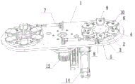
FIG. 1 is a schematic view of the overall structure of the lens nozzle cutting device of the present invention;
FIG. 2 is a schematic view of the overall structure of the rotary clamp of the present invention;
illustration of the drawings: 1-rotating plate, 2-fixed frame, 3-annular rotating disc, 4-placing seat, 5-rotating shaft A, 6-long hole, 7-first telescopic cylinder, 8-limiting device, 9-sucker component, 10-limiting block, 11-workbench, 12-rotating shaft B, 13-manipulator A, 14-second telescopic cylinder, 15-laser generating device, 16-laser head, 17-X direction guide rail, 18-Y direction guide rail, 19-support, 20-lens placing jig and 21-through hole.
Detailed Description
In order to facilitate understanding of the present invention, the present invention will be described more fully and specifically with reference to the preferred embodiments, but the scope of the present invention is not limited to the specific embodiments described below.
It should be particularly noted that when an element is referred to as being "fixed to, connected to or communicated with" another element, it can be directly fixed to, connected to or communicated with the other element or indirectly fixed to, connected to or communicated with the other element through other intermediate connecting components.
Unless otherwise defined, all terms of art used hereinafter have the same meaning as commonly understood by one of ordinary skill in the art. The terminology used herein is for the purpose of describing particular embodiments only and is not intended to limit the scope of the present invention.
Examples
As shown in fig. 1 and 2
The embodiment of the utility model discloses a novel lens mouth of a river resection device, the embodiment of the utility model provides a rotating clamp for placing the lens subassembly and rotating, can also make the lens subassembly placed on it rotate predetermined angle wholly, rotating clamp includes commentaries on classics board 1, the top both ends of commentaries on classics board 1 all are equipped with rotating assembly, rotating assembly includes a plurality of arrangement seats 4, arrangement seats 4 are connected with commentaries on classics board 1 through pivot A5; the rotating assembly further comprises an annular turntable 3 for driving the placing seat 4 to rotate, the placing seat 4 is arranged above the annular turntable 3 along the circumference of the annular turntable 3, and one end of the placing seat 4 is connected with the annular turntable 3;
the device also comprises a first driving device which is used for driving the annular turntable 3 to rotate so as to drive the placing seat 4 to rotate.
In the embodiment, specifically, a long hole 6 is arranged at one end of the placing seat 4, a pin penetrating through the long hole 6 is upwards arranged on the annular turntable 3, and the annular turntable 3 is connected with the placing seat 4 through the pin; when the annular turntable type automatic transmission device works, the annular turntable 3 is driven to rotate through the first driving device, and the annular turntable 3 drives the placing seat 4 arranged above the annular turntable 3 to rotate through the pin (the placing seat 4 rotates around the rotating shaft A5); it should be noted that, in this embodiment, it may also be: the long hole 6 is arranged at the top of the annular turntable 3, the pin is arranged at the bottom of the placing seat 4, and the same effect can be realized through the matching of the long hole 6 and the pin; further, the present embodiment may also be: the placing seat 4 is connected with the annular rotary table 3 through a connecting rod which is hinged with the annular rotary table 3, and the annular rotary table 3 drives the placing seat 4 to rotate through the connecting rod; further, the present embodiment may also be: the bottom of the placing seat 4 extends downwards to form threads, threads matched with the bottom of the placing seat 4 are arranged on the circumference of the inner side of the annular turntable 3, and the annular turntable 3 can drive the placing seat 4 to rotate through threaded connection.
Preferably, in this embodiment, the rotating plate 1 is provided with a fixing frame 2, the seat 4 is connected to the fixing frame 2 through a rotating shaft a5, the seat 4 is disposed above the fixing frame 2, and the fixing frame 2 is disposed inside the annular rotating disc 3.
In this embodiment, first drive arrangement is first telescoping cylinder 7, and the one end of first telescoping cylinder 7 is articulated with commentaries on classics board 1, and the other end of telescoping cylinder is equipped with the telescopic link, and the telescopic link of first telescoping cylinder 7 is articulated with annular turntable 3, and through the rotation of first telescopic link drive annular turntable 3, and then drive and place seat 4 and rotate. Of course, the ring-shaped rotating disk 3 can also be driven to rotate by a motor.
The embodiment further comprises a limiting device 8 for limiting the first driving device to drive the annular turntable 3 to rotate, and the limiting device 8 is arranged on the outer side of the annular turntable 3. Limiting device 8 is located on changeing board 1 through the fixed block, is equipped with the gag lever post that can adjust length on the limiting device 8, through the distance of the telescopic link of adjustment gag lever post and first telescoping cylinder 7, and then can restrict the driving distance of the telescopic link of first telescoping cylinder 7 to the first telescoping cylinder 7 accurate drive lens that makes that can be better rotates.
Preferably, the rotating assembly comprises six placing seats 4, and the placing seats 4 are uniformly distributed above the annular rotating disc 3.
In this embodiment, the placing base 4 is provided with a suction cup assembly 9. The periphery of the placing seat 4 is provided with a limiting block 10. The sucking disc assembly 9 can better fix the lens, specifically, the placing seat 4 is provided with a sucking disc, the middle part of the sucking disc is provided with an air hole, the sucking disc assembly 9 is controlled to fix the lens through air, and the lens can be temporarily fixed when the air hole sucks air; the periphery of the placing seat 4 is provided with a limiting block 10 for limiting the lens.
In this embodiment, the rotating plate 1 is provided with a connecting plate, one end of the first telescopic cylinder 7 is hinged to the connecting plate, and the telescopic rod of the first telescopic cylinder 7 is hinged to the annular rotating disc 3 through a connecting piece.
The utility model relates to a novel lens nozzle cutting device with a rotary clamp, which comprises the rotary clamp; the rotary fixture is arranged in the middle of the top surface of the workbench 11, the middle of the bottom surface of the rotary plate 1 is downwards connected with a rotating shaft B12, and a second driving device for driving the rotating shaft B12 to rotate is arranged in the workbench 11; the workbench 11 is also provided with:
the laser cutting device is used for cutting a water gap of the lens and is arranged on the outer side of one end of the rotating plate 1;
the manipulator A13 is used for sequentially clamping and placing the lenses with the cut water gaps, and the manipulator A13 is arranged on the outer side of the other end of the rotating plate 1;
and a manipulator B (not shown in the figure) for grabbing uncut products and removing the cut lens nozzle scraps.
In the utility model, the uncut lens assembly is grabbed by the manipulator B and placed on the rotating clamp, the rotating assemblies are arranged at the two ends of the top of the rotating plate 1, and the rotating assemblies at the two ends are exchanged by rotation; the design is that the rotary plate 1 rotates to enable the lens assembly with one end not cut on the rotary plate 1 to be positioned on one side of a laser cutting device, the water gap of the lens assembly is cut through the laser cutting device, the end, which is used for cutting the water gap, on the rotary plate 1 is positioned on one side of a manipulator A13 through the rotation of the rotary plate 1, the other end is positioned on one side of the laser cutting device at the moment, and the uncut lens assembly is grabbed and placed through a manipulator B; the rotating plate 1 in this embodiment rotates, specifically, the middle of the bottom surface of the rotating plate 1 is connected downwards to be provided with a rotating shaft B12, and a second driving device for driving the rotating shaft B12 to rotate is arranged in the workbench 11; the rotating plate 1 is driven to rotate by a second driving device; the embodiment further comprises a control device, the control device is a PLC control device, the working table 11, the rotating clamp, the first driving device, the second driving device, the laser cutting device, the manipulator A13, the manipulator B and other embodiments of structures are all connected with the PLC control device, and the PLC controls all the structures to work orderly.
In the embodiment of the present invention, due to the reason of injection molding, that is, in order to improve the injection molding quality of the lenses, the insertion rod (for inserting into the insertion hole of the lens placing jig 20 to fix the lenses) on each lens is not along the diameter of the annular turntable 3 and faces outward, so that it is not convenient for the manipulator a13 to insert and clamp, therefore the present invention solves the problem by rotating the lens assembly integrally by a certain angle through the annular turntable 3, the placing seat 4 and the first driving device so that the insertion rod on the lens faces outward along the diameter of the annular turntable 3; when the specific lens subassembly was placed on rotating assembly, the lens quantity on the lens subassembly was matchd with mount 4, and the lens correspondence of each lens was settled on corresponding mount 4, and when the mouth of a river of lens subassembly was cut, rotated through first drive arrangement drive annular carousel 3, rotated through pin drive mount 4, and then drive each lens and rotate to same direction, realized wholly rotating, made the lens subassembly of cutting be convenient for manipulator A13 clamp get and put.
The utility model discloses one of them preferred embodiment does, and second drive arrangement is second telescoping cylinder 14, and second telescoping cylinder 14 is pneumatic telescoping cylinder, and pivot B12 lower part is equipped with the gear, and the telescopic link of second telescoping cylinder 14 passes through rack drive gear and rotates. The utility model discloses in, second drive arrangement also can be the motor, rotates through motor drive pivot B12, and then control commentaries on classics board 1 rotates.
In the embodiment of the utility model, the laser cutting device comprises a laser generating device 15, a laser head 16 for cutting the water gap of the lens, an X-direction guide rail 17, a Y-direction guide rail 18 and a third driving device for driving the laser head 16 to move to a designated position; the laser generating device 15 is arranged at one end of the top surface of the workbench 11, a pair of parallel X-direction guide rails 17 are arranged at one end of the top surface of the workbench 11 and extend towards the middle of the top surface of the workbench 11, the Y-direction guide rails 18 are perpendicular to the X-direction guide rails 17 and are arranged on the X-direction guide rails 17, and the laser head 16 is arranged on the Y-direction guide rails 18 through sliders. Specifically, third drive arrangement includes motor A and motor B, is equipped with lead screw A on the X direction guide rail 17, and motor A's pivot is passed through the shaft coupling and is connected with lead screw A, and X direction guide rail 17 is located through the connecting block at Y direction guide rail 18 both ends, all is equipped with the screw-nut A who is connected with screw-nut A in the connecting block, realizes that Y direction guide rail 18 moves on X direction guide rail 17 under motor A's drive, the utility model discloses in, be equipped with lead screw B on the Y top guide rail, motor B's pivot is passed through the shaft coupling and is connected with screw-nut B, and the slider passes through screw-nut B and is connected with screw-nut B, realizes under motor B's drive that the slider moves on Y direction guide rail 18 to realize that laser head 16 can move in X or Y direction, realize that laser head 16 can carry out the fly-cutting to the.
The embodiment of the utility model provides an in another kind of scheme laser generator 15, replace above-mentioned X direction guide rail 17 and Y direction guide rail 18 for X direction hold-in range and Y direction hold-in range respectively, X direction hold-in range and Y direction hold-in range are all located on the mounting bracket, motor A and motor B are step motor, motor A drives synchronous pulley A and then drives X direction hold-in range work through the drive, Y direction hold-in range locates on X direction hold-in range through the mounting bracket, motor B drives synchronous pulley B and then drives Y direction hold-in range work, it moves on Y direction guide rail 18 to realize the slider under motor B's drive, thereby realize that laser head 16 can move in X or Y direction, realize that laser head 16 can carry out the fly-cutting to the mouth of a river of each lens on the lens subassembly. The utility model discloses preferably be X direction hold-in range and Y direction hold-in range, the reason is that hold-in range work efficiency is fast and can accurate drive the mouth of a river of laser head 16 to each lens on the appointed position pair lens subassembly and carry out the fly-cutting.
The utility model discloses in, the tool 20 is put to the support 19 and lens to the 11 top surface other end of workstation, and manipulator A13 sets firmly on support 19, and in this embodiment, manipulator A13 is six manipulators, can realize pressing from both sides the lens on the lens subassembly that has cut off and get and put on lens are put tool 20, the utility model discloses still include manipulator C (not shown in the figure), manipulator C locates on the workstation 11 or the outside, and manipulator C is used for putting and presss from both sides and get lens and put tool 20, and 11 top surface other end both sides of this embodiment all are equipped with lens and put tool 20, and when tool 20 is put to the lens of one side fills up, remove it through manipulator C to put tool 20 transport to this position with empty lens on, manipulator A13 can put tool 20 to the lens of opposite side and put the lens and not delay work.
The utility model discloses one of them preferred embodiment does, is equipped with an opening 21 on the 11 top surfaces of workstation, and 11 sides of workstation are equipped with an export, and opening 21 is connected through a passageway with the export, and the workstation 11 inboards is located to the passageway. Concrete in this embodiment, when the mouth of a river of lens subassembly was cut to the laser cutting device, manipulator B placed lens mouth of a river waste material in opening 21 this moment, through export discharge after the passageway, and this embodiment manipulator B locates on workstation 11 or the outside, and manipulator B shifts away lens mouth of a river waste material back commentaries on classics board 1 just rotates from not influencing manipulator A13's follow-up the clamp of getting to the lens and get.
Compared with the prior art, the embodiment has the advantages that: the device is provided with a rotating clamp, the lens assembly can be arranged on the rotating clamp before the water gap is cut, a placing seat is used for placing a lens, and the rotating clamp can rotate the lens assembly placed on the rotating clamp to a preset position; the utility model discloses a lens mouth of a river resection device, laser cutting device locate the one end outside of commentaries on classics board, manipulator A locates the other end outside of commentaries on classics board, places uncut lens subassembly on to the rotating fixture through manipulator B, rotates through the commentaries on classics board and makes the uncut lens subassembly of one end on the commentaries on classics board be in laser cutting device one side, and the lens subassembly that the other end has cut the mouth of a river through laser cutting device on the commentaries on classics board is in manipulator A this side, snatchs and puts each lens through manipulator A; in the utility model, due to the injection molding, the inserted bar (used for being inserted into the insertion hole of the lens placing jig to fix the lens) on each lens does not face outwards along the diameter of the annular turntable, so that the mechanical arm A is inconvenient to clamp and insert, and the utility model solves the problem by rotating the whole lens assembly by a certain angle through the annular turntable, the placing seat and the first driving device to enable the inserted bar on the lens to face outwards along the diameter of the annular turntable; this embodiment has greatly improved the production efficiency of enterprise, has reduced the manpower loss, has reduced the manufacturing cost of enterprise.
Claims (10)
1. The utility model provides a novel lens mouth of a river excision device which characterized in that: including workstation and rotation anchor clamps, it locates to rotate anchor clamps workstation top surface middle part, still be equipped with on the workstation:
the laser cutting device is used for cutting a water gap of the lens and arranged on the outer side of one end of the rotating clamp;
and the manipulator A is used for sequentially clamping and placing the lenses with the cut water gaps, and is arranged on the outer side of the other end of the rotary clamp.
2. The novel lens nozzle cutting device according to claim 1, characterized in that: the automatic lens cutting machine further comprises a manipulator B for grabbing uncut products and removing cut lens nozzle waste.
3. The novel lens nozzle cutting device according to claim 1, characterized in that: the rotating clamp comprises a rotating plate, rotating assemblies are arranged at two ends of the top of the rotating plate respectively, each rotating assembly comprises a plurality of placing seats, and the placing seats are connected with the rotating plate through rotating shafts A; the rotating assembly further comprises an annular turntable for driving the placing seat to rotate, the placing seat is arranged above the annular turntable along the circumference of the annular turntable, and one end of the placing seat is connected with the annular turntable;
the first driving device is used for driving the annular turntable to rotate, and then the placing seat is driven to rotate.
4. The novel lens nozzle cutting device according to claim 3, characterized in that: one end of the placing seat is provided with a long hole, the annular turntable is upwards provided with a pin penetrating through the long hole, and the annular turntable is connected with the placing seat through the pin.
5. The novel lens nozzle cutting device according to claim 3, characterized in that: the first driving device is a first telescopic cylinder, one end of the first telescopic cylinder is hinged to the rotating plate, a telescopic rod is arranged at the other end of the telescopic cylinder, and the telescopic rod of the first telescopic cylinder is hinged to the annular rotary table.
6. The novel lens nozzle cutting device according to claim 3 or 5, characterized in that: the annular turntable is characterized by also comprising a limiting device for limiting the rotation of the annular turntable.
7. The novel lens nozzle cutting device according to claim 3, characterized in that: the rotating assembly comprises six placing seats, and the placing seats are uniformly distributed above the annular turntable.
8. The novel lens nozzle cutting device according to claim 3, characterized in that: the middle part of the bottom surface of the rotating plate is downwards connected with a rotating shaft B, and a second driving device for driving the rotating shaft B to rotate is arranged in the workbench.
9. The novel lens nozzle cutting device according to claim 8, characterized in that: the second driving device is a second telescopic cylinder, a gear is arranged on the lower portion of the rotating shaft B, and a telescopic rod of the second telescopic cylinder drives the gear to rotate through a rack.
10. A novel lens nozzle cutting device according to claim 1 or 2, characterized in that: the top surface of the workbench is provided with an opening, the side surface of the workbench is provided with an outlet, the opening is connected with the outlet through a channel, and the channel is arranged in the workbench.
Priority Applications (1)
| Application Number | Priority Date | Filing Date | Title |
|---|---|---|---|
| CN201921349903.5U CN210634065U (en) | 2019-08-19 | 2019-08-19 | Novel lens mouth of a river excision device |
Applications Claiming Priority (1)
| Application Number | Priority Date | Filing Date | Title |
|---|---|---|---|
| CN201921349903.5U CN210634065U (en) | 2019-08-19 | 2019-08-19 | Novel lens mouth of a river excision device |
Publications (1)
| Publication Number | Publication Date |
|---|---|
| CN210634065U true CN210634065U (en) | 2020-05-29 |
Family
ID=70790635
Family Applications (1)
| Application Number | Title | Priority Date | Filing Date |
|---|---|---|---|
| CN201921349903.5U Active CN210634065U (en) | 2019-08-19 | 2019-08-19 | Novel lens mouth of a river excision device |
Country Status (1)
| Country | Link |
|---|---|
| CN (1) | CN210634065U (en) |
-
2019
- 2019-08-19 CN CN201921349903.5U patent/CN210634065U/en active Active
Similar Documents
| Publication | Publication Date | Title |
|---|---|---|
| CN107030530B (en) | Full-automatic multi-station multi-axis numerical control CNC machining center and machining method | |
| CN108512377B (en) | Three-wire parallel winding block stator winding machine | |
| CN107855781B (en) | Automatic resistance welding equipment | |
| CN110883595B (en) | Machining is with deciding clamping apparatus | |
| CN210634064U (en) | Rotating clamp and lens water gap cutting device with same | |
| CN217371215U (en) | Automatic hardware assembling equipment | |
| CN208895487U (en) | Pipe fitting group is to equipment | |
| CN210634065U (en) | Novel lens mouth of a river excision device | |
| CN109849290A (en) | The moulding mouth of a river based on small-sized machine arm automates excision equipment | |
| KR0182278B1 (en) | Bead removing device for pallette made of synthetic resin and bead cutter mechanism using the same | |
| CN210435373U (en) | PE tee bend pipe fitting terminal surface processing equipment | |
| CN210818281U (en) | Automatic unloading mechanism of going up of ring gear | |
| CN113118522B (en) | Automatic milling thimble seal equipment | |
| CN210546032U (en) | High-precision full-automatic dispensing and curing equipment suitable for vehicle-mounted lens | |
| CN208019529U (en) | A kind of peeler | |
| CN220296420U (en) | Quick clamping jig | |
| CN110303196A (en) | A kind of axle shell both ends cutting robot and its cutting method | |
| CN104440091A (en) | Three-in-one punching and milling machine for adapter | |
| CN215092159U (en) | Milling machine fixture for machining auto-parts mould | |
| CN213080271U (en) | Sawing machine applied to welding tool manufacturing system | |
| CN115846731B (en) | Intelligent numerical control platform convenient for fixing and processing thin-wall parts | |
| CN219004716U (en) | Positioning fixture for milling machine | |
| CN215468523U (en) | Metal band sawing machine convenient to location | |
| CN216913150U (en) | Blade grinding machine | |
| CN219731692U (en) | Pier stud stirrup positioning processing rack |
Legal Events
| Date | Code | Title | Description |
|---|---|---|---|
| GR01 | Patent grant | ||
| GR01 | Patent grant |