CN210632677U - Steel wire surface drawing dust cleaning device - Google Patents
Steel wire surface drawing dust cleaning device Download PDFInfo
- Publication number
- CN210632677U CN210632677U CN201921029269.7U CN201921029269U CN210632677U CN 210632677 U CN210632677 U CN 210632677U CN 201921029269 U CN201921029269 U CN 201921029269U CN 210632677 U CN210632677 U CN 210632677U
- Authority
- CN
- China
- Prior art keywords
- steel wire
- cleaning device
- platform
- fixedly connected
- support
- Prior art date
- Legal status (The legal status is an assumption and is not a legal conclusion. Google has not performed a legal analysis and makes no representation as to the accuracy of the status listed.)
- Active
Links
Images


Abstract
A steel wire surface drawing dust cleaning device comprises a drawing platform, the upper surface of the drawing platform is fixedly connected with a steel wire drawing machine, a steel wire is drawn out from the output end of the steel wire drawing machine, the upper surface of the drawing platform on the right side of the steel wire drawing machine is fixedly connected with a gantry support, the upper surface of the gantry support is provided with a cleaning mechanism, the upper surface of the drawing platform is provided with a water storage tank, the bottom of the water storage tank is fixedly communicated with a drain pipe, the upper surface of the drawing platform on the right side of the gantry support is fixedly connected with a water removal mechanism, the lower end of the drawing platform, the warm water is used for washing the steel wire through the arranged spray head, the drawing dust on the surface of the steel wire is washed away, then scrape the steel wire through the doctor-bar, the doctor-bar of rubber material strikes off steel wire surface adnexed water and drawing dust, and then makes the steel wire surface keep clean, prevents to cause the influence to the qualification rate of product.
Description
Technical Field
The utility model relates to a steel wire draws the field, concretely relates to dust cleaning device is drawn on steel wire surface.
Background
Along with the market competition of low tin bronze plated tire bead wire rope products, the requirement of users on the adhesive property of the tire bead wire rope and rubber is higher and higher, the cleaning treatment of the surface of the reinforced wire rope is more favorable for improving the product performance of the tire bead wire rope, in the production process, dirt such as drawing powder lubricant and the like used in the drawing process is attached to the surface of the wire rope before plating, and the dirt remains on the wire rope after the wire rope is sintered before tempering and is not favorable for subsequent cleaning of the surface of the wire rope, so that the coating composition on the surface of the wire rope is influenced to influence the adhesive property of the. The cleaning effect of the cleaning device for the dust drawn on the surface of the existing steel wire rope is poor, a lot of dust can still be remained on the surface of the steel wire rope, the qualification rate of products is influenced, and therefore the cleaning device for the dust drawn on the surface of the steel wire rope is required to be designed for completion.
SUMMERY OF THE UTILITY MODEL
The to-be-solved technical problem of the utility model is to provide a dust cleaning device is drawn on steel wire surface, make it can be with drawing dust clean up of steel wire surface.
The utility model provides a technical scheme that technical problem adopted is: the utility model provides a dust cleaning device is drawn on steel wire surface, includes draws the platform, the last fixed surface of drawing the platform is connected with the steel wire drawbench, the steel wire is extracted to the output of steel wire drawbench, draw the platform and be located the last fixed surface on steel wire drawbench right side and be connected with gantry support, gantry support's upper surface is equipped with clearance mechanism, the aqua storage tank has been seted up to the upper surface of drawing the platform, the fixed intercommunication in bottom of aqua storage tank has the drain pipe, draw the platform and be located the last fixed surface on gantry support right side and be connected with water removal mechanism, draw the lower extreme fixedly connected with support frame of platform.
As the utility model discloses a preferred technical scheme, clearance mechanism includes the warm water tank, warm water tank fixed connection is on portal jib support's upper surface, portal jib support's lower surface center fixedly connected with shower nozzle, the through-hole and the inside intercommunication of warm water tank that the end of intaking of shower nozzle was seted up through portal jib support center department, the water spray end of shower nozzle is just to the steel wire, fixed intercommunication has the warm water pipe on the lateral wall of warm water tank top.
As the utility model discloses a preferred technical scheme, dewatering mechanism includes the backup pad, on backup pad fixed connection drawed platform's the upper surface, the doctor-bar has been cup jointed to the inside of backup pad, the surface contact of doctor-bar and steel wire, two guide plates of one side lateral wall both sides difference fixedly connected with that the backup pad is close to clearance mechanism.
As an optimized technical proposal of the utility model, the water storage tank is positioned under the cleaning mechanism.
As an optimized technical proposal of the utility model, the supporting plate is positioned at the right side opening of the water storage tank.
As an optimized technical scheme of the utility model, the material of doctor-bar is rubber.
The utility model has the advantages of it is following: wash the steel wire with the warm water through the shower nozzle that sets up, wash the dust of drawing on steel wire surface and remove, then scrape the steel wire through the doctor-bar, the doctor-bar of rubber material strikes off steel wire surface adnexed water and drawing dust, and then makes the steel wire surface keep clean, prevents to cause the influence to the qualification rate of product.
Drawings
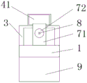
Fig. 1 is a schematic front view of a preferred embodiment of the present invention;
fig. 2 is a schematic side view of a preferred embodiment of the present invention;
fig. 3 is a schematic top view of a preferred embodiment of the present invention.
Description of reference numerals:
01. drawing the platform; 02. A steel wire drawing machine; 03. A gantry support;
04. a cleaning mechanism; 41. A warm water tank; 42. A spray head;
43. a warm water pipe; 5. A water storage tank; 6. A drain pipe;
7. a water removal mechanism; 71. A support plate; 72. Scraping a blade;
73. a baffle; 8. A steel wire; 9. A support frame;
Detailed Description
The technical solution of the present invention will be clearly and completely described with reference to the accompanying drawings. In the description of the present invention, it should be noted that the terms "center", "upper", "lower", "left", "right", "vertical", "horizontal", "inner", "outer", and the like indicate orientations or positional relationships based on the orientations or positional relationships shown in the drawings, and are only for convenience of description and simplification of description, but do not indicate or imply that the device or element referred to must have a specific orientation, be constructed and operated in a specific orientation, and thus, should not be construed as limiting the present invention. Furthermore, the terms "first," "second," and "third" are used for descriptive purposes only and are not to be construed as indicating or implying a relative importance.
In the description of the present invention, it is to be noted that, unless otherwise explicitly specified or limited, the terms "mounted," "connected," and "connected" are to be construed broadly, and may be, for example, fixedly connected, detachably connected, or integrally connected; can be mechanically or electrically connected; they may be connected directly or indirectly through intervening media, or they may be interconnected between two elements. The specific meaning of the above terms in the present invention can be understood in specific cases to those skilled in the art.
The present invention will be further explained with reference to the accompanying drawings.
Please combine and refer to fig. 1-3, the utility model relates to a dust cleaning device is drawn on steel wire surface, including drawing platform 1, drawing platform 1's last fixed surface is connected with steel wire drawbench 2, steel wire drawbench 2's output is extracted steel wire 8, drawing platform 1 is located upper fixed surface on steel wire drawbench 2 right side and is connected with gantry support 3, gantry support 3's upper surface is equipped with cleaning mechanism 4, drawing platform 1's upper surface has seted up aqua storage tank 5, the fixed intercommunication in bottom of aqua storage tank 5 has drain pipe 6, drawing platform 1 is located the upper fixed surface on gantry support 3 right side and is connected with dewatering mechanism 7, drawing platform 1's lower extreme fixedly connected with support frame 9.
Cleaning mechanism 4 includes warm water tank 41, and warm water tank 41 fixed connection is on the upper surface of gantry support 3, and lower surface center department fixedly connected with shower nozzle 42 of gantry support 3, through-hole and the inside intercommunication of warm water tank 41 that the central department of the end of intaking of shower nozzle 42 was seted up through gantry support 3, and the water spray end of shower nozzle 42 is just to steel wire 8, and fixed intercommunication has warm water pipe 43 on the lateral wall of warm water tank 41 top, washes out the drawing dust on steel wire 8 surface.
The dewatering mechanism 7 comprises a supporting plate 71, the supporting plate 71 is fixedly connected to the upper surface of the drawing platform 1, a scraping blade 72 is sleeved inside the supporting plate 71, the scraping blade 72 is in contact with the surface of the steel wire 8, and two guide plates 73 are respectively and fixedly connected to two sides of the side wall of the supporting plate 71 close to the cleaning mechanism 4, so as to scrape water and drawing dust on the surface of the steel wire 8.
The water storage tank 5 is positioned under the cleaning mechanism 4, the supporting plate 71 is positioned at the right opening of the water storage tank 5, so that warm water sprayed by the spray head 42 flows into the water storage tank 5, water scraped by the scraping blade 72 flows into the water storage tank 5, and cleaning is facilitated.
The scraping blade 72 is made of rubber, so that the steel wire 8 is prevented from being damaged, and the scraping blade 72 made of the rubber can scrape the surface of the steel wire 8 cleanly.
Specifically, when the device is used, the steel wire drawing machine 2 is started by inputting the steel wire 8 into the warm water tank 41 through the warm water pipe 43, the steel wire 8 is pulled out from the output end of the steel wire drawing machine 2, and the steel wire 8 moves to the position below the gantry support 3. Open shower nozzle 42, 8 blowout of steel wire are aimed at with the warm water to shower nozzle 42, wash steel wire 8, and then wash the drawing dust on steel wire 8 surface, advance the steel wire 8 who washes and remove right, scrape steel wire 8 surface through doctor-bar 72, and then strike off the drawing dust on steel wire 8 surface and that do not wash, pass through the leading-in aqua storage tank 5 inside of guide plate 73 with water and drawing dust, and then accomplish the clearance to the steel wire, prevent that 8 surface adhesion of steel wire has the drawing dust to cause the influence to follow-up technology, and then prevent to cause the influence to the product percent of pass of steel wire 8, through the waste water eduction gear of drain pipe 6 with 5 insides of aqua storage tank.
The foregoing is only a preferred embodiment of the present invention, and it should be noted that, for those skilled in the art, a plurality of improvements and decorations can be made without departing from the principle of the present invention, and these improvements and decorations should also be regarded as the protection scope of the present invention.
Other parts not described in detail in the present invention belong to the prior art, and are not described herein again.
Finally, it should be noted that: the above embodiments are only used to illustrate the technical solution of the present invention, and not to limit the same; although the present invention has been described in detail with reference to the foregoing embodiments, it should be understood by those skilled in the art that: the technical solutions described in the foregoing embodiments may still be modified, or some or all of the technical features may be equivalently replaced; such modifications and substitutions do not depart from the spirit and scope of the present invention.
Claims (6)
1. The utility model provides a dust cleaning device is drawn on steel wire surface, its characterized in that, including drawing platform (1), the last fixed surface of drawing platform (1) is connected with steel wire drawbench (2), steel wire (8) are extracted to the output of steel wire drawbench (2), drawing platform (1) is located upper fixed surface on steel wire drawbench (2) right side and is connected with longmen support (3), the upper surface of longmen support (3) is equipped with clearance mechanism (4), aqua storage tank (5) have been seted up to the upper surface of drawing platform (1), the fixed intercommunication in bottom of aqua storage tank (5) has drain pipe (6), the last fixed surface that drawing platform (1) is located longmen support (3) right side is connected with dewatering mechanism (7), the lower extreme fixedly connected with support frame (9) of drawing platform (1).
2. The steel wire surface drawing dust cleaning device according to claim 1, wherein the cleaning mechanism (4) comprises a warm water tank (41), the warm water tank (41) is fixedly connected to the upper surface of the gantry support (3), a nozzle (42) is fixedly connected to the center of the lower surface of the gantry support (3), the water inlet end of the nozzle (42) is communicated with the inside of the warm water tank (41) through a through hole formed in the center of the gantry support (3), the water spraying end of the nozzle (42) faces the steel wire (8), and a warm water pipe (43) is fixedly communicated with the side wall of the top end of the warm water tank (41).
3. The steel wire surface drawing dust cleaning device according to claim 1, wherein the water removing mechanism (7) comprises a support plate (71), the support plate (71) is fixedly connected to the upper surface of the drawing platform (1), a scraping blade (72) is sleeved inside the support plate (71), the scraping blade (72) is in surface contact with the steel wire (8), and two guide plates (73) are respectively and fixedly connected to two sides of the side wall of the support plate (71) close to the cleaning mechanism (4).
4. A steel wire surface drawing dust cleaning device according to claim 1, characterized in that the water storage tank (5) is located right below the cleaning mechanism (4).
5. A steel wire surface drawing dust cleaning device according to claim 3, characterized in that the support plate (71) is located at the right side opening of the water storage tank (5).
6. The steel wire surface drawing dust cleaning device according to claim 3, wherein the material of the scraping blade (72) is rubber.
Priority Applications (1)
| Application Number | Priority Date | Filing Date | Title |
|---|---|---|---|
| CN201921029269.7U CN210632677U (en) | 2019-07-04 | 2019-07-04 | Steel wire surface drawing dust cleaning device |
Applications Claiming Priority (1)
| Application Number | Priority Date | Filing Date | Title |
|---|---|---|---|
| CN201921029269.7U CN210632677U (en) | 2019-07-04 | 2019-07-04 | Steel wire surface drawing dust cleaning device |
Publications (1)
| Publication Number | Publication Date |
|---|---|
| CN210632677U true CN210632677U (en) | 2020-05-29 |
Family
ID=70796353
Family Applications (1)
| Application Number | Title | Priority Date | Filing Date |
|---|---|---|---|
| CN201921029269.7U Active CN210632677U (en) | 2019-07-04 | 2019-07-04 | Steel wire surface drawing dust cleaning device |
Country Status (1)
| Country | Link |
|---|---|
| CN (1) | CN210632677U (en) |
Cited By (2)
| Publication number | Priority date | Publication date | Assignee | Title |
|---|---|---|---|---|
| CN114311251A (en) * | 2020-10-10 | 2022-04-12 | 广东博智林机器人有限公司 | Steel wire cleaning mechanism and steel wire cutting plate blank device |
| CN116371959A (en) * | 2023-06-01 | 2023-07-04 | 江苏申源集团有限公司 | Stainless steel wire powdering device |
-
2019
- 2019-07-04 CN CN201921029269.7U patent/CN210632677U/en active Active
Cited By (3)
| Publication number | Priority date | Publication date | Assignee | Title |
|---|---|---|---|---|
| CN114311251A (en) * | 2020-10-10 | 2022-04-12 | 广东博智林机器人有限公司 | Steel wire cleaning mechanism and steel wire cutting plate blank device |
| CN116371959A (en) * | 2023-06-01 | 2023-07-04 | 江苏申源集团有限公司 | Stainless steel wire powdering device |
| CN116371959B (en) * | 2023-06-01 | 2023-08-01 | 江苏申源集团有限公司 | Stainless steel wire powdering device |
Similar Documents
| Publication | Publication Date | Title |
|---|---|---|
| CN210632677U (en) | Steel wire surface drawing dust cleaning device | |
| CN204018309U (en) | With the aloe washing machine of automatic pollutant removal | |
| CN108580371B (en) | Double-sided cleaning device for flat castings | |
| CN207836487U (en) | A kind of multi-functional broiler feeding cage | |
| CN212944326U (en) | Cleaning device for hydraulic cylinder assembly | |
| CN105214988A (en) | A kind of wax-pattern transport cleaning device | |
| CN210059171U (en) | Ultrasonic circulating cleaning spray head device | |
| CN209873117U (en) | Nickel-iron-chromium electrothermal alloy pickling treatment device | |
| CN211493364U (en) | Ink box cleaning device for color press | |
| CN203462139U (en) | Copper alloy wire washing device | |
| CN209428067U (en) | A kind of wet mud scraper plate lifting device | |
| CN208373725U (en) | A kind of dust-extraction unit of power equipment | |
| CN205907368U (en) | Electroplating workpiece device that degreases | |
| CN112916441A (en) | Residual anode cleaning device capable of being hung in electrolytic refining cell | |
| CN217511379U (en) | Electroplating solution filters cotton core cleaning machine | |
| CN214710238U (en) | Novel fruit cleaning machine | |
| CN202824001U (en) | Cleaning machine used for cleaning glass | |
| CN211660587U (en) | Conveniently-taken galvin arc quenching sheet electroplating cleaning device | |
| CN215967985U (en) | Flushing system of axle housing polishing equipment | |
| CN214078057U (en) | Cleaning device for alloy material | |
| CN205146762U (en) | Belt cleaning device is carried to wax matrix | |
| CN212349799U (en) | Barreled water outer barrel cleaning equipment | |
| CN208912756U (en) | A kind of scrap glass recovery and rinsing device | |
| CN217144926U (en) | 3D printer shell with clean effect | |
| CN109967423A (en) | A kind of machine components high-efficiency washing device |
Legal Events
| Date | Code | Title | Description |
|---|---|---|---|
| GR01 | Patent grant | ||
| GR01 | Patent grant |