CN210576293U - Single high-capacity battery - Google Patents
Single high-capacity battery Download PDFInfo
- Publication number
- CN210576293U CN210576293U CN201921423057.7U CN201921423057U CN210576293U CN 210576293 U CN210576293 U CN 210576293U CN 201921423057 U CN201921423057 U CN 201921423057U CN 210576293 U CN210576293 U CN 210576293U
- Authority
- CN
- China
- Prior art keywords
- plates
- positive
- line
- battery
- negative
- Prior art date
- Legal status (The legal status is an assumption and is not a legal conclusion. Google has not performed a legal analysis and makes no representation as to the accuracy of the status listed.)
- Active
Links
Images


Classifications
-
- Y—GENERAL TAGGING OF NEW TECHNOLOGICAL DEVELOPMENTS; GENERAL TAGGING OF CROSS-SECTIONAL TECHNOLOGIES SPANNING OVER SEVERAL SECTIONS OF THE IPC; TECHNICAL SUBJECTS COVERED BY FORMER USPC CROSS-REFERENCE ART COLLECTIONS [XRACs] AND DIGESTS
- Y02—TECHNOLOGIES OR APPLICATIONS FOR MITIGATION OR ADAPTATION AGAINST CLIMATE CHANGE
- Y02E—REDUCTION OF GREENHOUSE GAS [GHG] EMISSIONS, RELATED TO ENERGY GENERATION, TRANSMISSION OR DISTRIBUTION
- Y02E60/00—Enabling technologies; Technologies with a potential or indirect contribution to GHG emissions mitigation
- Y02E60/10—Energy storage using batteries
-
- Y—GENERAL TAGGING OF NEW TECHNOLOGICAL DEVELOPMENTS; GENERAL TAGGING OF CROSS-SECTIONAL TECHNOLOGIES SPANNING OVER SEVERAL SECTIONS OF THE IPC; TECHNICAL SUBJECTS COVERED BY FORMER USPC CROSS-REFERENCE ART COLLECTIONS [XRACs] AND DIGESTS
- Y02—TECHNOLOGIES OR APPLICATIONS FOR MITIGATION OR ADAPTATION AGAINST CLIMATE CHANGE
- Y02P—CLIMATE CHANGE MITIGATION TECHNOLOGIES IN THE PRODUCTION OR PROCESSING OF GOODS
- Y02P70/00—Climate change mitigation technologies in the production process for final industrial or consumer products
- Y02P70/50—Manufacturing or production processes characterised by the final manufactured product
Abstract
The utility model discloses a monomer large capacity battery, include: a battery jar, a battery cover and a plurality of clapboards; the battery cover is detachably mounted to the notch of the battery jar; the plurality of partition plates are arranged in the battery jar and partition the battery jar to form a plurality of unit spaces; a plurality of positive plates, a plurality of negative plates and a plurality of separators are arranged in the unit space; the plurality of positive plates, the plurality of negative plates and the plurality of separators are sequentially arranged in the unit space according to the sequence of the positive plates, the separators and the negative plates; a first bus bar and a second bus bar are fixed above the positive plates and the negative plates; the positive plates are electrically connected to the first bus bar; the plurality of negative plates are electrically connected to the second bus plate; the first bus bar is provided with a positive terminal; the second bus bar is provided with a negative terminal; the partition plate is formed with a plurality of liquid passing holes. The single large-capacity battery has the advantages of light weight, large specific energy and easy maintenance.
Description
Technical Field
The utility model relates to a lead acid battery field, concretely relates to monomer large capacity battery.
Background
The traditional high-capacity battery is formed by connecting two single batteries into a shell in parallel through two positive poles and two negative poles with the outside, and has heavier weight, low specific energy and higher cost. And the connection between two single batteries and the installation and maintenance operation of the conventional large-capacity battery are very inconvenient.
SUMMERY OF THE UTILITY MODEL
The utility model provides a monomer large capacity battery adopts following technical scheme:
a single large capacity battery comprising: a battery container, a battery cover for covering a notch of the battery container to seal the battery container, and a plurality of separators; the battery cover is detachably mounted to the notch of the battery jar; a plurality of separators installed in the battery case and partitioning the battery case to form a plurality of unit spaces for accommodating an electrolyte; a plurality of positive plates, a plurality of negative plates and a plurality of partition plates for isolating the positive plates from the negative plates are arranged in the unit space; the plurality of positive plates, the plurality of negative plates and the plurality of separators are sequentially arranged in the unit space according to the sequence of the positive plates, the separators and the negative plates; a first bus bar and a second bus bar are fixed above the positive plates and the negative plates; the positive plates are electrically connected to the first bus bar; the plurality of negative plates are electrically connected to the second bus plate; the first bus bar is provided with a positive terminal for connecting external electric equipment to provide power; the second bus plate is provided with a negative terminal for connecting external electric equipment to provide power; the battery cover is formed with a through hole for the positive and negative terminals to pass through to extend to the outside of the battery cover; the separator is provided with a plurality of liquid through holes for electrolyte to pass through; the liquid passing holes are communicated with two adjacent unit spaces.
Further, the partitions are disposed at intervals along the first straight line and the volumes of the plurality of unit spaces into which the battery case is divided are equal.
Further, the positive electrode plate, the separator, the negative electrode plate and the separator are parallel to each other and the first line is perpendicular to the plane of the separator.
Further, the number of the separators is 3; the number of positive and negative terminals was 4.
Further, 4 positive terminals are arranged along a second line; 4 negative terminals are arranged along a third line; the second line and the third line are parallel to the first line.
Further, the battery cover is provided with a plurality of safety valves for respectively connecting the plurality of cell spaces to adjust the air pressure in the cell spaces; a plurality of safety valves are arranged along a fourth straight line; the fourth line is parallel to the first line.
Further, the safety valve is located between the positive terminal and the negative terminal and has a distance to the positive terminal equal to a distance to the negative terminal.
Further, the plurality of first bus plates are arranged along a fifth line; the plurality of second bus plates are arranged along a sixth line; the fifth line, the sixth line and the first line are parallel to each other.
The utility model discloses an useful part lies in the monomer large capacity battery that provides and separates into a plurality of unit spaces with the battery jar through a plurality of baffles, has a plurality of battery cells in other words, has effectively improved specific energy when reducing self weight to the cost is lower. Meanwhile, the partition plate is provided with a plurality of liquid penetrating holes, so that electrolytes in the plurality of unit spaces can mutually circulate, and the balance of the storage capacity of the electrolytes in the plurality of unit spaces is ensured. The internal structure and the mounting structure of the single high-capacity battery are simple, and later maintenance is facilitated.
Drawings
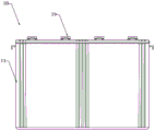
Fig. 1 is a front view of a single large capacity battery of the present invention;
fig. 2 is a plan view of a single large capacity battery in fig. 1;
fig. 3 is a left side view of the unit large capacity battery of fig. 1;
fig. 4 is a schematic diagram of the single large capacity battery in fig. 2 with a battery cover removed;
fig. 5 is a schematic view of a battery can and a separator of the unit large capacity battery of fig. 4;
fig. 6 is a sectional view of the unit large capacity battery in fig. 4.
The battery pack includes a single large-capacity battery 10, a battery can 11, a battery cover 12, a through hole 121, a separator 13, a liquid passing hole 131, a cell space 14, a first bus bar 15, a positive electrode terminal 16, a second bus bar 17, a negative electrode terminal 18, a safety valve 19, a first straight line 20, a positive electrode plate 21, a negative electrode plate 22, and a separator 23.
Detailed Description
The present invention will be described in detail with reference to the accompanying drawings and specific embodiments.
As shown in fig. 1 to 6, a single large capacity battery 10 includes: a battery can 11, a battery cover 12, and a plurality of separators 13. The battery cover 12 is used to cover the notch of the battery can 11 to seal the battery can 11. The battery cover 12 is detachably mounted to the notch of the battery container 11 to facilitate the maintenance of the unit large-capacity battery 10 by opening the battery cover 12. A plurality of partitions 13 are installed in the battery case 11 and partition the battery case 11 to form a plurality of unit spaces 14. The plurality of unit spaces 14 serve to accommodate an electrolyte, thereby achieving a function of one battery container 11 having a plurality of unit batteries, and further improving specific energy of the unit large-capacity battery 10. Meanwhile, the single large-capacity battery 10 having one battery well 11 has a small weight and a low cost.
Further, a plurality of positive electrode plates 21, a plurality of negative electrode plates 22, and a plurality of separators 23 are provided in the cell space 14. The separator 23 is used to separate the positive electrode plate 21 from the negative electrode plate 22, so as to ensure that the positive electrode plate 21 and the negative electrode plate 22 do not interfere with each other. Specifically, the plurality of positive electrode plates 21, the plurality of negative electrode plates 22, and the plurality of separators 23 are arranged in the order of the positive electrode plates 21, the separators 23, and the negative electrode plates 22 in the unit space 14, that is, the separators 23 are installed between the positive electrode plates 21 and the negative electrode plates 22.
Meanwhile, the first bus bar 15 and the second bus bar 17 are fixed above the plurality of positive electrode plates 21 and the plurality of negative electrode plates 22. The plurality of positive plates 21 are electrically connected to the first bus bar 15. The plurality of negative electrode plates 22 are electrically connected to the second bus plate 17. The arrangement is such that the current of the positive electrode plate 21 can be transmitted to the external electric device through the first bus bar 15, and the current of the negative electrode plate 22 can be transmitted to the external electric device through the second bus bar 17.
More specifically, the first bus bar 15 is provided with a positive terminal 16. The positive terminal 16 is used for connecting an external electric device to supply power by an output current. The second bus plate 17 is provided with a negative terminal 18. The negative terminal 18 is used to connect an external power consumer to supply power by outputting current. The battery cover 12 is formed with a through hole 121. The through hole 121 is used for the positive terminal 16 and the negative terminal 18 to pass through to extend to the outside of the battery cover 12 for electrically connecting to an external electric device.
Further, the partition 13 is formed with a plurality of liquid passing holes 131. The liquid passing holes 131 are for passing the electrolyte in the plurality of unit spaces 14. Specifically, the liquid passing hole 131 communicates the adjacent two unit spaces 14.
Specifically, the separator 13 is formed with a plurality of liquid passing holes 131 so that the electrolytes in the plurality of cell spaces 14 can flow through each other, thereby ensuring the balance of the amount of electricity stored in the electrolytes in the plurality of cell spaces 14. The internal structure and the mounting structure of the single large-capacity battery 10 are simple, and the later maintenance is facilitated.
As a specific embodiment, the partitions 13 are spaced along the first line 20. Meanwhile, the partition plate 13 divides the battery case 11 into a plurality of unit spaces 14 having equal volumes. This arrangement can further ensure the balance of the electric quantity in the plurality of unit spaces 14.
As a specific embodiment, the positive electrode plate 21, the separator 23, the negative electrode plate 22, and the separator 13 are parallel to each other and the first straight line 20 is perpendicular to the plane of the separator 13. This arrangement can ensure the stability of the mounting structure.
As a specific embodiment, the number of the partition plates 13 is 3. The battery case 11 is partitioned into 4 unit spaces 14 by 3 partitions 13. The four unit spaces 14 have 4 positive terminals 16 and 4 negative terminals 18.
Alternatively, the number of baffles may be adjusted to the actual production requirements. Meanwhile, the number of the positive terminals and the number of the negative terminals are correspondingly adjusted.
Specifically, 4 positive terminals 16 are arranged along the second line. The 4 negative terminals 18 are arranged along a third line. The second and third lines are parallel to the first line 20.
As a specific embodiment, the battery cover 12 is provided with a plurality of safety valves 19. The safety valves 19 are respectively used to connect the cell spaces 14 to adjust the air pressure in the cell spaces 14, thereby ensuring the safety of the single large-capacity battery 10. A plurality of safety valves 19 are arranged along a fourth line. The fourth line is parallel to the first line 20.
As a specific embodiment, the safety valve 19 is located between the positive terminal 16 and the negative terminal 18 and has the same distance to the positive terminal 16 and the negative terminal 18.
As a specific embodiment, the plurality of first bus plates 15 are arranged along a fifth straight line. The plurality of second bus plates 17 are arranged along a sixth line. The fifth line, the sixth line and the first line 20 are parallel to each other.
Further, guide rails 16 are formed on both sides of the overlapping support rods 15 of the two adjacent placement frames 12.
The foregoing illustrates and describes the principles, general features, and advantages of the present invention. It should be understood by those skilled in the art that the above embodiments do not limit the present invention in any way, and all technical solutions obtained by adopting equivalent replacement or equivalent transformation fall within the protection scope of the present invention.
Claims (8)
1. A single large capacity battery, comprising: a battery container, a battery cover for covering a notch of the battery container to seal the battery container, and a plurality of separators; the battery cover is detachably mounted to the notch of the battery jar; a plurality of separators installed in the battery case and partitioning the battery case to form a plurality of unit spaces for accommodating an electrolyte; a plurality of positive plates, a plurality of negative plates and a plurality of separators for separating the positive plates from the negative plates are arranged in the unit space; a plurality of the positive electrode plates, a plurality of the negative electrode plates, and a plurality of the separators are arranged in the unit space in this order; a first bus bar and a second bus bar are fixed above the positive plates and the negative plates; the positive plates are electrically connected to the first bus bar; the negative plates are electrically connected to the second bus plate; the first bus bar is provided with a positive terminal for connecting external electric equipment to provide power; the second bus plate is provided with a negative terminal for connecting external electric equipment to provide power; the battery cover is formed with a through hole for the positive and negative terminals to pass through to extend to the outside of the battery cover; the separator is provided with a plurality of liquid through holes for electrolyte to pass through; the liquid passing holes are communicated with two adjacent unit spaces.
2. The single large capacity battery according to claim 1,
the partitions are spaced along a first straight line and have equal volumes of the plurality of unit spaces into which the battery case is divided.
3. The single large capacity battery according to claim 2,
the positive plate, the separator, the negative plate and the separator are parallel to each other, and the first straight line is perpendicular to the plane of the separator.
4. The single large capacity battery according to claim 3,
the number of the partition boards is 3; the number of the positive electrode terminals and the negative electrode terminals is 4.
5. The single large capacity battery according to claim 4,
4 positive terminals are arranged along a second straight line; 4 of the negative terminals are arranged along a third line; the second line and the third line are parallel to the first line.
6. The single large capacity battery according to claim 2,
the battery cover is provided with a plurality of safety valves respectively used for connecting the plurality of unit spaces to adjust the air pressure in the unit spaces; a plurality of said safety valves are arranged along a fourth line; the fourth line is parallel to the first line.
7. The single large capacity battery according to claim 6,
the safety valve is located between the positive terminal and the negative terminal and has a distance to the positive terminal equal to a distance to the negative terminal.
8. The single large capacity battery according to claim 2,
the plurality of first bus plates are arranged along a fifth straight line; the plurality of second bus plates are arranged along a sixth line; the fifth line, the sixth line and the first line are parallel to each other.
Priority Applications (1)
| Application Number | Priority Date | Filing Date | Title |
|---|---|---|---|
| CN201921423057.7U CN210576293U (en) | 2019-08-29 | 2019-08-29 | Single high-capacity battery |
Applications Claiming Priority (1)
| Application Number | Priority Date | Filing Date | Title |
|---|---|---|---|
| CN201921423057.7U CN210576293U (en) | 2019-08-29 | 2019-08-29 | Single high-capacity battery |
Publications (1)
| Publication Number | Publication Date |
|---|---|
| CN210576293U true CN210576293U (en) | 2020-05-19 |
Family
ID=70660759
Family Applications (1)
| Application Number | Title | Priority Date | Filing Date |
|---|---|---|---|
| CN201921423057.7U Active CN210576293U (en) | 2019-08-29 | 2019-08-29 | Single high-capacity battery |
Country Status (1)
| Country | Link |
|---|---|
| CN (1) | CN210576293U (en) |
Cited By (1)
| Publication number | Priority date | Publication date | Assignee | Title |
|---|---|---|---|---|
| CN110444820A (en) * | 2019-08-29 | 2019-11-12 | 卧龙电气驱动集团股份有限公司 | Monomer high capacity cell |
-
2019
- 2019-08-29 CN CN201921423057.7U patent/CN210576293U/en active Active
Cited By (1)
| Publication number | Priority date | Publication date | Assignee | Title |
|---|---|---|---|---|
| CN110444820A (en) * | 2019-08-29 | 2019-11-12 | 卧龙电气驱动集团股份有限公司 | Monomer high capacity cell |
Similar Documents
| Publication | Publication Date | Title |
|---|---|---|
| KR101252950B1 (en) | Battery module providing improved fixing structure for end plate | |
| US20210143516A1 (en) | Lead-acid battery and battery pack | |
| US9077020B2 (en) | Battery module | |
| US20150079427A1 (en) | Case system, battery and battery rack with improved stacking | |
| CN202523780U (en) | Lithium battery module | |
| CN216872133U (en) | Battery and consumer | |
| CN216872137U (en) | Battery and electric equipment | |
| CN111769245A (en) | Battery with battery cells connected in series-parallel and battery module | |
| CN210576293U (en) | Single high-capacity battery | |
| CN209804827U (en) | Lead-acid storage battery capable of avoiding acid stratification | |
| CN102403479A (en) | Connection method for square battery pack internal electrical cores and square battery pack thereof | |
| CN216872190U (en) | Battery and consumer | |
| CN115843398B (en) | Battery, electric device, method and equipment for preparing battery | |
| CN213692277U (en) | Lead-acid storage battery | |
| CN201927679U (en) | Linear storage battery for electric vehicle | |
| CN116325326A (en) | Battery, electric device, method and equipment for preparing battery | |
| CN203589168U (en) | Jointed storage battery | |
| CN210063377U (en) | Hybrid power device of hydrogen fuel cell and lithium battery | |
| CN112259916A (en) | Lead-acid storage battery and manufacturing method thereof | |
| CN116349062A (en) | Battery box, battery, electric equipment, and method and equipment for preparing battery | |
| CN202153548U (en) | Square storage battery pack | |
| CN202153547U (en) | Square battery pack | |
| CN218351595U (en) | Power battery | |
| CN210296484U (en) | Energy storage battery pack | |
| CN218274931U (en) | Battery energy storage system architecture |
Legal Events
| Date | Code | Title | Description |
|---|---|---|---|
| GR01 | Patent grant | ||
| GR01 | Patent grant |