CN210569639U - Quick drying draining rack - Google Patents
Quick drying draining rack Download PDFInfo
- Publication number
- CN210569639U CN210569639U CN201921426577.3U CN201921426577U CN210569639U CN 210569639 U CN210569639 U CN 210569639U CN 201921426577 U CN201921426577 U CN 201921426577U CN 210569639 U CN210569639 U CN 210569639U
- Authority
- CN
- China
- Prior art keywords
- water
- air
- supporting
- air outlet
- supporting frame
- Prior art date
- Legal status (The legal status is an assumption and is not a legal conclusion. Google has not performed a legal analysis and makes no representation as to the accuracy of the status listed.)
- Active
Links
Images
Landscapes
- Drying Of Solid Materials (AREA)
Abstract
The utility model discloses a quick drying draining rack, which comprises a supporting frame, wherein an air heater is arranged at the bottom of the supporting frame, a plurality of supporting plates inclined to one side are longitudinally arranged on the supporting frame above the air heater at intervals, an air outlet of the air heater is hermetically communicated with an air supply main pipe, a plurality of air supply branch pipes communicated with the air supply main pipe are arranged below each supporting plate at intervals, a plurality of air outlet pipes which vertically and upwards pass through the supporting plates are arranged on the air supply branch pipes at intervals along the length direction, and air outlet holes are uniformly distributed on the pipe wall of the air outlet pipe above the supporting plates; a water receiving groove is arranged on the lower inclined edge close to the supporting plate, the water receiving groove is inclined towards one end, and the lower inclined end of the water receiving groove is communicated with a water storage box arranged at the bottom of the supporting frame through a water conveying pipeline. The utility model has the advantages of simple structure and simple operation; the waterlogging caused by excessive rainfall efficiency of container after improving by a wide margin and washing satisfies the laboratory and uses, reduces the input cost of laboratory container, avoids the container inner wall to expose for a long time, reduces the container and receives the pollution risk.
Description
Technical Field
The utility model belongs to the technical field of the cleaning equipment technique and specifically relates to a quick drying draining rack after container washs.
Background
Containers (such as beakers, rubber barrels, stainless steel barrels, conical flasks and the like) are frequently used in production, experiments and life. The method has the advantages that after the existing container is cleaned, a large number of water drops adhere to the surface of the inner wall, the container can be reused after the water drops of the container are drained, the water drops on the inner wall of the existing container are naturally dried, the efficiency of the method is very low, particularly, in the using process of a laboratory, the containers with a large number of reserves are needed to meet frequent and large number of experimental operations, and the investment is increased to a certain extent; in addition, the container is completely dried for a long time by adopting a natural drying method, and is exposed for a long time, so that the risk of pollution during the drying control of the container is easily increased.
Disclosure of Invention
The utility model aims to provide a simple structure, the quick drying draining rack easy and simple to handle.
In order to achieve the above purpose, the utility model can adopt the following technical proposal:
the utility model discloses a quick drying draining rack, including braced frame, braced frame's bottom is provided with the air heater, longitudinally interval range has a plurality of to the layer board of a side slope on the braced frame of air heater top, and sealed intercommunication has the person in charge of supplying gas on the air outlet of air heater, and equal interval range has a plurality of branch pipes of supplying gas that are linked together with the person in charge of supplying gas below each the layer board, the branch pipe of supplying gas is last to be provided with a plurality of air-out pipes that pass the layer board perpendicularly upwards along length direction interval, is located the layer board top the air-out pipe wall on the equipartition have the exhaust vent; and a water receiving groove is arranged on the lower inclined edge close to the supporting plate, inclines towards one end, and is communicated with a water storage box arranged at the bottom of the supporting frame through a water conveying pipeline at the lower inclined end.
The water storage box is an upper opening box body movably arranged on one side of the air heater, and the water outlet end of the water conveying pipeline extends into the water storage box; and a water baffle is arranged on the upper surface close to the air heater, and the water baffle inclines downwards from one side to extend to the upper part of the opening of the water storage box.
The supporting frame is a stainless steel frame body, and the supporting plate is a transparent toughened glass plate.
And universal mute wheels with brake devices are arranged at four corners of the bottom of the supporting frame.
The utility model has the advantages of simple structure and simple operation. The cleaned container is reversely buckled on the air outlet pipe penetrating through the supporting plate, then the hot air blower is started, hot air blown out by the hot air blower sequentially passes through the air supply main pipe and the air supply branch pipe and is finally blown out from air outlet holes on the air outlet pipe, and hot air is uniformly blown to the inner wall of the container clamped on the air outlet pipe, so that the aim of quickly draining water drops on the surface of the inner wall of the container is fulfilled, the draining efficiency of the cleaned container is greatly improved, the laboratory use with large usage is met, the investment cost of the container in a laboratory is reduced, meanwhile, the inner wall of the container is prevented from being exposed outside for a long time, and the pollution risk of the container is reduced; in addition, the supporting plate inclined to one side is matched with the water receiving tank and the water conveying pipeline, water drops blown out by hot air can be collected into the water storage box, resources are saved, and the experimental environment is prevented from being splashed.
Drawings
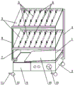
Fig. 1 is a schematic structural diagram of the present invention.
Detailed Description
As shown in fig. 1, the quick drying draining rack of the utility model comprises a support frame 1, which is made of stainless steel and can effectively prevent water; the bottom of the supporting frame 1 is provided with the air heater 2, two groups of supporting plates 3 inclined towards one side are longitudinally arranged on the supporting frame 1 above the air heater 2 at intervals, the number of the supporting plates 3 can be increased according to needs, and the height of the supporting frame 1 is increased; in addition, the supporting plates 3 can be transparent toughened glass plates, and the two groups of supporting plates 3 are inclined towards the same side.
The air outlet of the air heater 2 is hermetically communicated with an air supply main pipe 4, a plurality of air supply branch pipes 5 communicated with the air supply main pipe 4 are arranged below each supporting plate 3 at intervals, a plurality of air outlet pipes 6 vertically and upwards penetrating through the supporting plates 3 are arranged on the air supply branch pipes 5 at intervals along the length direction, and the number of the air supply branch pipes 5 and the number of the air outlet pipes 6 are determined according to the specific size of the supporting plate 3 and the volume of a container to be dried; the pipe wall of the air outlet pipe 6 above the supporting plate 3 is evenly provided with air outlet holes, so that hot air blown by the air heater 2 can be more evenly blown to the inner wall of the container reversely buckled on the air outlet pipe 6.
A water receiving tank 7 is arranged close to the inclined lower edge of the supporting plate 3, the water receiving tank 7 is inclined towards one end, the inclined lower end of the water receiving tank is communicated with a water storage box 9 arranged at the bottom of the supporting frame 1 through a water conveying pipeline 8, of course, the water receiving tank 7 can also be only inclined downwards from the bottom wall to the end of the water conveying pipeline 8, and the water falling into the water receiving tank 7 can be ensured to flow into the water conveying pipeline 8 quickly; the water storage box 9 is an upper opening box body movably arranged on one side of the air heater 2, so that water stored in the toppling water storage box 9 can be conveniently taken down, and the water outlet end of the water conveying pipeline 8 can extend into the water storage box 9; in order to prevent water from dropping onto the air heater 2 during the process of draining the container, a water baffle 10 is arranged on the upper surface close to the air heater 2, and the water baffle 10 inclines downwards from one side to extend to the upper part of the opening of the water storage box 9.
In addition, in order to move the device conveniently, universal mute wheels 12 with brake devices 11 can be arranged at the four corners of the bottom of the supporting frame 1.
When the device is used, the cleaned container is only required to be reversely buckled on the air outlet pipe 6 penetrating out of the supporting plate 3, then the air heater 2 is started, the air adjusting knob 13 of the air heater 2 is adjusted according to needs, hot air sequentially passes through the air supply main pipe 4 and the air supply branch pipe 5, and finally is blown out from the air outlet holes on the air outlet pipe 6 uniformly to blow hot air on the inner wall of the container clamped on the air outlet pipe 6, so that the aim of quickly draining water drops on the surface of the inner wall of the container is achieved, and the draining efficiency of the cleaned container is greatly improved; and the water drops blown down onto the supporting plate 3 by the hot air can slide towards the inclined lower edge and fall into the water receiving tank 7 to flow to the water storage box 9 through the water conveying pipeline 8, and when the water collected in the water storage box 9 reaches a certain amount, the water storage box 9 can be taken down to pour the water.
Claims (4)
1. The utility model provides a quick drying draining rack, includes braced frame (1), its characterized in that: the air heater is characterized in that an air heater (2) is arranged at the bottom of the supporting frame (1), a plurality of supporting plates (3) inclined to one side are longitudinally arranged on the supporting frame (1) above the air heater (2) at intervals, an air outlet of the air heater (2) is hermetically communicated with an air supply main pipe (4), a plurality of air supply branch pipes (5) communicated with the air supply main pipe (4) are arranged below each supporting plate (3) at intervals, a plurality of air outlet pipes (6) vertically and upwardly penetrating through the supporting plates (3) are arranged on the air supply branch pipes (5) at intervals along the length direction, and air outlet holes are uniformly distributed on the pipe walls of the air outlet pipes (6) above the supporting plates (3); a water receiving groove (7) is arranged on the lower inclined edge close to the supporting plate (3), the water receiving groove (7) is inclined towards one end, and the inclined lower end of the water receiving groove is communicated with a water storage box (9) arranged at the bottom of the supporting frame (1) through a water conveying pipeline (8).
2. The quick drying draining rack according to claim 1, wherein: the water storage box (9) is an upper opening box body movably arranged on one side of the air heater (2), and the water outlet end of the water conveying pipeline (8) extends into the water storage box (9); a water baffle (10) is arranged on the upper surface close to the air heater (2), and the water baffle (10) inclines downwards from one side to extend to the upper part of the opening of the water storage box (9).
3. The quick drying draining rack according to claim 1, wherein: the supporting frame (1) is a stainless steel frame body, and the supporting plate (3) is a transparent toughened glass plate.
4. The quick drying draining rack according to claim 1, wherein: universal silent wheels (12) with brake devices (11) are arranged at the four corners of the bottom of the supporting frame (1).
Priority Applications (1)
| Application Number | Priority Date | Filing Date | Title |
|---|---|---|---|
| CN201921426577.3U CN210569639U (en) | 2019-08-30 | 2019-08-30 | Quick drying draining rack |
Applications Claiming Priority (1)
| Application Number | Priority Date | Filing Date | Title |
|---|---|---|---|
| CN201921426577.3U CN210569639U (en) | 2019-08-30 | 2019-08-30 | Quick drying draining rack |
Publications (1)
| Publication Number | Publication Date |
|---|---|
| CN210569639U true CN210569639U (en) | 2020-05-19 |
Family
ID=70661038
Family Applications (1)
| Application Number | Title | Priority Date | Filing Date |
|---|---|---|---|
| CN201921426577.3U Active CN210569639U (en) | 2019-08-30 | 2019-08-30 | Quick drying draining rack |
Country Status (1)
| Country | Link |
|---|---|
| CN (1) | CN210569639U (en) |
-
2019
- 2019-08-30 CN CN201921426577.3U patent/CN210569639U/en active Active
Similar Documents
| Publication | Publication Date | Title |
|---|---|---|
| CN207430028U (en) | A kind of environmental type reviver desulfurization and dedusting exhaust gas cleaner | |
| CN210569639U (en) | Quick drying draining rack | |
| CN209140070U (en) | A kind of environment-friendly type laser removes plating appts | |
| CN217830092U (en) | Reaction vessel supporter | |
| CN201203341Y (en) | Condensate water-proof structure of damp-discharging system in drying room | |
| CN210595717U (en) | Container formula sewage treatment device | |
| CN210253325U (en) | Liquid bubble cleaning device for carrier tank of grinding head of semiconductor equipment | |
| CN211486977U (en) | Water bath dust removal device | |
| CN206447594U (en) | A kind of efficient ammonia nitrogen stripping tower | |
| CN204502735U (en) | A kind of high-efficiency spray tower | |
| CN203694883U (en) | Recycling system for absorption liquid | |
| CN208771185U (en) | A kind of environment-friendly type soda acid exhaust gas washing tower with multiple purifying function | |
| CN203525486U (en) | Wet type dust collector | |
| CN206006538U (en) | Container cabinet | |
| CN208275833U (en) | A kind of chemical experimental instrument cleaning plant | |
| CN211636006U (en) | Purification equipment for treating waste gas by biological method | |
| CN206924578U (en) | A kind of high efficiency wet scrubber | |
| CN207769563U (en) | A kind of plate film assembly | |
| CN204170589U (en) | A kind of tranquility environmental protection tourie for chemical industry equipment | |
| CN204260966U (en) | Nursing tray bogey | |
| CN211098295U (en) | Sulfur recovery tail gas treatment device | |
| CN110772905A (en) | Environment-friendly treatment cleaning device | |
| CN210700208U (en) | Fixing device is deposited to laboratory's instrument | |
| CN214516366U (en) | Workpiece surface cleaning and treating device | |
| CN105582763A (en) | Energy-saving device for non-asbestos silicate board production equipment |
Legal Events
| Date | Code | Title | Description |
|---|---|---|---|
| GR01 | Patent grant | ||
| GR01 | Patent grant |