CN210543707U - Reverse suction device of fiber rotary disc filter - Google Patents
Reverse suction device of fiber rotary disc filter Download PDFInfo
- Publication number
- CN210543707U CN210543707U CN201920722892.4U CN201920722892U CN210543707U CN 210543707 U CN210543707 U CN 210543707U CN 201920722892 U CN201920722892 U CN 201920722892U CN 210543707 U CN210543707 U CN 210543707U
- Authority
- CN
- China
- Prior art keywords
- support frame
- fixedly connected
- sewage
- suction device
- filtering ponds
- Prior art date
- Legal status (The legal status is an assumption and is not a legal conclusion. Google has not performed a legal analysis and makes no representation as to the accuracy of the status listed.)
- Active
Links
- 239000000835 fiber Substances 0.000 title claims abstract description 44
- 238000004140 cleaning Methods 0.000 claims abstract description 51
- 239000010865 sewage Substances 0.000 claims abstract description 48
- 238000005202 decontamination Methods 0.000 claims abstract description 9
- 230000003588 decontaminative effect Effects 0.000 claims abstract description 9
- 238000001914 filtration Methods 0.000 claims description 26
- 239000004744 fabric Substances 0.000 claims description 17
- 241000252254 Catostomidae Species 0.000 claims description 3
- 238000005096 rolling process Methods 0.000 claims 2
- 238000000034 method Methods 0.000 abstract description 9
- 235000009161 Espostoa lanata Nutrition 0.000 abstract description 2
- 240000001624 Espostoa lanata Species 0.000 abstract description 2
- XLYOFNOQVPJJNP-UHFFFAOYSA-N water Substances O XLYOFNOQVPJJNP-UHFFFAOYSA-N 0.000 description 15
- 239000012535 impurity Substances 0.000 description 9
- 230000000694 effects Effects 0.000 description 4
- 238000011001 backwashing Methods 0.000 description 3
- 239000007788 liquid Substances 0.000 description 2
- 230000004048 modification Effects 0.000 description 2
- 238000012986 modification Methods 0.000 description 2
- 239000002351 wastewater Substances 0.000 description 2
- 230000009286 beneficial effect Effects 0.000 description 1
- 239000000470 constituent Substances 0.000 description 1
- 238000010586 diagram Methods 0.000 description 1
- 230000003311 flocculating effect Effects 0.000 description 1
- 239000000463 material Substances 0.000 description 1
- 239000012528 membrane Substances 0.000 description 1
- 238000005192 partition Methods 0.000 description 1
- 239000002689 soil Substances 0.000 description 1
- 230000000087 stabilizing effect Effects 0.000 description 1
- 230000003068 static effect Effects 0.000 description 1
- 238000005406 washing Methods 0.000 description 1
Images

Landscapes
- Filtration Of Liquid (AREA)
Abstract
The utility model belongs to the technical field of sewage treatment equipment, in particular to a fiber rotary disc filter reverse suction device, which comprises a filter tank, wherein a stable support frame is lapped at the top of the filter tank, the lower surface of the stable support frame is fixedly connected with a sliding connection frame, the inside of the sliding connection frame is movably connected with a cleaning clamp support frame, one side inside the sliding connection frame is fixedly connected with a hydraulic telescopic rod, the output end of the hydraulic telescopic rod is fixedly connected with the back surface of the cleaning clamp support frame, the utility model is provided with a reverse suction sucking disc capable of moving up and down, when oil stain on the surface of the reverse suction disc needs to be cleaned, the reverse suction sucking disc is moved up to a crack between decontamination rollers, the outer surface of the decontamination rollers is sleeved with a cleaning cotton ball, and the surface of the reverse suction sucking disc can be cleaned by rotating the sucking disc cleaning clamp, and the operation process is simple and convenient, and the working efficiency of workers is greatly improved.
Description
Technical Field
The utility model belongs to the technical field of sewage treatment device, concretely relates to anti-suction device of fibre carousel filter.
Background
The fiber rotary disc filter is one of the most efficient filters at present, has good treatment effect, good effluent quality and stable operation, and is characterized in that raw water enters a filter tank from a water inlet pipeline and then enters a fiber rotary disc fixed around a central pipe, filter cloth is arranged on two sides of the fiber rotary disc of the cleaning clamp support frame, and the raw water flows out from a water outlet of the central pipe after being filtered by the filter cloth. The filter disc cleaning clamp support frame is characterized in that impurities trapped on filter cloth are continuously increased along with the continuous filter of the cleaning clamp support frame, clear water flowing out of a central tube is gradually reduced, the water level in the filter chamber is continuously increased, the central tube starts to rotate when the liquid level in the filter chamber reaches a set value, a backwashing device is started, a reverse suction sucker sucks away impurities on the fiber rotary disc cleaning clamp support frame, the impurities enter a drain pipe to be discharged, the water level in the filter chamber continuously drops along with the continuous washing, when the set liquid level value reaches the cleaning clamp support frame, the backwashing device automatically stops, the central tube also stops rotating, and the system enters a static filter process again. The prior art has the following problems:
1. the backwashing effect of the filter tank is possibly poor, because the suspended matters of the secondary treatment water are more, a layer of filter membrane is easily formed on the surface of the filter cloth, and the flocculating constituent is attached to the surface of the material and is not easy to fall off;
2. after the reverse suction sucker sucks the oil stains on the surface of the filter cloth into the sewage pipe, part of the oil stains are remained on the surface of the sucker and are difficult to clean.
SUMMERY OF THE UTILITY MODEL
To solve the problems set forth in the background art described above. The utility model provides a reverse suction device of fiber rotary disc filter has that the filter effect is good and be convenient for carry out the characteristics of clearing up the greasy dirt on the surface to reverse suction sucking disc.
In order to achieve the above object, the utility model provides a following technical scheme: a reverse suction device of a fiber rotary disc filter comprises a filter tank, wherein a stable support frame is lapped at the top of the filter tank, a sliding connection frame is fixedly connected to the lower surface of the stable support frame, a cleaning clip support frame is movably connected inside the sliding connection frame, a hydraulic telescopic rod is fixedly connected to one side inside the sliding connection frame, the output end of the hydraulic telescopic rod is fixedly connected to the back surface of the cleaning clip support frame, a motor is fixedly connected to one side of the cleaning clip support frame, the output end of the motor extends into the cleaning clip support frame and is fixedly connected with a cleaning clip rotating disc, a sucker cleaning clip is movably connected inside the cleaning clip support frame, a cleaning clip connecting shaft is fixedly connected to one side of a cleaning clip rotating disc, the other end of the cleaning clip connecting shaft is fixedly connected with a sucker cleaning clip, and a roller support frame is fixedly connected inside the sucker cleaning clip, and a decontamination roller is arranged in the roller support frame.
In order to make can clear up the greasy dirt on the filter cloth surface, as the utility model relates to a fibre carousel filter anti-suction device is preferred, the both sides at fibre carousel top all are provided with anti-suction sucking disc, anti-suction sucking disc's top fixedly connected with blowdown branch pipe.
In order to make the greasy dirt discharge in can following the filter tank, conduct the utility model relates to a reverse suction device of fibre carousel filter is preferred, the blowdown branch pipe run through the inside of blowdown support frame and with blowdown hose fixed connection, the top fixedly connected with blowdown hose of blowdown support frame.
In order to make in absorbing the blowdown by-pass from the filter cloth surface with the greasy dirt, as the utility model relates to a fibre carousel filter reverse suction device is preferred, the one end and the blowdown house steward fixed connection of blowdown hose, one side of blowdown house steward is provided with the dredge pump.
In order to make the filtration efficiency who improves fibre carousel, as the utility model relates to an anti-suction device of fibre carousel filter is preferred, the top fixedly connected with hydraulic cylinder of firm support frame, hydraulic cylinder's output fixedly connected with flexible link, the bottom of flexible link extend to in the filter tank and with blowdown support frame fixed connection.
In order to make the fibre carousel can operate and filter waste water, conduct the utility model relates to a reverse suction device of fibre carousel filter is preferred, one side of filtering ponds is provided with driving motor, driving motor's output extend to the inside of filtering ponds and with center tube fixed connection, the fibre carousel has been cup jointed to the surface of center tube, the inside of fibre carousel is provided with the fibre filter cloth.
In order to make the clear water after the filtration can discharge, as the utility model relates to a reverse suction device of fibre carousel filter is preferred, the inside one side fixedly connected with division board of filtering ponds, one side of filtering ponds is provided with the inlet tube, one side that the inlet tube was kept away from to the filtering ponds is provided with the drain pipe.
Compared with the prior art, the beneficial effects of the utility model are that:
1. the utility model discloses be provided with the anti-suction sucking disc that can reciprocate, when needs are cleared up the greasy dirt on the surface of anti-suction sucking disc, shift up through making anti-suction sucking disc, remove to the crack between the decontamination drum in, decontamination drum surface cover has clean cotton ball, and it can clear up the anti-suction sucking disc surface to rotate through making the clean clamp of sucking disc, and operation process is simple convenient, has greatly improved staff's work efficiency.
2. The utility model discloses be provided with the anti-suction sucking disc that can reciprocate, when filtering waste water, can avoid the filter cloth to be sheltered from by the anti-suction sucking disc, when needs carry out the back flush, make the anti-suction sucking disc remove down can carry out the back flush to the filter cloth, improve the filtration efficiency of filter cloth.
Drawings
The accompanying drawings are included to provide a further understanding of the invention, and are incorporated in and constitute a part of this specification, illustrate embodiments of the invention, and together with the description serve to explain the invention and not to limit the invention. In the drawings:
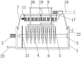
fig. 1 is a schematic view of the front cross-sectional structure of the present invention;
FIG. 2 is a schematic top view of the cross-sectional structure of the sucker cleaning clip of the present invention;
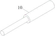
fig. 3 is the structure schematic diagram of the hydraulic telescopic rod of the utility model.
In the figure: 1. a filtration tank; 2. a drive motor; 3. a central tube; 4. a fiber turntable; 5. a suction cup is sucked reversely; 6. a sewage draining support frame; 7. stabilizing the support frame; 8. a sliding connection frame; 9. a cleaning clip support frame; 10. a hydraulic telescopic rod; 11. a motor; 12. cleaning the rotating disc of the clamp; 13. a sucker cleaning clamp; 14. a cleaning clip connecting shaft; 15. a roller support frame; 16. a decontamination drum; 17. a sewage draining hose; 18. a main sewer; 19. a hydraulic cylinder; 20. a telescopic connecting frame; 21. a separator plate; 22. a water inlet pipe; 23. and a water discharge pipe.
Detailed Description
The technical solutions in the embodiments of the present invention will be described clearly and completely with reference to the accompanying drawings in the embodiments of the present invention, and it is obvious that the described embodiments are only some embodiments of the present invention, not all embodiments. Based on the embodiments in the present invention, all other embodiments obtained by a person skilled in the art without creative work belong to the protection scope of the present invention.
Example 1
Referring to fig. 1-3, the present invention provides the following technical solutions: a reverse suction device of a fiber rotary disc filter comprises a filter tank 1, a stable support frame 7 is lapped at the top of the filter tank 1, a sliding connection frame 8 is fixedly connected to the lower surface of the stable support frame 7, a cleaning clamp support frame 9 is movably connected to the inside of the sliding connection frame 8, a hydraulic telescopic rod 10 is fixedly connected to one side of the inside of the sliding connection frame 8, the output end of the hydraulic telescopic rod 10 is fixedly connected to the back of the cleaning clamp support frame 9, a motor 11 is fixedly connected to one side of the cleaning clamp support frame 9, the output end of the motor 11 extends to the inside of the cleaning clamp support frame 9 and is fixedly connected with a cleaning clamp rotating disc 12, a sucker cleaning clamp 13 is movably connected to the inside of the cleaning clamp support frame 9, a cleaning clamp connecting shaft 14 is fixedly connected to one side of a cleaning clamp rotating disc 12, the other end of the cleaning clamp connecting shaft 14 is fixedly connected with, the inside of the drum support frame 15 is provided with a soil removal drum 16.
In this embodiment: the cleaning clamp support frame 9 can slide in the inside of the sliding connection frame 8, the roller support frame 15 sets up the inside of the sucking disc cleaning clamp 13 in a rectangular array mode, a gap is formed between the roller support frame 15 and the roller support frame 15, the hydraulic telescopic rod 10 is operated by the aid of the driving mechanism, the cleaning clamp support frame 9 can be pushed to slide in the sliding connection frame 8, the roller support frame 15 is made to slide to the two sides of the reverse sucking disc 5, then the motor 11 is made to operate, the motor 11 can drive the cleaning clamp rotating disc 12 to rotate after operating, the cleaning clamp rotating disc 12 can drive the sucking disc cleaning clamp 13 to shake to a small extent in a rotating process, and the sucking disc cleaning clamp 13 can drive the decontamination roller 16 to clean up dirt on the surface of the reverse sucking disc 5 in a shaking process.
Specifically, reverse suction suckers 5 are arranged on two sides of the top of the fiber rotating disc 4, and a sewage discharge branch pipe is fixedly connected to the tops of the reverse suction suckers 5.
In this embodiment: the filter cloth in the fiber rotary disc 4 contains a large amount of impurities, so that the back suction sucker 5 can back flush the impurities on the filter cloth and suck the impurities into the sewage branch pipe.
Specifically, the sewage branch pipe penetrates through the inside of the sewage support frame 6 and is fixedly connected with the sewage hose 17, and the top of the sewage support frame 6 is fixedly connected with the sewage hose.
In this embodiment: the sewage draining support frame 6 plays a firm role in the sewage draining branch pipe, and the sewage draining support frame 6 can drive the sewage draining branch pipe to lift simultaneously in the lifting process.
In this embodiment: impurities in the sewage branch pipe are discharged through the sewage hose 17.
Specifically, one end of the sewage hose 17 is fixedly connected with the sewage main pipe 18, and a sewage pump is arranged on one side of the sewage main pipe 18.
In this embodiment: after the sewage pump is operated, impurities in the sewage hose 17 can be pumped into the sewage main pipe 18 and then discharged through the sewage main pipe 18.
Specifically, the top fixedly connected with hydraulic cylinder 19 of firm support frame 7, the output fixedly connected with flexible link 20 of hydraulic cylinder 19, the bottom of flexible link 20 extend to in the filtering ponds 1 and with blowdown support frame 6 fixed connection.
In this embodiment; after the hydraulic cylinder 19 operates, the telescopic connecting frame 20 can be driven to enable the sewage discharge supporting frame 6 to move up and down, so that the reverse suction sucker 5 can ascend or descend.
Specifically, one side of filtering ponds 1 is provided with driving motor 2, and driving motor 2's output extends to filtering ponds 1's inside and with center tube 3 fixed connection, and the surface of center tube 3 has cup jointed fibre carousel 4, and the inside of fibre carousel 4 is provided with the fibre filter cloth.
In this embodiment: thereby driving motor 2 operation back can drive center tube 3 and make fibre carousel 4 rotate and filter the sewage in the filtering ponds 1, and the fibre filter cloth can improve the filter effect to sewage.
Specifically, one side fixedly connected with division board 21 inside filtering ponds 1, one side of filtering ponds 1 is provided with inlet tube 22, and one side that inlet tube 22 was kept away from to filtering ponds 1 is provided with drain pipe 23.
In this embodiment; the partition board 21 can divide the filtering tank 1 into a sewage tank and a clean water tank, after sewage enters the sewage tank through the water inlet pipe 22, the sewage is filtered through the fiber rotating disc 4, and after the sewage is filtered, the sewage flows into the clean water tank through the central pipe 3 and then is discharged through the water discharge pipe 23.
The utility model discloses a theory of operation and use flow: the stable support frame 7 can be lifted after the hydraulic cylinder 19 is operated, the sewage discharge support frame 6 can be driven to move the reverse suction sucker 5 upwards in the lifting process, the cleaning clamp support frame 9 can be moved forwards to the outside of the reverse suction sucker 5 through the hydraulic telescopic rod 10 after the reverse suction sucker 5 is moved upwards, then the motor 11 is operated, the motor 11 can drive the cleaning clamp rotating disc 12 to rotate after the motor 11 is operated, the cleaning clamp rotating disc 12 can drive the sucker cleaning clamp 13 to shake to a small extent in the rotating process, the sucker cleaning clamp 13 can drive the decontamination roller 16 to clean dirt on the surface of the reverse suction sucker 5 in the shaking process, when the reverse suction sucker 5 is moved downwards to two sides of the fiber rotating disc 4 through the hydraulic cylinder 19, the reverse suction sucker 5 is operated through the sewage discharge pump, so that impurities on the surface of the filter cloth are sucked into the sewage discharge branch pipe, and then out through the blowdown header 18.
Finally, it should be noted that: although the present invention has been described in detail with reference to the foregoing embodiments, it will be apparent to those skilled in the art that modifications may be made to the embodiments described in the foregoing embodiments, or equivalents may be substituted for elements thereof. Any modification, equivalent replacement, or improvement made within the spirit and principle of the present invention should be included in the protection scope of the present invention.
Claims (7)
1. The utility model provides a fibre carousel filter anti-suction device, includes filtering ponds (1), its characterized in that: the top overlap joint of filtering ponds (1) has firm support frame (7), the lower fixed surface of firm support frame (7) is connected with sliding connection frame (8), the inside swing joint of sliding connection frame (8) has clean clamp support frame (9), one side fixedly connected with hydraulic telescoping rod (10) of sliding connection frame (8) inside, the output fixed connection of hydraulic telescoping rod (10) is at the back of clean clamp support frame (9), one side fixedly connected with motor (11) of clean clamp support frame (9), the output of motor (11) extends to the inside of clean clamp support frame (9) and with clean clamp rolling disc (12) fixed connection, the inside swing joint of clean clamp support frame (9) has the clean clamp (13) of sucking disc, one side fixedly connected with of clean clamp rolling disc (12) presss from both sides connecting axle (14), the other end of the cleaning clamp connecting shaft (14) is fixedly connected with the sucker cleaning clamp (13), the inside of the sucker cleaning clamp (13) is fixedly connected with a roller supporting frame (15), and a decontamination roller (16) is arranged inside the roller supporting frame (15).
2. A fiber rotary disc filter anti-suction device according to claim 1, wherein: the two sides of the top of the fiber rotating disc (4) are provided with reverse suction suckers (5), and the top of each reverse suction sucker (5) is fixedly connected with a sewage discharge branch pipe.
3. A fiber rotary disc filter anti-suction device according to claim 2, wherein: the sewage branch pipe penetrates through the inside of the sewage support frame (6) and is fixedly connected with the sewage hose (17), and the top of the sewage support frame (6) is fixedly connected with the sewage hose (17).
4. A fiber rotary disc filter anti-suction device according to claim 3, wherein: one end of the sewage discharge hose (17) is fixedly connected with the sewage discharge main pipe (18), and a sewage discharge pump is arranged on one side of the sewage discharge main pipe (18).
5. A fiber rotary disc filter anti-suction device according to claim 1, wherein: the top fixedly connected with hydraulic cylinder (19) of firm support frame (7), the output fixedly connected with flexible link (20) of hydraulic cylinder (19), the bottom of flexible link (20) extend to in filtering ponds (1) and with blowdown support frame (6) fixed connection.
6. A fiber rotary disc filter anti-suction device according to claim 1, wherein: one side of filtering ponds (1) is provided with driving motor (2), the output of driving motor (2) extend to the inside of filtering ponds (1) and with center tube (3) fixed connection, fiber carousel (4) has been cup jointed to the surface of center tube (3), the inside of fiber carousel (4) is provided with the fibre filter cloth.
7. A fiber rotary disc filter anti-suction device according to claim 1, wherein: one side fixedly connected with division board (21) of filtering ponds (1) inside, one side of filtering ponds (1) is provided with inlet tube (22), one side that inlet tube (22) were kept away from in filtering ponds (1) is provided with drain pipe (23).
Priority Applications (1)
| Application Number | Priority Date | Filing Date | Title |
|---|---|---|---|
| CN201920722892.4U CN210543707U (en) | 2019-05-20 | 2019-05-20 | Reverse suction device of fiber rotary disc filter |
Applications Claiming Priority (1)
| Application Number | Priority Date | Filing Date | Title |
|---|---|---|---|
| CN201920722892.4U CN210543707U (en) | 2019-05-20 | 2019-05-20 | Reverse suction device of fiber rotary disc filter |
Publications (1)
| Publication Number | Publication Date |
|---|---|
| CN210543707U true CN210543707U (en) | 2020-05-19 |
Family
ID=70666140
Family Applications (1)
| Application Number | Title | Priority Date | Filing Date |
|---|---|---|---|
| CN201920722892.4U Active CN210543707U (en) | 2019-05-20 | 2019-05-20 | Reverse suction device of fiber rotary disc filter |
Country Status (1)
| Country | Link |
|---|---|
| CN (1) | CN210543707U (en) |
Cited By (2)
| Publication number | Priority date | Publication date | Assignee | Title |
|---|---|---|---|---|
| CN111905440A (en) * | 2020-09-14 | 2020-11-10 | 刘文宏 | Papermaking wastewater filtering device |
| CN113941454A (en) * | 2021-09-29 | 2022-01-18 | 复旦大学附属肿瘤医院 | Centrifugal device and centrifugal method for collecting Cyr61 target conditioned medium |
-
2019
- 2019-05-20 CN CN201920722892.4U patent/CN210543707U/en active Active
Cited By (3)
| Publication number | Priority date | Publication date | Assignee | Title |
|---|---|---|---|---|
| CN111905440A (en) * | 2020-09-14 | 2020-11-10 | 刘文宏 | Papermaking wastewater filtering device |
| CN113941454A (en) * | 2021-09-29 | 2022-01-18 | 复旦大学附属肿瘤医院 | Centrifugal device and centrifugal method for collecting Cyr61 target conditioned medium |
| CN113941454B (en) * | 2021-09-29 | 2023-06-30 | 复旦大学附属肿瘤医院 | Centrifugal device and centrifugal method for collecting Cyr61 target spot conditioned medium |
Similar Documents
| Publication | Publication Date | Title |
|---|---|---|
| CN210543707U (en) | Reverse suction device of fiber rotary disc filter | |
| CN110449426A (en) | A kind for the treatment of tank mud clearing and retrieving device | |
| CN113144729A (en) | Efficient circulating desanding device for sewage treatment and using method thereof | |
| CN109750649A (en) | A kind of sundries cleaning device of garden landscape circulating water pool | |
| CN212214810U (en) | Sewage treatment equipment convenient for sundries cleaning | |
| CN201959611U (en) | Fixed square plate type filter | |
| CN218188427U (en) | Urban sewage deep purification treatment V-shaped filter | |
| CN115531938A (en) | Water conservancy project water treatment facilities | |
| CN213313645U (en) | Multistage filter device for wastewater treatment | |
| CN210108676U (en) | Experimental water pool with towing device | |
| CN208878076U (en) | A kind of strainer trash | |
| CN209899279U (en) | Plane hydrops aspirator | |
| CN113830923A (en) | Underground environment-friendly water treatment equipment and using method | |
| CN209438157U (en) | A kind of self-cleaning filter | |
| CN113262548A (en) | Efficient flocculate separating device for chemical sewage treatment | |
| CN214106061U (en) | Fiber rotary disc filter for treating oily sewage | |
| CN219156637U (en) | Water conservancy hydropower construction drainage device | |
| CN220125618U (en) | Swimming pool hydrologic cycle water purification treatment facilities | |
| CN219195794U (en) | Waterproof drainage device for water conservancy construction | |
| CN114772778B (en) | Building construction drainage device | |
| CN217924056U (en) | Municipal administration sewage aftertreatment silt remover | |
| CN218901000U (en) | Sewage draining device for water treatment | |
| CN219701336U (en) | Forced circulation separator for sewage treatment | |
| CN219860811U (en) | MBR membrane sewage treatment device | |
| CN217710513U (en) | Highway road surface drainage water-collecting device |
Legal Events
| Date | Code | Title | Description |
|---|---|---|---|
| GR01 | Patent grant | ||
| GR01 | Patent grant | ||
| TR01 | Transfer of patent right |
Effective date of registration: 20231222 Address after: 443000, No. 3 Xingye 1st Road, Industrial Park, High speed Railway North Station, Economic Development Zone, Yiling District, Yichang City, Hubei Province Patentee after: Dachu Environmental Protection (Hubei) Co.,Ltd. Address before: 443100 Yixing Avenue, Yiling District, Yichang City, Hubei Province Patentee before: HUBEI JINSHUNXIANG ENVIRONMENTAL PROTECTION Co.,Ltd. |
|
| TR01 | Transfer of patent right |