CN210531618U - Pneumatic stop valve for high-pressure oxygen - Google Patents
Pneumatic stop valve for high-pressure oxygen Download PDFInfo
- Publication number
- CN210531618U CN210531618U CN201921389338.5U CN201921389338U CN210531618U CN 210531618 U CN210531618 U CN 210531618U CN 201921389338 U CN201921389338 U CN 201921389338U CN 210531618 U CN210531618 U CN 210531618U
- Authority
- CN
- China
- Prior art keywords
- valve
- pressure oxygen
- monel
- pneumatic stop
- valve body
- Prior art date
- Legal status (The legal status is an assumption and is not a legal conclusion. Google has not performed a legal analysis and makes no representation as to the accuracy of the status listed.)
- Active
Links
Images


Abstract
The utility model discloses a pneumatic stop valve for high-pressure oxygen, including valve body, valve gap, valve clack subassembly, valve rod and double-acting cylinder etc. mainly be with the embedded Monel internals of installation in the runner valve pocket of valve body, and through this Monel internals and high-pressure oxygen contact, in order to guarantee the safe in utilization of high-pressure oxygen operating mode, then whole valve body itself just can adopt the stainless steel forging that use intensity is great, and such combined structure compares that the valve body all adopts Monel forging, has both reached the required use intensity of valve, can not improve manufacturing cost again; meanwhile, a high-pressure spring energy storage sealing ring fixed by a pressure plate is additionally arranged between the bottom of the valve cover and the valve rod, so that the packing in the lifting process of the valve rod can be prevented from leaking on the basis of using common valve packing, and the use is more reliable; in addition, a double-acting air cylinder is designed as an actuating mechanism, so that remote control of opening and closing of the valve can be realized, and the safety of personnel is guaranteed.
Description
Technical Field
The utility model relates to a pneumatic stop valve, in particular to a pneumatic stop valve for high-pressure oxygen.
Background
The stop valve special for high-pressure oxygen has the advantages of high mechanical strength, abrasion resistance, good safety and the like, can be widely applied to oxygen pipelines, achieves better explosion-proof flame-retardant function, and can eliminate unsafe factors on the oxygen pipelines. The special stop valve for the high-pressure oxygen is used as opening and closing equipment on an oxygen conveying pipeline in the metallurgical industry, and has more severe requirements compared with other general valves, and because the oxygen belongs to flammable and explosive dangerous goods, leakage, static and spark are prevented, so that the structural design must ensure that a runner valve cavity for flowing the high-pressure oxygen in the valve body is preferably contacted by adopting corrosion-resistant alloy of Monel material, but the Monel material cost is higher, if the valve body is integrally made of the Monel forge piece, the use strength of the stainless steel forge piece cannot be realized, and the production cost is higher; meanwhile, when the valve clack of the special stop valve for high-pressure oxygen is opened and closed, the valve rod of the driving valve clack only goes up and down without rolling, so that the abrasion of sealing materials such as packing can be effectively reduced, but the packing is installed at the top of the valve cover in a sealing mode through the gland, structural sealing is not carried out between the bottom of the valve cover and the valve rod, and then the packing is leaked from the position in the lifting process of the valve rod, so that the use reliability is influenced.
Disclosure of Invention
The utility model aims to solve the technical problem that overcome prior art's defect and provide one kind and guaranteeing under the prerequisite of high-pressure oxygen operating mode safety in utilization, both reached the required use intensity of valve, can not improve manufacturing cost again, but also can eliminate the filler leakage in the use, use the pneumatic stop valve for high-pressure oxygen of reliability more.
The technical problem of the utility model is realized through following technical scheme:
the utility model provides a pneumatic stop valve for high-pressure oxygen, includes valve body, the runner valve pocket and the valve clack subassembly in the valve body, the valve gap of valve body top seal installation, the valve rod of lift movable seal installation in the valve gap and the double-acting cylinder of valve gap top fixed mounting, double-acting cylinder drive valve rod and drive the valve clack subassembly and make the lift activity, the runner valve pocket in be equipped with the Monel internals of embedded installation, this Monel internals middle part is equipped with the through-hole, installs the valve clack subassembly in the Monel internals, and the valve clack subassembly is done the lift activity by the valve rod drive and is sealed open and close this through-hole.
The flow passage valve cavity is a T-shaped cavity, the T-shaped cavity is formed by a vertical cavity axially penetrating through the valve body and a side cavity transversely communicated with the vertical cavity, a lower port of the vertical cavity is set as an outlet end, and an outer port of the side cavity is set as an inlet end.
The Monel inner part is a T-shape pipe which is completely embedded and attached in the flow channel valve cavity, and the T-shape pipe is composed of a vertical pipe and a horizontal pipe, wherein the axis of the vertical pipe is overlapped with the vertical cavity, and the axis of the horizontal pipe is overlapped with the side cavity; the through hole is an inner shoulder hole arranged in the vertical pipe.
And a high-pressure spring energy storage sealing ring is arranged between the bottom of the valve cover and the valve rod, and a pressing plate for installing and fixing the high-pressure spring energy storage sealing ring is arranged on the bottom surface of the valve cover.
The inlet end is provided with an inlet flange which is installed in a sealing mode, the outlet end is provided with an outlet flange which is installed in a sealing mode, and the inlet flange and the outlet flange are both annular flanges.
And red copper lens gaskets are arranged between the inlet flange and the inlet end and between the outlet flange and the outlet end.
And a packing is arranged between the top of the valve cover and the valve rod, and a gland for sealing the packing is arranged on the top surface of the valve cover.
And connecting blocks which are mutually connected are arranged between the cylinder rod of the double-acting air cylinder and the upper end of the valve rod.
The double-acting cylinder is fixedly arranged on the top of the valve cover through a connecting support.
And a red copper lens gasket is arranged between the valve cover and the valve body.
Compared with the prior art, the utility model mainly arranges the Monel inner part which is embedded in the flow passage valve cavity of the valve body and contacts with the high-pressure oxygen through the Monel inner part to ensure the use safety of the working condition of the high-pressure oxygen, so that the whole valve body can adopt the stainless steel forging with larger use strength, compared with the combined structure that the valve body adopts the Monel forging, the use strength required by the valve is achieved, and the production cost is not increased; meanwhile, a high-pressure spring energy storage sealing ring fixed by a pressure plate is additionally arranged between the bottom of the valve cover and the valve rod, so that the packing in the lifting process of the valve rod can be prevented from leaking on the basis of using common valve packing, and the use is more reliable; in addition, a double-acting air cylinder is designed as an actuating mechanism, so that remote control of opening and closing of the valve can be realized, and the safety of personnel is guaranteed.
Drawings
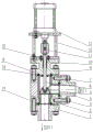
Fig. 1 is a schematic sectional view of the present invention.
Fig. 2 is a schematic structural view of fig. 1 with the valve cover, connecting bracket and double acting cylinder removed.
Fig. 3 is a perspective view of fig. 2.
Detailed Description
The embodiments of the present invention will be described in detail below with reference to the drawings.
As shown in fig. 1 to 3, the valve comprises an outlet flange 1, a valve body 2, a monel internal part 3, a standpipe 31, a transverse pipe 32, a through hole 33, an inlet flange 4, a valve clack component 5, a valve rod 6, a pressure plate 7, a high-pressure spring energy storage sealing ring 8, a valve cover 9, a filler 10, a connecting block 11, a connecting bracket 12, a double-acting cylinder 13, a red copper lens gasket 14, and a gland 15.
A pneumatic stop valve for high-pressure oxygen is mainly composed of a valve body 2, a valve cover 9, a valve clack assembly 5, a valve rod 6, a double-acting cylinder 13 and the like, as shown in figure 1.
The whole valve body 2 is made of a stainless steel forging with high strength, a T-shape flow channel valve cavity is arranged in the valve body 2, the T-shape cavity is composed of a vertical cavity axially penetrating through the valve body 2 and a side cavity transversely communicating with the vertical cavity as shown in figure 1, a lower port of the vertical cavity is set as an outlet end, an upper port of the vertical cavity is used for the valve rod 6 to be installed, and an outer port of the side cavity is set as an inlet end.
The inlet end be equipped with seal installation's import flange 4, the exit end is equipped with seal installation's export flange 1, this import flange 4 all adopts as shown in fig. 2, fig. 3 with export flange 1 to all be equipped with red copper lens gasket 14 between import flange 4 and the inlet end, between export flange 4 and the exit end, rethread bolt is with import flange 4 and export flange 1 connection on valve body 2, can guarantee the reliability of connecting under the high pressure oxygen operating mode like this.
A Monel inner part 3 which is embedded and installed is arranged in the flow passage valve cavity, the Monel inner part is designed into a T-shape tube which can be completely embedded and attached in the flow passage valve cavity, and the T-shape tube is composed of a vertical tube 31 of which the axis is overlapped with the vertical cavity and a horizontal tube 32 of which the axis is overlapped with the side cavity; therefore, the high-pressure oxygen enters the valve body 2 from the inlet end and is in direct contact with the Monel corrosion-resistant alloy, the use safety of the working condition of the high-pressure oxygen can be better ensured, and compared with the combined structure of the valve body 2 of the stainless steel forged piece and the Monel inner piece 3, the combined structure of the valve body 2 and the Monel inner piece adopts the Monel forged piece, so that the use strength required by the valve is achieved, and the production cost cannot be increased.
The Monel inner member 3 is provided with a through hole 33 in the middle, the through hole is an inner shoulder hole arranged in the vertical pipe 31, the position of the through hole is just below the joint of the vertical pipe 31 and the transverse pipe 32, and the Monel inner member 3 is also provided with a valve flap assembly 5 which can realize sealing opening and closing matching with the through hole 33.
The valve cover 9 is hermetically arranged at the top of the valve body 2, the valve cover 9 just seals the upper port of the valve body 2, a red copper lens gasket 14 is also arranged between the valve cover 9 and the valve body 2, and a double-acting cylinder 13 serving as an actuating mechanism is fixedly arranged at the top of the valve cover 9 through a connecting support 12.
Valve rod 6 lift movable seal install in valve gap 9, specific mounting structure is: a packing 10 is arranged between the top of the valve cover 9 and the valve rod 6 as a dynamic sealing element, and the top surface of the valve cover 9 is provided with a gland 15 for sealing the packing 10; a high-pressure spring energy storage sealing ring 8 is arranged between the bottom of the valve cover 9 and the valve rod 6, and a pressing plate 7 for installing and fixing the high-pressure spring energy storage sealing ring 8 is arranged on the bottom surface of the valve cover 9. Through the structural design, the sealing of the lifting activity of the valve rod 6 is ensured, and the packing 10 in the lifting process of the valve rod can be prevented from leaking on the basis of using common valve packing, so that the use is more reliable.
The lower end of the valve rod 6 extends out of the bottom of the valve cover 9 and is connected with the valve clack assembly 5 in the Monel inner part 3, the upper end of the valve rod 6 extends out of the top of the valve cover 9 and is connected with a cylinder rod of the double-acting cylinder 13 through the connecting block 11, and then the double-acting cylinder 13 can drive the valve rod 6 and drive the valve clack assembly 5 to move up and down, so that the through hole 33 in the Monel inner part 3 is opened and closed in a sealing mode, namely the opening and closing of the.
And the actuating mechanism of the valve adopts a double-acting cylinder 13, so that the remote control of the opening and closing of the valve is realized, and the safety of personnel is ensured.
The above description is only an embodiment of the present invention, and it should be understood by those skilled in the art that any structural design equivalent to this embodiment is included in the scope of the present invention.
Claims (10)
1. The utility model provides a pneumatic stop valve for high-pressure oxygen, includes valve body (2), the runner valve pocket and valve flap subassembly (5) in the valve body, valve gap (9) of valve body (2) top seal installation, valve rod (6) and valve gap (9) top fixed mounting's two effect cylinder (13) of lift movable seal installation in the valve gap, two effect cylinder (13) drive valve rod (6) and drive valve flap subassembly (5) and make the lift activity, its characterized in that the runner valve pocket in be equipped with embedded installation Monel (3), this Monel internals middle part is equipped with through-hole (33), installs valve flap subassembly (5) in Monel internals (3), and valve flap subassembly is driven by valve rod (6) and is made the lift activity and seal and open and close this through-hole (33).
2. The pneumatic stop valve for high pressure oxygen of claim 1, wherein the runner valve chamber is a T-shape chamber, the T-shape chamber is composed of a vertical chamber axially passing through the valve body (2) and a side chamber transversely passing through the vertical chamber, the lower port of the vertical chamber is an outlet port, and the outer port of the side chamber is an inlet port.
3. The pneumatic stop valve for high pressure oxygen of claim 2, wherein the monel inner member (3) is a T-shape tube which is completely embedded in the flow passage valve cavity, and the T-shape tube is composed of a vertical tube (31) with an axial line overlapped with the vertical cavity and a horizontal tube (32) with an axial line overlapped with the side cavity; the through hole (33) is an inner shoulder hole arranged in the vertical pipe (31).
4. The pneumatic stop valve for high-pressure oxygen according to claim 1, wherein a high-pressure spring energy-storage sealing ring (8) is arranged between the bottom of the valve cover (9) and the valve rod (6), and a pressing plate (7) for installing and fixing the high-pressure spring energy-storage sealing ring (8) is arranged on the bottom surface of the valve cover (9).
5. A pneumatic stop valve for high pressure oxygen as claimed in claim 2, wherein the inlet end is provided with a sealingly mounted inlet flange (4) and the outlet end is provided with a sealingly mounted outlet flange (1), both the inlet flange (4) and the outlet flange (1) being annular flanges.
6. The pneumatic stop valve for high pressure oxygen of claim 5, wherein red copper lens gaskets (14) are respectively arranged between the inlet flange (4) and the inlet end and between the outlet flange (1) and the outlet end.
7. A pneumatic stop valve for high pressure oxygen as claimed in claim 1, wherein a packing (10) is provided between the top of the valve cover (9) and the valve stem (6), and a gland (15) for sealing the packing (10) is provided on the top of the valve cover (9).
8. A pneumatic stop valve for high pressure oxygen as claimed in claim 1, wherein the double acting cylinder (13) has a connecting piece (11) interconnecting the cylinder rod and the upper end of the valve stem (6).
9. A pneumatic stop valve for high pressure oxygen as claimed in claim 8, wherein the double acting cylinder (13) is fixedly mounted on top of the valve cover (9) via a connecting bracket (12).
10. The pneumatic stop valve for high-pressure oxygen of claim 8, characterized in that a red copper lens gasket (14) is arranged between the valve cover (9) and the valve body (2).
Priority Applications (1)
| Application Number | Priority Date | Filing Date | Title |
|---|---|---|---|
| CN201921389338.5U CN210531618U (en) | 2019-08-26 | 2019-08-26 | Pneumatic stop valve for high-pressure oxygen |
Applications Claiming Priority (1)
| Application Number | Priority Date | Filing Date | Title |
|---|---|---|---|
| CN201921389338.5U CN210531618U (en) | 2019-08-26 | 2019-08-26 | Pneumatic stop valve for high-pressure oxygen |
Publications (1)
| Publication Number | Publication Date |
|---|---|
| CN210531618U true CN210531618U (en) | 2020-05-15 |
Family
ID=70602967
Family Applications (1)
| Application Number | Title | Priority Date | Filing Date |
|---|---|---|---|
| CN201921389338.5U Active CN210531618U (en) | 2019-08-26 | 2019-08-26 | Pneumatic stop valve for high-pressure oxygen |
Country Status (1)
| Country | Link |
|---|---|
| CN (1) | CN210531618U (en) |
Cited By (1)
| Publication number | Priority date | Publication date | Assignee | Title |
|---|---|---|---|---|
| CN114165603A (en) * | 2021-02-24 | 2022-03-11 | 常德翔宇设备制造有限公司 | Special stop valve for oxygen |
-
2019
- 2019-08-26 CN CN201921389338.5U patent/CN210531618U/en active Active
Cited By (1)
| Publication number | Priority date | Publication date | Assignee | Title |
|---|---|---|---|---|
| CN114165603A (en) * | 2021-02-24 | 2022-03-11 | 常德翔宇设备制造有限公司 | Special stop valve for oxygen |
Similar Documents
| Publication | Publication Date | Title |
|---|---|---|
| CN207018556U (en) | Can on-line maintenance upper dress flat gate valve | |
| WO2018153203A1 (en) | Electric fluorine-lined corrugated pipe single-seat regulating valve | |
| CN210531618U (en) | Pneumatic stop valve for high-pressure oxygen | |
| CN111237486A (en) | Forged steel oxygen stop valve | |
| CN206361185U (en) | A kind of cryogenic ball valve | |
| CN205937894U (en) | Corrugated pipe stop valve for chlorine | |
| CN203272811U (en) | Internal pressure corrugated pipe stop valve with opening and closing position display | |
| CN2416290Y (en) | Cone seal stop valve for liquid caustic soda | |
| CN210949952U (en) | Ultra-high pressure guide plate flat gate valve | |
| CN210715963U (en) | Double-cutoff self-sealing high-pressure stop valve | |
| CN203009855U (en) | Internal-pressure self-sealing type valve cover stop valve | |
| CN203309137U (en) | Y-shaped heat-insulating stop valve | |
| CN201487240U (en) | Full sealed zero leakage stop valve | |
| CN201651333U (en) | Special valve for chlorine gas | |
| WO2018152947A1 (en) | Pneumatic fluorine-lined corrugated pipe single-seat regulating valve | |
| CN219570861U (en) | Special angular corrugated pipe sealing single-seat control valve | |
| CN2343423Y (en) | Fluoroplastic full-lining stop valve for chlor-alkali | |
| CN210600226U (en) | Double-cutoff bottom valve | |
| CN219755355U (en) | Pneumatic stop valve | |
| CN203627835U (en) | Corrugated pipe discharge valve with corrugated pipe protecting sleeve | |
| CN203880130U (en) | Fixed ball valve for top assembling | |
| CN216519697U (en) | High-temperature high-pressure dual self-sealing electric gate valve | |
| CN2409389Y (en) | Three-position two-way piston valve | |
| CN108426038A (en) | A kind of high-pressure resistant corrugated pipe shut-off valve | |
| CN210800072U (en) | Flange type stop valve with sealing ring gasket on flange surface |
Legal Events
| Date | Code | Title | Description |
|---|---|---|---|
| GR01 | Patent grant | ||
| GR01 | Patent grant |