CN210511916U - Indoor unit of air conditioner - Google Patents
Indoor unit of air conditioner Download PDFInfo
- Publication number
- CN210511916U CN210511916U CN201921519843.7U CN201921519843U CN210511916U CN 210511916 U CN210511916 U CN 210511916U CN 201921519843 U CN201921519843 U CN 201921519843U CN 210511916 U CN210511916 U CN 210511916U
- Authority
- CN
- China
- Prior art keywords
- indoor unit
- fresh air
- air
- air conditioner
- fresh
- Prior art date
- Legal status (The legal status is an assumption and is not a legal conclusion. Google has not performed a legal analysis and makes no representation as to the accuracy of the status listed.)
- Active
Links
- 238000004378 air conditioning Methods 0.000 claims abstract description 25
- 238000004891 communication Methods 0.000 claims description 4
- 238000000034 method Methods 0.000 claims 1
- 238000009792 diffusion process Methods 0.000 description 5
- 238000009434 installation Methods 0.000 description 4
- RYGMFSIKBFXOCR-UHFFFAOYSA-N Copper Chemical compound [Cu] RYGMFSIKBFXOCR-UHFFFAOYSA-N 0.000 description 2
- 238000003915 air pollution Methods 0.000 description 2
- 230000008859 change Effects 0.000 description 2
- 229910052802 copper Inorganic materials 0.000 description 2
- 239000010949 copper Substances 0.000 description 2
- 230000002349 favourable effect Effects 0.000 description 2
- 238000003905 indoor air pollution Methods 0.000 description 2
- 230000004048 modification Effects 0.000 description 2
- 238000012986 modification Methods 0.000 description 2
- 239000000779 smoke Substances 0.000 description 2
- 230000008901 benefit Effects 0.000 description 1
- 238000004140 cleaning Methods 0.000 description 1
- 230000008094 contradictory effect Effects 0.000 description 1
- 230000008878 coupling Effects 0.000 description 1
- 238000010168 coupling process Methods 0.000 description 1
- 238000005859 coupling reaction Methods 0.000 description 1
- 238000005034 decoration Methods 0.000 description 1
- 230000000694 effects Effects 0.000 description 1
- 238000005516 engineering process Methods 0.000 description 1
- 230000036541 health Effects 0.000 description 1
- 239000000463 material Substances 0.000 description 1
- 239000003973 paint Substances 0.000 description 1
- 230000008092 positive effect Effects 0.000 description 1
- 239000002341 toxic gas Substances 0.000 description 1
Images


Landscapes
- Air Filters, Heat-Exchange Apparatuses, And Housings Of Air-Conditioning Units (AREA)
Abstract
The utility model provides an air-conditioning indoor unit, which comprises an electric control box (3), a heat exchanger (2), a base (24) and a shell combined with the base (24); the heat exchanger (2) is arranged in the shell, and the heat exchanger (2) comprises a connecting end (6) connected with an outdoor unit; the shell and the base (24) jointly define a mounting cavity for accommodating the electric control box (3), and the electric control box (3) is positioned on one side of the connecting end (6) of the heat exchanger (2); the air-conditioning indoor unit (1) comprises a fresh air device (7), wherein the fresh air device (7) is arranged outside the air-conditioning indoor unit (1) and is positioned at the top of the electric control box (3); the fresh air device (7) comprises a fresh air outlet (15) facing the front side of the indoor unit of the air conditioner; the utility model provides an indoor unit of air conditioner, it sets up the top of new trend device in the indoor unit of air conditioner, does not occupy the inner space of indoor unit of air conditioner, effectively reduces the influence to the size of indoor unit of air conditioner.
Description
Technical Field
The utility model belongs to the technical field of the air conditioner, especially, relate to an indoor unit of air conditioner.
Background
When the industry is rapidly developed, the population is extremely rapidly increased, an environment and human crisis is hidden behind the flourishing, the air pollution seriously threatens the health of people, and more than 70 percent of the time is spent indoors for people living in cities in particular. Research shows that indoor air pollution far exceeds outdoor air pollution: outdoor dirty air in haze weather enters the room through doors and windows, and toxic gas continuously emitted by indoor decoration materials, paint, furniture and the like is gathered indoors, so that second-hand smoke, kitchen oil smoke and the like pollute the indoor air, and the indoor air pollution is more than 5 times more serious than that outdoors. Therefore, a fresh air and air conditioner integrated machine is arranged in the prior art to adjust the temperature of indoor air and perform cleaning treatment, so that the quality of the indoor air is improved.
At present, the current fresh air device of on-hook mostly sets up the tip at the indoor set to be located the inside of indoor set completely, current fresh air device occupies the tip space of indoor set, leads to indoor set length to be long partially under the structure setting of guaranteeing the new trend air supply volume, is unfavorable for the size of control indoor set.
In view of this, the present invention is proposed.
Disclosure of Invention
The utility model discloses to foretell technical problem, provide an indoor unit of air conditioner.
In order to achieve the above object, the utility model discloses a technical scheme be:
the air-conditioning indoor unit comprises an electric control box, a heat exchanger, a base and a shell combined with the base; the heat exchanger is arranged in the shell and comprises a connecting end connected with the outdoor unit; the shell and the base jointly define an installation cavity for accommodating the electric control box, and the electric control box is positioned on one side of the connecting end of the heat exchanger; the air-conditioning indoor unit comprises a fresh air device, and the fresh air device is arranged outside the air-conditioning indoor unit and is positioned at the top of the electric control box; the fresh air device comprises a fresh air outlet facing the front side of the indoor unit of the air conditioner.
Preferably, the fresh air device comprises a fan module and an air inlet cavity; the air inlet cavity is arranged at the top of the indoor unit of the air conditioner; the fan module is located air inlet chamber top, and is linked together with the air inlet chamber.
Preferably, a fresh air communicating opening is formed in the top of the air inlet cavity; the fan module comprises a fresh air suction inlet; the fresh air suction inlet is connected with the fresh air communication port.
Preferably, the air-conditioning indoor unit comprises a side end plate positioned on one side of the connecting end of the heat exchanger, a gap is formed between the side end plate and the electric control box, and an accommodating groove is formed between the side end plate and a box body of the electric control box.
Preferably, a fresh air pipe interface is arranged in an area, corresponding to the accommodating groove, of the top of the indoor unit of the air conditioner; the fresh air pipe joint corresponds to a fresh air pipe joint at the top of the indoor unit of the air conditioner and penetrates through the fresh air pipe joint to enter the accommodating groove.
Preferably, the fresh air device is covered with an outer cover.
Preferably, a through hole is formed in the bottom of the outer cover and corresponds to the fresh air pipe joint; and a fresh air pipe joint on the fresh air device penetrates through the through hole.
Preferably, the housing comprises a casing; an opening is formed in one end of the housing, and a baffle is arranged outside the opening; the baffle plate is matched with the housing to form an accommodating space for accommodating the fresh air device.
Preferably, the bottom of the fresh air device is provided with a fresh air pipe joint, and the fresh air pipe joint can be connected with a fresh air pipe.
Preferably, the top of the indoor unit of the air conditioner is provided with an air inlet, and the fresh air device is located adjacent to the air inlet.
Compared with the prior art, the utility model discloses an advantage lies in with positive effect:
the utility model provides an air-conditioning indoor unit, which arranges a fresh air device at the top of the air-conditioning indoor unit, does not occupy the inner space of the air-conditioning indoor unit, and effectively reduces the influence on the size of the air-conditioning indoor unit; simultaneously with the new trend air outlet of new trend device towards the front side of air conditioning indoor set to guide new trend to blow to the front of indoor set, be favorable to the diffusion of new trend in indoor, improved user's comfort level.
Drawings
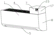
Fig. 1 is a schematic view of the whole structure of the indoor unit of the air conditioner of the present invention;
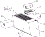
FIG. 2 is an exploded view of the indoor unit of the air conditioner of the present invention;
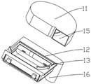
FIG. 3 is a schematic structural view of a fresh air device of the indoor unit of an air conditioner of the present invention;
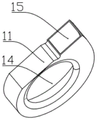
fig. 4 is a schematic structural view of a fan module of the indoor unit of the air conditioner of the present invention;
FIG. 5 is a first schematic view of the structure of the casing of the indoor unit of the air conditioner of the present invention;
FIG. 6 is a second schematic view of the housing structure of the indoor unit of the air conditioner of the present invention;
fig. 7 is a schematic view of a partial structure of an indoor unit of an air conditioner according to the present invention;
fig. 8 is a schematic view of the overall structure of the indoor unit of the air conditioner of the present invention;
fig. 9 is a schematic view of a partial structure of an indoor unit of an air conditioner of the present invention;
fig. 10 is a schematic view of the overall structure of the indoor unit of an air conditioner according to the present invention.
In the above figures: an air-conditioning indoor unit 1; a heat exchanger 2; an electric control box 3; an air inlet 4; an air outlet 5; a connecting end 6; a fresh air device 7; a side end plate 8; a housing tank 9; a fresh air pipe connector 10; a fan module 11; an air inlet cavity 12; a fresh air communication port 13; a fresh air suction inlet 14; a fresh air outlet 15; a fresh air duct joint 16; a housing 17; a housing 18; an opening 20; a baffle plate 21; a through-hole 22; a through hole 23; a base 24.
Detailed Description
The present invention is further described below in conjunction with specific embodiments so that those skilled in the art may better understand the present invention and can implement the present invention, but the scope of the present invention is not limited to the scope described in the detailed description. It should be noted that the embodiments and features of the embodiments in the present application may be arbitrarily combined with each other without conflict.
It should be noted that all directional indicators (such as up, down, left, right, front, and back) in the embodiments of the present invention are only used to explain the relative position relationship between the components, the motion situation, etc. in a specific posture (as shown in the drawings), and if the specific posture is changed, the directional indicator is correspondingly changed accordingly.
In addition, the descriptions related to "first", "second", etc. in the present invention are for descriptive purposes only and are not to be construed as indicating or implying relative importance or implicit ly indicating the number of technical features indicated. Thus, a feature defined as "first" or "second" may explicitly or implicitly include at least one such feature.
In addition, the technical solutions in the embodiments may be combined with each other, but it must be based on the realization of those skilled in the art, and when the technical solutions are contradictory or cannot be realized, the combination of the technical solutions should not be considered to exist, and is not within the protection scope of the present invention.
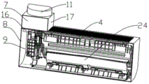
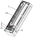
As shown in fig. 1-10, an air-conditioning indoor unit 1 includes an electric control box 3, a heat exchanger 2, a base 24, and a casing combined with the base 24. The top of the indoor air-conditioning unit 1 is provided with an air inlet 4, and the front lower side of the indoor air-conditioning unit 1 is provided with an air outlet 5. The heat exchanger 2 is arranged in the shell; the heat exchanger 2 comprises a connecting end 6, and the copper pipe of the heat exchanger 2 of the indoor unit 1 of the air conditioner and the interface of the copper pipe of the heat exchanger of the outdoor unit are both positioned at the connecting end 6. In this embodiment, the connection end 6 of the indoor unit 1 of the air conditioner is arranged at the right end of the indoor unit 1 of the air conditioner; the shell and the base 24 jointly define a mounting cavity for accommodating the electric control box 3, and the electric control box 3 is mounted on the base 24 and is positioned on one side of the connecting end 6 of the heat exchanger 2.
The electric control box 3 is connected with the base 24 through detachable connecting structures such as screws, buckle structures and the like. As a known technology, the electrical control box 3 has an inner cavity for accommodating electrical control elements of the air conditioner, and the electrical control elements in the electrical control box 3 are connected to electrical devices (such as an air deflector driving motor, a display lamp circuit board, etc.) distributed at various positions of the indoor unit 1 of the air conditioner through wires.
The indoor unit 1 of the air conditioner comprises a fresh air device 7, wherein the fresh air device 7 is arranged at the top of the indoor unit 1 of the air conditioner and corresponds to the position of the electric control box 3. The fresh air device 7 is located at the position adjacent to the air inlet 4 at the top of the indoor air conditioner 1, so that the length and the size of the indoor air conditioner 1 are effectively limited, and meanwhile, the air inlet 4 is not shielded.
The air-conditioning indoor unit 1 comprises a side end plate 8 positioned on one side of the connecting end 6 of the heat exchanger 2, a gap is formed between the side end plate 8 and the electric control box 3, and an accommodating groove 9 is formed between the side end plate 8 and the electric control box 3. A fresh air pipe connector 10 is arranged in the area, corresponding to the accommodating groove 9, of the top of the indoor unit 1 of the air conditioner; namely, the fresh air pipe interface 10 penetrates through the top of the indoor unit 1 of the air conditioner and is communicated with the accommodating groove 9.
The fresh air device 7 comprises a fan module 11 and an air inlet cavity 12. The air inlet cavity 12 is arranged at the top of the indoor unit 1 of the air conditioner; the fan module 11 is located on the top of the air inlet cavity 12 and is communicated with the air inlet cavity 12. And a fresh air communicating opening 13 is formed in the top of the air inlet cavity 12. The fan module 11 comprises a fresh air suction inlet 14 and a fresh air outlet 15; the fresh air suction port 14 corresponds to the fresh air communication port 13 so as to communicate the air inlet cavity 12 with the fan module 11; the fresh air outlet 15 is arranged on the front surface of the indoor unit 1 of the air conditioner, namely, in front of the indoor unit 1 of the air conditioner. The fresh air device is arranged in the indoor unit in the current market, and the fresh air outlet of the fresh air device can be arranged on the top surface, the side surface, the front surface and the lower surface. If the fresh air outlet is arranged on the top surface, because the installation position of the indoor unit is closer to the ceiling, the fresh air blown out from the fresh air outlet is easy to blow to the ceiling, and the diffusion of the fresh air indoors is not facilitated. If the fresh air outlet is arranged on the side face, the diffusion of the fresh air to the other side is not facilitated. If the fresh air outlet is arranged on the front side, an air outlet or an air outlet hole needs to be added on the panel of the indoor unit, and the appearance effect of the panel of the indoor unit is affected. If the fresh air outlet is arranged below, when the fresh air function is used in winter or summer, the fresh air can blow to people, and the people feel uncomfortable. In the embodiment, the fresh air device 7 is arranged at the top of the indoor unit 1 of the air conditioner, so that the internal space of the indoor unit 1 of the air conditioner is not occupied, and the size of the indoor unit 1 of the air conditioner is not affected. In addition, the fresh air outlet 15 of the fresh air device 7 is arranged on the front face of the indoor unit 1 of the air conditioner, and guides fresh air to blow to the front face of the indoor unit, so that the fresh air device is favorable for indoor diffusion of fresh air, and user experience is improved.
And a fresh air pipe joint 16 is arranged at the bottom of the air inlet cavity 12, the fresh air pipe joint 16 can be connected with a fresh air pipe, and the fresh air pipe is communicated with the outside so as to introduce outdoor air into the room. The fresh air pipe joint 16 corresponds to the fresh air pipe joint 10 at the top of the indoor unit 1 of the air conditioner and penetrates through the fresh air pipe joint 10 to enter the accommodating groove 9; avoid new trend coupling and new trend pipe in the holding tank 9, it is little to the whole length size influence of air conditioning indoor set 1. The fresh air pipe joint 10 is arranged in the embodiment, so that the fresh air pipe joint 16 can be effectively avoided, and the fresh air pipe is arranged in the accommodating groove 9; install in holding tank 9 the new tuber pipe can merge together with the pipeline and pass the wall body, need not in addition to punch for passing the new tuber pipe on the wall body, reduces the installation procedure of air conditioner, improves the installation effectiveness.
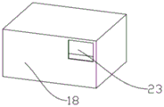
The air-conditioning indoor unit 1 comprises an outer cover 17, and a fresh air device 7 is installed in the outer cover 17. In this embodiment, the housing 17 includes a housing 18 and a baffle 21, an opening 20 is disposed at one end of the housing 18, the baffle 21 is matched with the opening 20 of the housing 18, and the baffle 21 and the housing 18 are matched to form an accommodating space for accommodating the fresh air device 7. The bottom of the housing 18 is provided with a through hole 22, and the front side of the housing is provided with a through hole 23; the through hole 22 corresponds to the fresh air pipe joint 10 at the top of the indoor unit 1 of the air conditioner; a fresh air pipe joint 16 on the fresh air device 7 penetrates through the through hole 22 and the fresh air pipe joint 10; the through hole 23 corresponds to the fresh air outlet 15 on the fan module 11. The fresh air device 7 is installed in the housing 18 through an opening 20 on the housing 18, and then a baffle 21 is installed to shield. In this embodiment, the opening 20 of the housing 18 is disposed at the rear side; the appearance of the air-conditioning indoor unit 1 is beautiful. In addition, in the embodiment, the fresh air device 7 is installed in the outer cover 17, so that the fresh air device 7 and the outer cover 17 are integrated, and the top of the indoor unit 1 of the air conditioner is convenient to disassemble and assemble.
The utility model arranges the fresh air device 7 at the top of the indoor unit 1 of the air conditioner, does not occupy the inner space of the indoor unit 1 of the air conditioner, and reduces the influence on the size of the indoor unit of the air conditioner; in addition, the fresh air outlet 15 of the fresh air device 7 is arranged on the front side, and fresh air is blown to the front side of the indoor unit 1 of the air conditioner, so that the indoor diffusion of the fresh air is facilitated. The bottom of the fresh air device 7 is provided with a fresh air pipe joint 16 which can be connected with a fresh air pipe joint 10 arranged at the top of the indoor unit 1 of the air conditioner, and the fresh air pipe is arranged inside the indoor unit 1 of the air conditioner and is connected with the fresh air device 7 through the fresh air pipe joint 10.
The above description is only a preferred embodiment of the present invention, and is not intended to limit the present invention in other forms, and any person skilled in the art may use the above-mentioned technical contents to change or modify the equivalent embodiment into equivalent changes and apply to other fields, but any simple modification, equivalent change and modification made to the above embodiments according to the technical matters of the present invention will still fall within the protection scope of the technical solution of the present invention.
Claims (10)
1. The air-conditioning indoor unit comprises an electric control box (3), a heat exchanger (2), a base (24) and a shell combined with the base (24); the heat exchanger (2) is arranged in the shell, and the heat exchanger (2) comprises a connecting end (6) connected with an outdoor unit; the shell and the base (24) jointly define a mounting cavity for accommodating the electric control box (3), and the electric control box (3) is positioned on one side of the connecting end (6) of the heat exchanger (2); the method is characterized in that: the air-conditioning indoor unit (1) comprises a fresh air device (7), wherein the fresh air device (7) is arranged outside the air-conditioning indoor unit (1) and is positioned at the top of the electric control box (3); the fresh air device (7) comprises a fresh air outlet (15) facing the front side of the indoor unit (1) of the air conditioner.
2. An indoor unit of an air conditioner according to claim 1, wherein: the fresh air device (7) comprises a fan module (11) and an air inlet cavity (12); the air inlet cavity (12) is arranged at the top of the indoor unit (1) of the air conditioner; the fan module (11) is positioned at the top of the air inlet cavity (12) and is communicated with the air inlet cavity (12).
3. An indoor unit of an air conditioner according to claim 2, wherein: the top of the air inlet cavity (12) is provided with a fresh air communicating opening (13); the fan module (11) comprises a fresh air suction inlet (14); the fresh air suction inlet (14) is connected with the fresh air communication port (13).
4. An indoor unit of an air conditioner according to claim 1, wherein: the air-conditioning indoor unit (1) comprises a side end plate (8) located on one side of a connecting end (6) of the heat exchanger (2), a gap is formed between the side end plate (8) and the electric control box (3), and an accommodating groove (9) is formed between the side end plate (8) and the end of the base (24).
5. An indoor unit of an air conditioner according to claim 4, wherein: fresh air device (7) bottom is equipped with fresh air pipe joint (16), fresh air pipe joint (16) can connect the fresh air pipe.
6. An indoor unit of an air conditioner according to claim 5, wherein: a fresh air pipe interface (10) is arranged in the area, corresponding to the accommodating groove (9), of the top of the indoor unit (1) of the air conditioner; the fresh air pipe joint (16) corresponds to the fresh air pipe joint (10) at the top of the indoor unit (1) of the air conditioner and penetrates through the fresh air pipe joint (10) to enter the accommodating groove (9).
7. An indoor unit of an air conditioner according to claim 5, wherein: the fresh air device (7) is covered with an outer cover (17).
8. An indoor unit of an air conditioner according to claim 7, wherein: a through hole (22) is formed in the bottom of the outer cover (17), and the through hole (22) corresponds to the fresh air pipe joint (16); the fresh air pipe joint (16) on the fresh air device (7) penetrates through the through hole (22).
9. An indoor unit of an air conditioner according to claim 8, wherein: the housing (17) comprises a casing (18); an opening (20) is formed in one end of the housing (18), and a baffle plate (21) is arranged outside the opening (20); the baffle (21) and the housing (18) are matched to form an accommodating space for accommodating the fresh air device (7).
10. An indoor unit of an air conditioner according to claim 1, wherein: an air inlet (4) is formed in the top of the air-conditioning indoor unit (1), and the fresh air device (7) is located adjacent to the air inlet (4).
Priority Applications (1)
| Application Number | Priority Date | Filing Date | Title |
|---|---|---|---|
| CN201921519843.7U CN210511916U (en) | 2019-09-11 | 2019-09-11 | Indoor unit of air conditioner |
Applications Claiming Priority (1)
| Application Number | Priority Date | Filing Date | Title |
|---|---|---|---|
| CN201921519843.7U CN210511916U (en) | 2019-09-11 | 2019-09-11 | Indoor unit of air conditioner |
Publications (1)
| Publication Number | Publication Date |
|---|---|
| CN210511916U true CN210511916U (en) | 2020-05-12 |
Family
ID=70569759
Family Applications (1)
| Application Number | Title | Priority Date | Filing Date |
|---|---|---|---|
| CN201921519843.7U Active CN210511916U (en) | 2019-09-11 | 2019-09-11 | Indoor unit of air conditioner |
Country Status (1)
| Country | Link |
|---|---|
| CN (1) | CN210511916U (en) |
Cited By (1)
| Publication number | Priority date | Publication date | Assignee | Title |
|---|---|---|---|---|
| CN114110754A (en) * | 2021-11-26 | 2022-03-01 | Tcl空调器(中山)有限公司 | Indoor unit of air conditioner |
-
2019
- 2019-09-11 CN CN201921519843.7U patent/CN210511916U/en active Active
Cited By (1)
| Publication number | Priority date | Publication date | Assignee | Title |
|---|---|---|---|---|
| CN114110754A (en) * | 2021-11-26 | 2022-03-01 | Tcl空调器(中山)有限公司 | Indoor unit of air conditioner |
Similar Documents
| Publication | Publication Date | Title |
|---|---|---|
| CN210463245U (en) | Indoor unit of air conditioner | |
| MY136575A (en) | Air conditioner | |
| CN107490073B (en) | Air conditioner indoor unit and air conditioner | |
| CN106196286B (en) | Cabinet air-conditioner and mixed wind method | |
| CN210511916U (en) | Indoor unit of air conditioner | |
| CN210832261U (en) | Floor type air conditioner indoor unit and air conditioner | |
| CN108278674B (en) | Wall-mounted air conditioner indoor unit and wall-mounted air conditioner | |
| CN216592216U (en) | Fresh air device and air conditioner indoor unit with same | |
| CN210463243U (en) | Indoor unit of air conditioner | |
| CN1410727A (en) | Intelligent residence energy saving air conditioning system and its air regulating method | |
| CN210463244U (en) | Indoor unit of air conditioner | |
| CN201314647Y (en) | Indoor unit of triangular vertical air-conditioner | |
| CN208011869U (en) | Wall-hanging air conditioner indoor unit and wall-hanging air conditioner | |
| JPH02169938A (en) | Air conditioner | |
| CN218645743U (en) | Mounting structure and air conditioner of new tuber pipe | |
| CN206989403U (en) | A kind of VMC | |
| CN221197555U (en) | Window air conditioner | |
| CN220689214U (en) | Wall-mounted environment all-in-one machine | |
| CN217817061U (en) | Machine and air conditioner in new trend air conditioning | |
| CN217357176U (en) | Wall-mounted air conditioner indoor unit and air conditioner | |
| CN214949640U (en) | Air purifier for desktop mini office | |
| CN213019944U (en) | Machine in new trend system and air conditioning | |
| CN219955572U (en) | Fresh air module and air conditioner | |
| WO2003029726A1 (en) | Outdoor unit of air conditioner and partition plate of air conditioner | |
| CN211695284U (en) | Automatic air supplement device with oil smoke heat recovery function |
Legal Events
| Date | Code | Title | Description |
|---|---|---|---|
| GR01 | Patent grant | ||
| GR01 | Patent grant | ||
| CP03 | Change of name, title or address |
Address after: No.1 Haixin Road, Nancun Town, Pingdu City, Qingdao City, Shandong Province Patentee after: Hisense Air Conditioning Co.,Ltd. Country or region after: China Address before: No. 151, Zhuzhou Road, Laoshan District, Qingdao, Shandong Patentee before: HISENSE (SHANDONG) AIR-CONDITIONING Co.,Ltd. Country or region before: China |
|
| CP03 | Change of name, title or address |