CN210453251U - Mixer - Google Patents
Mixer Download PDFInfo
- Publication number
- CN210453251U CN210453251U CN201920579270.0U CN201920579270U CN210453251U CN 210453251 U CN210453251 U CN 210453251U CN 201920579270 U CN201920579270 U CN 201920579270U CN 210453251 U CN210453251 U CN 210453251U
- Authority
- CN
- China
- Prior art keywords
- water
- accommodating space
- flushing
- pipe
- concrete
- Prior art date
- Legal status (The legal status is an assumption and is not a legal conclusion. Google has not performed a legal analysis and makes no representation as to the accuracy of the status listed.)
- Expired - Fee Related
Links
Images


Abstract
A blender, comprising: the body is internally provided with an accommodating space; the water inlet pipe is arranged at the top of the accommodating space; the flushing pipe is arranged on the periphery of the top of the accommodating space and on the side wall of the accommodating space, is communicated with the water inlet pipe, and is provided with a water outlet facing the side wall of the accommodating space. This embodiment is in the use, when needs are to the concrete mixing, when adding water, add the water yield through external control valve control, compare with traditional intaking through the inlet tube, this mixer not only intakes through the inlet tube, the water of inlet tube the inside can flow to the flushing pipe in, water in the flushing pipe is towards the accommodation space lateral wall through the delivery port, the water that passes through the accommodation space lateral wall through the delivery port can wash the accommodation space lateral wall, wash away the material such as concrete of accumulation last time, the problem that the long-time upgrade of concrete is thicker has been avoided.
Description
Technical Field
The utility model relates to a stirring apparatus, especially, relate to a stirrer.
Background
A stirrer is a construction engineering machine and is mainly used for stirring building materials such as cement, sand and stone, various dry-mixed mortar and the like. This is a machine in which a shaft with blades rotates in a cylinder or tank to mix and stir a plurality of materials into a mixture or a suitable consistency. The mixer is divided into various types, such as a forced mixer, a single horizontal shaft mixer, a double shaft humidifying mixer and the like.
The existing double-shaft humidifying stirrer consists of a stirring bin and two stirring shafts, wherein the stirring shafts are provided with stirring blades, materials to be stirred such as concrete and the like are stirred through the stirring blades, water pipes for adding water are arranged above the stirrer, water is added when the stirrer needs to add water, however, in the stirring process, the stirrer stirs the stirring materials in the stirring bin due to the stirring blades, the stirring blades can drive the concrete to be scattered on the bin wall, the running time is longer and longer, the concrete on the surface of the bin wall is thicker and thicker, under the general condition, the sealed bin is opened for cleaning after running for one week, and the working strength of workers can be increased due to the fact that the bin is generally sealed.
SUMMERY OF THE UTILITY MODEL
An object of the utility model is to overcome one of the above-mentioned technical problem that exists among the prior art, provide a reduce mixer of machine storehouse surface concrete accumulation.
In order to realize the technical purpose, the technical effect is achieved, the utility model discloses a realize through following technical scheme:
a blender, comprising:
the body is internally provided with an accommodating space;
the water inlet pipe is arranged at the top of the accommodating space;
the flushing pipe is arranged on the periphery of the top of the accommodating space and on the side wall of the accommodating space, is communicated with the water inlet pipe, and is provided with a water outlet facing the side wall of the accommodating space.
The mixer of the utility model, wherein, include:
the first flushing head is communicated with the water outlet of the flushing pipe, and the water outlet end of the first flushing head faces the side wall of the accommodating space.
The mixer of the utility model, wherein, include:
and the pressure valve is connected with the flushing pipe and the water inlet pipe and used for maintaining the pressure in the flushing pipe.
The mixer of the utility model, wherein, include:
the stirring shaft is used for driving the stirring blades of the stirrer;
the second flushing head is arranged at the lower end of the water inlet pipe, is positioned in a vertical plane together with the stirring shaft, is flat and has the length direction consistent with that of the stirring shaft.
The mixer of the utility model, wherein, include:
the discharge port is arranged at the bottom of the accommodating space and is arranged between the two stirring shafts;
the front end and the rear end of the discharge door are rotationally connected with the accommodating space through a rotating shaft;
the baffle sets up in the discharge gate lower extreme left and right sides, with discharge gate left and right sides fixed connection.
The stirring machine of the utility model, wherein, the baffle is vertical setting.
Compared with the prior art, the beneficial effects of the utility model are that:
this embodiment is in the use, when needs are to the concrete mixing, when adding water, add the water yield through external control valve control, compare with traditional intaking through the inlet tube, this mixer not only intakes through the inlet tube, the water of inlet tube the inside can flow to the flushing pipe in, water in the flushing pipe is towards the accommodation space lateral wall through the delivery port, the water that passes through the accommodation space lateral wall through the delivery port can wash the accommodation space lateral wall, wash away the material such as concrete of accumulation last time, the problem that the long-time upgrade of concrete is thicker has been avoided.
Drawings
FIG. 1 is a view of the overall structure of the present invention;
FIG. 2 is a view of the structure of the present invention including a rinsing head;
FIG. 3 is a cross-sectional view taken along line A-A of FIG. 1;
FIG. 4 is a cross-sectional view taken along line B-B of FIG. 1;
FIG. 5 is a side view of the water inlet pipe of the present invention;
Detailed Description
Referring to fig. 1-5, it should be understood by those skilled in the art that the terms "one end", "the other end", "vertical", etc. in the disclosure of the present invention are based on the orientation or positional relationship shown in the drawings, which are only for convenience of description and simplicity of description, and do not indicate or imply that the device or element so referred to must have a particular orientation, be constructed and operated in a particular orientation, and thus the above terms should not be construed as limiting the present invention.
The existing double-shaft humidifying stirrer consists of a stirring bin and two stirring shafts, wherein the stirring shafts are provided with stirring blades, materials to be stirred such as concrete and the like are stirred by the stirring blades, a water pipe for adding water is arranged above the stirrer, water is added when the stirrer needs to add water, however, in the stirring process, the stirring blades can drive the concrete to be scattered on a bin wall as the stirring blades stir the materials in the stirring bin, the running time is longer and longer, the concrete on the surface of the bin wall is thicker and thicker to a certain degree, the friction between the stirring blades and the concrete is larger and larger, the bin can be cleaned when the friction is larger to a certain degree, generally, the sealed bin needs to be opened for cleaning after running for one week, and the working strength of workers can be increased as the bin is generally sealed, based on this, there is provided:
a blender, comprising:
a body 100, in which an accommodating space 110 is arranged;
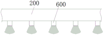
a water inlet pipe 200 disposed at the top of the accommodating space 110;
the flushing pipe 300 is disposed at a position on the sidewall of the accommodating space 110 around the top of the accommodating space 110, is communicated with the water inlet pipe 200, and is provided with a water outlet 310 facing the sidewall of the accommodating space 110.
This embodiment is in the use, when needs are to the concrete mixing, when adding water, add the water yield through external control valve control, compare with traditional water inlet pipe 200 intaking through the inlet tube, this mixer not only intakes through inlet tube 200, the water of inlet tube the inside can flow to the flushing pipe 300 in, water in the flushing pipe 300 dashes to the accommodation space lateral wall through delivery port 310, the water that passes through the accommodation space lateral wall through delivery port 310 can wash the accommodation space lateral wall, wash away the material such as the concrete of accumulation last time, the long-time problem of thickening more offstage of concrete has been avoided.
It should be noted that, the mixer is generally operated continuously, so that after one time of mixing, the mixed concrete is poured out, and then the next time of mixing is carried out, so that two times of mixing are generally not separated by a long time, and the concrete is not solidified in the time, so that the concrete can be flushed from the side wall, and in addition, in the completion of one service cycle, if the concrete is mixed, the mixer and the side wall can be flushed by directly discharging water under the condition that the mixer is not used for a long time next; it should be noted that the water outlet 310 is spaced from the accommodating space 110 by a certain distance to ensure that water can flow out of the water outlet 310, the number of the water outlets is not limited, the water outlet 310 is provided at a position opposite to the side wall of the accommodating space, the water inlet pipe is supplied with water from an external water source, and water with a certain pressure can be provided by a booster pump or tap water.
The mixer provided by the exemplary embodiment includes a first flushing head 400, which is communicated with the water outlet 310 of the flushing pipe 300, and the water outlet end of the first flushing head 400 faces the side wall of the accommodating space 110, the first flushing head 400 plays a role in guiding out water flow, and can more accurately guide water to the position of the side wall of the accommodating space, the first flushing head 400 may be a short pipe, a water flow channel is arranged in the middle of the short pipe, one end of the short pipe is communicated with the water outlet 310, the short pipe is fixedly connected with the flushing pipe 300, and specifically can be welded or connected by glue or a clamp, which is a common means, and not described in detail herein, the other end of the short pipe faces the side wall of the accommodating space for spraying water onto the side wall of the accommodating space, and the other end of the short pipe can also be sprayed by a spraying manner, so that the sprayed water is more uniform, that is, the other end of the short pipe is sealed, the water area sprayed by the small holes is large, and the spraying is uniform.
For example, when the flushing pipe 300 is directly communicated with the water inlet pipe 200, water entering the flushing pipe 300 from the water inlet pipe 200 may cause a reduction in water pressure, and further cause water in the flushing pipe 300 to be sprayed out of a part of the water outlet 310 or the first flushing head 400, a pressure valve 320 is disposed at a connection between the flushing pipe 300 and the water inlet pipe 300, the pressure valve 320 is communicated with the flushing pipe 300 and the water inlet pipe 200 to ensure a stable pressure in the flushing pipe 300, the pressure valve 320 may be a balance valve for balancing the pressure between the flushing pipe 300 and the water inlet pipe 200 to ensure a stable pressure in the flushing pipe 300, and when the pressure in the water inlet pipe 200 is too high, water may enter the flushing valve through the balance valve; when the pressure of the inlet pipe is too small, water can still enter the flushing pipe 300, and only the flushing pipe 300 has small water flow.
The blender provided by the embodiment comprises a blender body,
the stirring shaft 500 is used for driving stirring blades of the stirrer;
and the second flushing head 600 is arranged at the lower end of the water inlet pipe 200, is positioned in a vertical plane together with the stirring shaft 500, is flat, and has the length direction consistent with that of the stirring shaft 500.
At present, the second flushing head 600 of the water inlet is generally in a circular design, and when water enters through the second flushing head 600, the stirring shaft 500 of the stirring machine is flushed, but the circular design limits the flushing range of the stirring shaft, the second flushing head 600 is designed to be flat, when the water comes out from the second flushing head 600, the stirring shaft 500 is in a fan shape or a rectangular shape, the range of flushing the stirring shaft 500 is enlarged, the stirring shaft 500 can be flushed more completely, it needs to be noted that the number of the second flushing heads 600 is not limited, it needs to be noted that the stirring shaft 500 is powered by a motor or other rotating mechanisms to drive the stirring shaft, which is not shown in the figure, the motor can be directly connected with the stirring shaft, or can be driven by a gear, which is the prior art and will not be described in detail herein.
The mixer that this embodiment provided includes:
a discharge port 700 disposed at the bottom of the accommodating space 110 and between the two stirring shafts 500;
the discharge door 800 is rotatably connected with the accommodating space 110 through a rotating shaft at the front end and the rear end;
and the baffle 900 is arranged at the left side and the right side of the lower end of the discharge hole 700.
It should be noted that, as shown in the figure, the outlet of the present dual-shaft mixer is located between two mixing shafts, and the front and back ends of the discharge door 800 are rotatably connected to the outlet through a rotating shaft, and can be connected through a bearing when being specifically connected, and can be rotatably opened or closed by being driven by an external motor, at present, in this way, because of matching with the mixing shafts during discharging, the mixer housing at the bottom of each mixing shaft is of an arc design, and in this design, when concrete is discharged from the discharge port 700, the concrete will slowly stick to the concrete on the housing at the bottom of the mixing shaft due to splashing of the concrete during discharging, and as a result, the concrete will be accumulated more and more in the past, and finally the discharge door 800 will be blocked; therefore, the baffle plates 900 are arranged on the two sides of the discharge door 800, the baffle plates 900 are arranged on the left side and the right side of the discharge port 700, the baffle plates are made of steel or other hard materials and are fixedly connected with the left side and the right side of the discharge port by welding or screw bolt clamps, after concrete materials come out from the discharge port 700 due to the existence of the baffle plates, the concrete materials cannot splash onto a shell at the bottom of the stirring shaft and directly flow down from the baffle plates and cannot be adhered when flowing down from the baffle plates, and it needs to be noted that the baffle plates 900 are preferably vertically arranged, so that concrete cannot be adhered, and it needs to be noted that concrete can flow down from the baffle plates every time, and concrete which flows down at every time can be carried under the concrete belt which does not flow down last time, so that concrete cannot be adhered.
The above-mentioned embodiments are only to describe the preferred embodiments of the present invention, but not to limit the scope of the present invention, and various modifications and improvements made by those skilled in the art without departing from the design spirit of the present invention should fall into the protection scope defined by the claims of the present invention.
Claims (6)
1. A blender, comprising:
the device comprises a machine body (100), wherein an accommodating space (110) is arranged in the machine body;
the water inlet pipe (200) is arranged at the top of the accommodating space (110);
the flushing pipe (300) is arranged at the position of the side wall of the accommodating space (110) at the periphery of the top of the accommodating space (110), is communicated with the water inlet pipe (200), and is provided with a water outlet (310) facing the side wall of the accommodating space (110).
2. A mixer according to claim 1, comprising:
the first flushing head (400) is communicated with the water outlet (310) of the flushing pipe (300), and the water outlet end of the first flushing head (400) faces the side wall of the accommodating space (110).
3. A mixer according to claim 1, comprising:
and the pressure valve (320) is connected with the flushing pipe (300) and the water inlet pipe (200) and is used for maintaining the pressure in the flushing pipe (300).
4. A mixer according to claim 1, comprising:
the stirring shaft (500) is used for driving stirring blades of the stirrer;
the second flushing head (600) is arranged at the lower end of the water inlet pipe (200), is positioned in a vertical plane with the stirring shaft (500), is flat, and has the length direction consistent with that of the stirring shaft (500).
5. A mixer according to claim 1, comprising:
the discharge port (700) is arranged at the bottom of the accommodating space (110) and is arranged between the two stirring shafts;
the front end and the rear end of the discharge door (800) are rotationally connected with the accommodating space (110) through a rotating shaft;
and the baffle plates (900) are arranged at the left side and the right side of the lower end of the discharge hole (700) and are fixedly connected with the left side and the right side of the discharge hole (700).
6. A mixer according to claim 5, wherein the baffle (900) is vertically disposed.
Priority Applications (1)
| Application Number | Priority Date | Filing Date | Title |
|---|---|---|---|
| CN201920579270.0U CN210453251U (en) | 2019-04-26 | 2019-04-26 | Mixer |
Applications Claiming Priority (1)
| Application Number | Priority Date | Filing Date | Title |
|---|---|---|---|
| CN201920579270.0U CN210453251U (en) | 2019-04-26 | 2019-04-26 | Mixer |
Publications (1)
| Publication Number | Publication Date |
|---|---|
| CN210453251U true CN210453251U (en) | 2020-05-05 |
Family
ID=70430034
Family Applications (1)
| Application Number | Title | Priority Date | Filing Date |
|---|---|---|---|
| CN201920579270.0U Expired - Fee Related CN210453251U (en) | 2019-04-26 | 2019-04-26 | Mixer |
Country Status (1)
| Country | Link |
|---|---|
| CN (1) | CN210453251U (en) |
-
2019
- 2019-04-26 CN CN201920579270.0U patent/CN210453251U/en not_active Expired - Fee Related
Similar Documents
| Publication | Publication Date | Title |
|---|---|---|
| CN110815550A (en) | Construct dedicated horizontal high-efficient agitating unit of earth that mixes | |
| CN212528221U (en) | Assembled building chemical material mixing apparatus | |
| CN110450281A (en) | A kind of agitating device for building and its working method | |
| CN210453251U (en) | Mixer | |
| CN210820201U (en) | Green building mortar agitating unit | |
| CN209775127U (en) | concrete mixer | |
| CN210361906U (en) | Dosing unit is used in concrete processing | |
| CN209920217U (en) | Concrete mixer | |
| CN218189352U (en) | Raw material blending device for processing bone china tableware | |
| CN211415735U (en) | Concrete mortar mixing equipment | |
| CN213703994U (en) | Concrete processing equipment convenient to maintain | |
| CN213078244U (en) | Coating mixing apparatus for building | |
| CN208213052U (en) | A kind of architectural engineering Efficient Agitator | |
| CN210875051U (en) | Anti-blocking overflow water recovery device for stirrer | |
| CN208018549U (en) | A kind of civil engineering movable high-efficiency blender | |
| CN209163380U (en) | Mortar spraying device | |
| CN207056477U (en) | A kind of industrial chemicals agitating device | |
| CN211842553U (en) | Building engineering construction agitating unit | |
| CN212636121U (en) | Device for reducing material sticking of mixer shell | |
| CN215282600U (en) | Convenient abluent agitating unit for cement processing | |
| CN218398845U (en) | Discharging device of stirrer | |
| CN204505546U (en) | A kind of cement stirring device | |
| CN218077467U (en) | High-efficient machine that mixes of chinese-medicinal material | |
| CN220864364U (en) | Combined mortar stirring device for building construction | |
| CN214353297U (en) | Mixer for ready-mixed concrete |
Legal Events
| Date | Code | Title | Description |
|---|---|---|---|
| GR01 | Patent grant | ||
| GR01 | Patent grant | ||
| CF01 | Termination of patent right due to non-payment of annual fee |
Granted publication date: 20200505 |
|
| CF01 | Termination of patent right due to non-payment of annual fee |