CN210371663U - Ball guide rail for vehicle armrest platform - Google Patents
Ball guide rail for vehicle armrest platform Download PDFInfo
- Publication number
- CN210371663U CN210371663U CN201921175477.8U CN201921175477U CN210371663U CN 210371663 U CN210371663 U CN 210371663U CN 201921175477 U CN201921175477 U CN 201921175477U CN 210371663 U CN210371663 U CN 210371663U
- Authority
- CN
- China
- Prior art keywords
- ball
- guide rail
- groove
- vehicle armrest
- frame
- Prior art date
- Legal status (The legal status is an assumption and is not a legal conclusion. Google has not performed a legal analysis and makes no representation as to the accuracy of the status listed.)
- Active
Links
- 239000010687 lubricating oil Substances 0.000 claims description 7
- 230000000149 penetrating effect Effects 0.000 claims description 2
- 238000005452 bending Methods 0.000 abstract 1
- 238000005096 rolling process Methods 0.000 description 4
- 238000005253 cladding Methods 0.000 description 3
- 230000000694 effects Effects 0.000 description 3
- 230000003139 buffering effect Effects 0.000 description 2
- 230000007547 defect Effects 0.000 description 1
- 238000010586 diagram Methods 0.000 description 1
- 238000010030 laminating Methods 0.000 description 1
- 239000000463 material Substances 0.000 description 1
- 230000004048 modification Effects 0.000 description 1
- 238000012986 modification Methods 0.000 description 1
Images


Landscapes
- Bearings For Parts Moving Linearly (AREA)
Abstract
The utility model discloses a ball guide for vehicle armrest platform, including outer guide rail, the inner guide rail, ball frame and ball, the inside wall of outer guide rail is provided with interior spout, the lateral wall of inner guide rail is provided with outer spout, the both sides interval arrangement of ball frame has a plurality of mounting panels of upwards bending, be equipped with the rectangle ball groove that runs through to the bottom on the mounting panel, the both sides edge in rectangle ball groove is equipped with the ball portion of bearing towards the inboard integrated into one piece of ball frame respectively, the ball is installed between the ball portion, the area of contact at reducible ball and rectangle ball groove edge, the frictional force that makes the ball receive reduces, and be equipped with the cambered surface portion between ball portion and rectangle ball groove, effectively reduce the frictional force between ball and the ball portion, it is more smooth and easy to make the guide rail roll.
Description
Technical Field
The utility model relates to a guide rail, especially a ball guide.
Background
The existing ball guide rail of the vehicle armrest platform comprises an outer guide rail, an inner guide rail and a ball frame, wherein a ball groove capable of containing balls is formed in the ball frame, the ball groove is circular, the diameter of the ball groove is slightly larger than that of the balls, the balls can be just contained in the ball groove, and when the balls roll in the ball groove, the balls can rub with the edge of the ball groove, so that the rolling is not smooth.
Disclosure of Invention
In order to overcome the defects of the prior art, the utility model provides a keep the rolling smooth and easy ball guide who is used for vehicle armrest platform of ball guide.
The utility model provides a technical scheme that its technical problem adopted is:
the utility model provides a ball guide for vehicle armrest platform, includes outer guide rail, inner guide rail, ball frame and ball, the inside wall of outer guide rail is provided with interior spout, the lateral wall of inner guide rail is provided with outer spout, the both sides interval arrangement of ball frame has a plurality of mounting panels that upwards bend, be provided with the rectangle ball groove that runs through to the bottom on the mounting panel, the both sides face in rectangle ball groove is provided with the orientation respectively the inboard integrated into one piece's of ball frame holds the ball portion, the shape of holding the ball portion with the shape of ball agrees with mutually, hold the ball portion with be provided with cambered surface portion between the rectangle ball groove edge, the top in rectangle ball groove is provided with arc portion, the radius of arc portion is greater than the radius of ball makes the ball with form the triangle clearance that can store lubricating oil between the arc portion.
The shape of outer guide rail lateral wall is the arc, the protection shield is installed at the top of interior guide rail, the both sides edge of protection shield be equipped with the portion of borduring that outer guide rail lateral wall agrees with mutually, after the assembly, the portion cladding of borduring is in the outside of outer guide rail, and not mutual contact.
The top of the ball frame is provided with a limiting block, and the bottom of the inner guide rail is provided with a thrust block corresponding to the position of the limiting block.
Limiting plates bent upwards are arranged at two ends of the outer guide rail.
The radian range of the inner sliding groove and the outer sliding groove is 0.8-1 rad.
The utility model has the advantages that: the utility model discloses be equipped with the rectangle pearl groove that runs through to the bottom on the mounting panel, the both sides edge in rectangle pearl groove is equipped with the ball portion of the inboard integrated into one piece of orientation ball frame respectively, and the ball is installed between ball portion, and the area of contact at reducible ball and rectangle pearl groove edge makes the frictional force that the ball receives reduce, and is equipped with cambered surface portion between ball portion and rectangle pearl groove, effectively reduces the frictional force between ball and the ball portion, makes the guide rail roll more smoothly.
Drawings
The present invention will be further explained with reference to the drawings and examples.
Fig. 1 is a schematic structural diagram of the present invention;
fig. 2 is an exploded schematic view of the present invention;
fig. 3 is a schematic cross-sectional view of the present invention;
FIG. 4 is a schematic structural view of a mounting plate;
FIG. 5 is a front view of the mounting plate;
fig. 6 is a schematic structural view of the inner rail.
Detailed Description
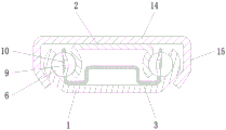
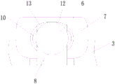
Referring to fig. 1 to 6, a ball guide rail for a vehicle armrest platform includes an outer guide rail 1, an inner guide rail 2, a ball frame 3, and balls 6, an inner sliding groove 4 is formed in an inner side wall of the outer guide rail 1, an outer sliding groove 5 is formed in an outer side wall of the inner guide rail 2, a plurality of upwardly bent mounting plates 7 are arranged at intervals on both sides of the ball frame 3, a rectangular ball groove 8 penetrating to a bottom is formed in the mounting plates 7, ball receiving portions 9 integrally formed toward an inner side of the ball frame 3 are respectively formed on both side surfaces of the rectangular ball groove 8, a shape of the ball receiving portion 9 is matched with a shape of the balls 6, the balls 6 are mounted between the ball receiving portions 9, the rectangular ball groove 8 opens a bottom of the mounting plate 7, a contact area between the balls 6 and edges of the rectangular ball groove 8 is reduced, and friction force applied to the balls 6 is reduced, simultaneously because of the piece that the friction produced also can be followed the bottom opening of rectangle ball groove 8 drops, prevents that the piece from piling up rectangle ball groove 8 with between the ball 6, the influence rolls, ball portion 9 with be provided with cambered surface portion 10 between the rectangle ball groove 8 edge, reduce ball 6 with frictional force between the ball portion 9 makes the roll more smooth and easy, the assembly back, ball frame 3 installs in outer guide rail 1, inner guide rail 2 installs in ball frame 3, ball 6 with interior spout 4 and the laminating of outer spout 5.
The top in rectangle ball groove 8 is provided with arc portion 12, the radius of arc portion 12 is greater than the radius of ball 6, makes ball 6 with form the triangle clearance 13 that can store lubricating oil between arc portion 12, further reduce ball 6 with the area of contact at rectangle ball groove 8 edge, in addition, triangle clearance 13 has more the effect of storing lubricating oil, and when lubricating oil was not enough, ball 6 can take away when rolling the partial lubricating oil in triangle clearance 13, in order to keep have appropriate amount lubricating oil on the ball 6.
The shape of 1 lateral wall of outer guide rail is the arc, protection shield 14 is installed at the top of interior guide rail 2, the both sides edge of protection shield 14 be equipped with 1 lateral wall of outer guide rail agrees with portion 15 of borduring mutually, the assembly back, 15 cladding in portion of borduring is in the outside of outer guide rail 1, and each other contactless, protection shield 14 can play certain guard action to ball guide inside, simultaneously portion of borduring 15 cladding is in the outside of outer guide rail 1 plays and prevents the effect that interior guide rail 2 derailed.
The top of ball frame 3 is provided with stopper 18, the bottom of interior guide rail 2 corresponds the position of stopper 18 is provided with thrust block 16, interior guide rail 2 can promote when sliding to the certain distance ball frame 3 slides simultaneously, can be based on the gliding actual length of guide rail to be right the length of ball frame 3 is injectd to reduce material cost.
The utility model discloses a buffer structure of outer guide rail, including outer guide rail 1, limiting plate 17 can prevent inner guide rail 2 breaks away from outer guide rail 1, the buffering piece can inner guide rail 2 with play buffering, the effect of silence when limiting plate 17 collides.
The radian ranges of the inner chute 4 and the outer chute 5 are 0.8-1rad, so that the contact area of the ball 6 with the inner chute 4 and the outer chute 5 is reduced, and the rolling is smoother.
The above embodiments do not limit the scope of the present invention, and those skilled in the art can make equivalent modifications and variations without departing from the overall concept of the present invention.
Claims (5)
1. A ball guide rail for a vehicle armrest platform comprises an outer guide rail (1), an inner guide rail (2), a ball frame (3) and balls (6), wherein an inner chute (4) is formed in the inner side wall of the outer guide rail (1), an outer chute (5) is formed in the outer side wall of the inner guide rail (2), the ball guide rail is characterized in that a plurality of mounting plates (7) which are bent upwards are arranged on the two sides of the ball frame (3) at intervals, a rectangular ball groove (8) penetrating to the bottom is formed in each mounting plate (7), two side faces of each rectangular ball groove (8) are respectively provided with a ball bearing part (9) which faces the inner side of the ball frame (3) and is integrally formed, the shape of each ball bearing part (9) is matched with the shape of each ball (6), an arc surface part (10) is arranged between each ball bearing part (9) and the edge of each rectangular ball groove (8), and an arc part (12) is arranged at the top of each rectangular ball groove, the radius of the arc-shaped part (12) is larger than that of the ball (6), so that a triangular gap (13) capable of storing lubricating oil is formed between the ball (6) and the arc-shaped part (12).
2. The ball guide rail for the vehicle armrest platform according to claim 1, wherein the outer side wall of the outer guide rail (1) is arc-shaped, the top of the inner guide rail (2) is provided with a protection plate (14), two side edges of the protection plate (14) are provided with edge wrapping portions (15) which are matched with the outer side wall of the outer guide rail (1), and after assembly, the edge wrapping portions (15) wrap the outer side of the outer guide rail (1) and are not in contact with each other.
3. The ball guide rail for a vehicle armrest platform according to claim 1, characterized in that a stopper (18) is provided at the top of the ball frame (3), and a thrust block (16) is provided at the bottom of the inner guide rail (2) at a position corresponding to the stopper (18).
4. The ball guide rail for a vehicle armrest platform according to claim 1, characterized in that both ends of the outer guide rail (1) are provided with upwardly bent stopper plates (17).
5. The ball guide rail for a vehicle armrest platform according to claim 1, characterized in that the radian range of the inner chute (4) and the outer chute (5) is 0.8-1 rad.
Priority Applications (1)
| Application Number | Priority Date | Filing Date | Title |
|---|---|---|---|
| CN201921175477.8U CN210371663U (en) | 2019-07-23 | 2019-07-23 | Ball guide rail for vehicle armrest platform |
Applications Claiming Priority (1)
| Application Number | Priority Date | Filing Date | Title |
|---|---|---|---|
| CN201921175477.8U CN210371663U (en) | 2019-07-23 | 2019-07-23 | Ball guide rail for vehicle armrest platform |
Publications (1)
| Publication Number | Publication Date |
|---|---|
| CN210371663U true CN210371663U (en) | 2020-04-21 |
Family
ID=70246278
Family Applications (1)
| Application Number | Title | Priority Date | Filing Date |
|---|---|---|---|
| CN201921175477.8U Active CN210371663U (en) | 2019-07-23 | 2019-07-23 | Ball guide rail for vehicle armrest platform |
Country Status (1)
| Country | Link |
|---|---|
| CN (1) | CN210371663U (en) |
-
2019
- 2019-07-23 CN CN201921175477.8U patent/CN210371663U/en active Active
Similar Documents
| Publication | Publication Date | Title |
|---|---|---|
| CN101707903A (en) | Vehicle seat slide device | |
| US7690740B2 (en) | Pull-out guide system for drawers | |
| US6488248B1 (en) | Keyboard mechanism tracking system | |
| JPS61174085A (en) | Guide appartus for door of elevator | |
| US4955160A (en) | Guide wall assembly for drawers | |
| JPS593977U (en) | Slide guide device for vehicle sliding doors | |
| CN210371663U (en) | Ball guide rail for vehicle armrest platform | |
| CN204418935U (en) | A kind of sliding push-pull door hidden track way groove lower railway | |
| CN106724190B (en) | Full-extension drawer slide rail | |
| EP1166681A1 (en) | Slide rail | |
| CN220053583U (en) | Automobile seat track dust-proof device | |
| WO2024230713A1 (en) | Dust protection device for automobile seat rails | |
| JPH0139351Y2 (en) | ||
| CN216071793U (en) | There is rail guidance commodity circulation goods shelves shuttle system | |
| CN208202923U (en) | A kind of door of band VU track | |
| CN212066094U (en) | Aluminum alloy multi-section sliding rail with bearing roller | |
| CN223562698U (en) | Bathroom translation door | |
| JP7328085B2 (en) | Platform door device | |
| CN114992238A (en) | Vice instrument board slide rail structure and vehicle | |
| CN210364926U (en) | Buffering protection structure and electronic equipment comprising same | |
| JP2012188261A (en) | Door device for elevator | |
| CN208298285U (en) | Machine core guiding mechanism and financial self-service equipment | |
| JPS6314305Y2 (en) | ||
| CN206043996U (en) | A kind of drawer guideway | |
| CN212938860U (en) | Adjusting assembly for three-section hidden sliding rail |
Legal Events
| Date | Code | Title | Description |
|---|---|---|---|
| GR01 | Patent grant | ||
| GR01 | Patent grant |