CN210358131U - Christmas ball cover CCD screening device - Google Patents
Christmas ball cover CCD screening device Download PDFInfo
- Publication number
- CN210358131U CN210358131U CN201920793416.1U CN201920793416U CN210358131U CN 210358131 U CN210358131 U CN 210358131U CN 201920793416 U CN201920793416 U CN 201920793416U CN 210358131 U CN210358131 U CN 210358131U
- Authority
- CN
- China
- Prior art keywords
- output
- ball
- transparent horizontal
- vibration
- vibrating
- Prior art date
- Legal status (The legal status is an assumption and is not a legal conclusion. Google has not performed a legal analysis and makes no representation as to the accuracy of the status listed.)
- Active
Links
Images


Abstract
The utility model discloses a ball lid CCD sieving mechanism on christmas, which comprises a frame, be equipped with ball lid screening input device and ball lid screening output device in the frame, ball lid screening input device includes that fixed mounting has the workbin that is used for placing the ball lid of waiting to filter in the frame upper end, the bottom of workbin is equipped with the discharge gate, the below of discharge gate is equipped with into the hopper, it is equipped with the vibration dish to go into the output below of hopper, the output of vibration dish is connected with ball lid delivery track, ball lid delivery track's output links up with the top surface outward flange of a transparent horizontal carousel to make the ball lid of output fall on transparent horizontal carousel; transparent horizontal carousel is close to ball lid delivery track's side and is equipped with at least two sets of high-speed camera, ball lid screening output device is including the output conveyer belt that is located transparent horizontal carousel top at least two sets of high-pressure gas shower nozzle and sets up with the high-pressure gas shower nozzle relatively, the utility model provides high work efficiency has reduced artifical intensity of labour.
Description
The technical field is as follows:
the utility model relates to a ball lid CCD sieving mechanism christmas.
Background art:
the Christmas ball is an article which is bound to be used in Christmas in western countries, the Christmas ball comprises a ball body and a ball cover, the ball body and the ball cover are buckled when the Christmas ball is used, the ball cover penetrates through a thread rope through a hole on the ball cover and is hung on a Christmas tree or other articles, and the ball cover is unqualified because burrs are easily generated in the injection molding process; because the production quantity of Christmas balls is huge, the workload of manual screening is huge, and the Christmas balls are usually screened by adopting a mechanical vibrating screen at present, but the accuracy of the screening mode is poor, and defective products still exist in large quantity.
The utility model has the following contents:
an object of the utility model is to provide a ball lid CCD sieving mechanism christmas, this ball lid CCD sieving mechanism christmas reasonable in design is favorable to improving the accuracy of screening.
In order to realize the purpose, the utility model discloses a technical scheme is:
the utility model discloses ball lid CCD sieving mechanism christmas, including the frame, its characterized in that: the ball cover screening input device comprises a material box fixedly mounted on the upper end of the machine frame and used for placing ball covers to be screened, a discharge port is formed in the bottom of the material box, a feeding hopper is arranged below the discharge port, a vibrating disc is arranged below the output end of the feeding hopper, the output end of the vibrating disc is connected with a ball cover conveying rail, and the output end of the ball cover conveying rail is connected with the outer edge of the top surface of a transparent horizontal turntable so that the output ball covers fall on the transparent horizontal turntable; transparent horizontal rotary table is close to ball lid delivery track's side and is equipped with at least two sets of high-speed cameras, ball lid screening output device is including the output conveyer belt that is located the relative setting of at least two sets of high-pressure gas shower nozzle of transparent horizontal rotary table top and with high-pressure gas shower nozzle, the input of output conveyer belt is close to the edge of transparent horizontal rotary table, the output below of output conveyer belt is equipped with flourishing feed cylinder.
Furthermore, a first vibrating device is installed at the bottom of the feeding hopper, a detection switch used for detecting the number of the ball covers in the vibrating disc is arranged above the vibrating disc, and the detection switch is electrically connected with the first vibrating device through a control unit.
Furthermore, the detection switch comprises a detection seat plate which is positioned above the vibration disc and fixedly connected with the rack, a vertically-penetrated groove hole is formed in the detection seat plate, a rotating block is hinged in the groove hole, a detection rod is fixedly penetrated through the middle part of the rotating block, and the lower end of the detection rod extends into the vibration disc and is used for being in contact with a ball cover in the vibration disc; the vertical test probe who is equipped with the detection mouth down and is used for responding to the top of measuring stick directly over the slotted hole, when the lower extreme of measuring stick does not contact with the ball lid in the vibration dish, the measuring stick is in vertical state, test probe detects the measuring stick and starts through the first vibrating device of the control unit drive, realizes the vibration pan feeding.
Furthermore, the lower end of the detection rod is fixedly connected with a rubber block which is beneficial to being in contact with the ball cover in the vibration disc, and the rubber block is cylindrical.
Further, the feeding hopper is of a groove-shaped structure with a U-shaped cross section and is horizontally placed; the first vibrating device is a direct vibrating flat feeder A, the bottom of the direct vibrating flat feeder A is fixedly installed on the rack, and the top of the direct vibrating flat feeder A is fixedly connected with the bottom of the feeding hopper.
Furthermore, the ball cover conveying track comprises a rectangular track body, the bottom of the track body is connected with a second vibrating device, a sliding groove with an inverted T-shaped section is arranged inside the track body, the input end of the sliding groove is connected with the output end of the vibrating disc, and the output end of the sliding groove is connected with the outer edge of the top surface of the transparent horizontal turntable, so that the ball cover in the vibrating disc can be conveyed to the transparent horizontal turntable through the sliding groove; the track body is horizontally arranged, the second vibration device is a direct vibration flat feeder B, the bottom of the direct vibration flat feeder B is fixedly arranged on the rack, and the top of the direct vibration flat feeder B is fixedly connected with the bottom of the track body; the workbin is hourglass hopper-shaped.
Furthermore, the transparent horizontal turntable rotates clockwise, and the high-speed camera and the high-pressure air nozzle are staggered by 90-240 degrees on the circumference.
Furthermore, both sides of the output conveyer belt are provided with guard plates, and the two guard plates are in a conical opening shape at the input end of the output conveyer belt.
Furthermore, the high-pressure air nozzle is horizontally suspended above the transparent horizontal turntable, and the air outlet of the high-pressure air nozzle is opposite to the central line of the output conveying belt.
Furthermore, the surface of the transparent horizontal turntable is provided with two cleaning heads driven by a rotating motor to rotate, each cleaning head comprises a rotor fixedly connected with a motor output shaft and a sponge layer attached to the lower surface of the rotor, the lower surface of the sponge layer is attached to the surface of the transparent horizontal turntable, the cleaning heads and the transparent horizontal turntable are the same in steering direction, an output guide channel is arranged beside the transparent horizontal turntable and is just opposite to the cleaning heads to output a re-detection part, and the output end of the output guide channel is provided with a charging bucket.
Furthermore, the high-speed camera is electrically connected with the controller respectively, and the opening and closing control valve of the high-pressure air nozzle is electrically connected with the controller.
The utility model discloses ball lid CCD sieving mechanism on christmas's theory of operation: in the pan feeding case is put into to the ball lid after injection moulding, then get into in hopper and the vibration dish, then get into in proper order on ball lid delivery track and the transparent horizontal rotary table, along with the clockwise rotation of transparent horizontal rotary table, make the station of ball lid rotatory to high-speed camera on it, shoot by high-speed camera, the picture after the shooting is compared with the picture of original storage, when comparing the back discovery and having deckle edge, by the jet-propelled work of high-pressure gas shower nozzle promptly, make the defective products that has the deckle edge insufflate the output conveyer belt that is used for exporting the defective products, and the non-defective products is insufflated the output conveyer belt that is used for exporting the non-defective products, thereby realize the screening of ball lid.
Compared with the prior art, the utility model discloses following effect has: the utility model relates to a rationally, carry the ball lid in the workbin to transparent horizontal rotary table through going into hopper, vibration dish, ball lid delivery track, the follow-up screening of shooing of carrying on the CCD of being convenient for, convenient to use not only effectively improves work efficiency and accuracy, has reduced artifical intensity of labour moreover.
Description of the drawings:
fig. 1 is a schematic front view of the embodiment of the present invention;
FIG. 2 is a schematic view of the top view structure of the embodiment of the present invention (omitting the bin);
FIG. 3 is a schematic view of the A-A cross-sectional configuration of FIG. 4;
FIG. 4 is another state diagram of FIG. 3;
FIG. 5 is a schematic top view of the test lever, the rotary block and the test seat plate assembled together;
FIG. 6 is a schematic cross-sectional view of a ball cover delivery track;
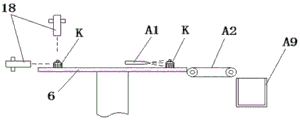
fig. 7 is a schematic front view of a part of the embodiment of the present invention;
fig. 8 is an electrical control schematic block diagram.
The specific implementation mode is as follows:
the present invention will be described in further detail with reference to the accompanying drawings and specific embodiments.
As shown in figures 1-6, the utility model relates to a Christmas ball cap CCD screening device, which comprises a frame 1, the machine frame 1 is provided with a ball cover screening input device and a ball cover screening output device A, the upper end of the machine frame 1 is fixedly provided with a funnel-shaped material box 2 for placing ball covers to be screened, a discharge hole is arranged at the bottom of the material box 2, a feeding hopper 3 is arranged below the discharge hole, the feeding hopper 3 is in a U-groove shape, and inclines to one side of the vibration disk 4, the vibration disk 4 is arranged below the output end of the feeding hopper 3, the vibration disk is a conventional vibration disk, which is output by one element when outputting, the output end of the vibration disk 4 is connected with a ball cover conveying track 5, the output end of the ball cover conveying track 5 is connected with the outer edge of the top surface of a transparent horizontal turntable 6, so that the output ball cover falls on the transparent horizontal turntable 6 driven by a motor to rotate; when the automatic screening machine works, ball covers to be screened in a material box 2 fall into a feeding hopper 3 from a discharge port at the bottom of the material box 2, then fall into a vibrating disc 4 from the output end of the feeding hopper 3, the vibrating disc 4 vibrates and conveys the ball covers one by one, finally the ball covers pass through a ball cover conveying track 5 and are arranged on a conveying belt transparent horizontal turntable 6, the transparent horizontal turntable 6 drives the ball covers to rotate clockwise, and photographing and screening are carried out in the rotating process; the transparent horizontal turntable 6 is provided with at least two groups of high-speed cameras 18 (the high-speed cameras 18 are cameras commonly used in CCD screening equipment) near the side of the spherical cover conveying track 5, and usually three groups of high-speed cameras 18 are provided for shooting the main view, the overlook view and the side view of a product respectively, whether burrs exist on the periphery of the spherical cover can be checked through the three view angles, the spherical cover screening output device A comprises at least two groups of high-pressure air nozzles A1 positioned above the transparent horizontal turntable and an output conveying belt A2 arranged opposite to the high-pressure air nozzles A1, usually two groups of high-pressure air nozzles A1 are provided, one group of air jets is used for picking out defective products, the high-pressure air nozzles A1 are all connected with high-pressure air pipelines, a control valve for controlling air outlet or air closing of the high-pressure air nozzles A1 is provided with a controller, the control valve is controlled to act, the input end of the output conveying belt A2 is, the output end of the output conveying belt is provided with a material containing barrel A3 below, after the high-pressure air nozzle A1 sprays air, the air-sprayed ball cover is blown to the output conveying belt A2, the output conveying belt A2 continuously rotates, and the blown ball cover is conveyed into the material containing barrel A3 below the output end of the output conveying belt.
In this embodiment, the first vibrating device 7 is installed to the bottom of going into hopper 2, the top of vibration dish 4 is equipped with the detection switch 17 that is used for detecting the bulb quantity in the vibration dish 4, detection switch 17 is through a control unit and first vibrating device 7 electric connection.
In this embodiment, as shown in fig. 3 to 5, the detection switch 17 includes a detection seat plate 8 located above the vibration plate 4 and fixedly connected to the frame 1, a vertically penetrating slot hole 9 is formed in the detection seat plate 8, a rotation block 10 is hinged in the slot hole 9, a detection rod 11 is fixedly penetrated through the middle of the rotation block 10, the detection rod 11 is made of a metal material, the lower end of the detection rod 11 extends into the vibration plate 4 and is used for contacting with a spherical cover in the vibration plate 4, and the upper end of the detection rod 11 is tapered; a detection probe 12 with a downward detection port and used for sensing the top of the detection rod is vertically arranged right above the slotted hole 9, and the detection probe 12 is fixedly arranged on the detection seat plate 8 through a connecting plate 13. When having a large amount of ball lids in vibration dish 4, the lower extreme of measuring rod 11 contacts with the ball lid in the vibration dish 4 for measuring rod 11 is in the tilt state, and measuring rod 11 top and measuring probe 12 dislocation, measuring probe 12 can not detect, and so first vibrating device 7 is out of work, and then can not carry new ball lid of waiting to filter towards in the vibration dish 41. When the ball lid quantity in the vibration dish 4 reduces gradually to the lower extreme of detecting rod 11 and does not contact with the ball lid in the vibration dish 4, detecting rod 11 was in vertical state under the action of gravity this moment, test probe 12 detects detecting rod 11 and starts through the first vibrating device 7 of the control unit drive, realizes vibrating the pan feeding, adds in toward vibration dish 4 and treats the screening ball lid. The detection rod capable of swinging is matched with the detection probe, so that the automatic conveying of the ball cover can be realized, and the automation degree is high. Preferably, the control unit can be a common 51-chip microcomputer, and the detection probe can be an existing common photoelectric sensor, an infrared sensor and the like.
In this embodiment, the lower end of the detection rod 11 is fixedly connected with a rubber block 14 which is beneficial to contacting with the spherical cover in the vibration disk 4, and the rubber block is cylindrical. By connecting the rubber block, the detection rod made of metal material is prevented from damaging the ball cover.
In this embodiment, the feeding hopper 3 has a groove-shaped structure with a U-shaped cross section, and the feeding hopper 3 is obliquely arranged and is inclined by 5 degrees toward the vibrating disk 4. In order to facilitate stable conveying of the spherical caps, the first vibrating device 7 is a straight vibrating flat feeder, the bottom of the straight vibrating flat feeder is fixedly installed on the rack 1, and the top of the straight vibrating flat feeder a is fixedly connected with the bottom of the feeding hopper 2. The feeding hopper is vibrated by the direct vibration flat feeder, so that the ball cover in the feeding hopper sequentially moves towards the vibration disc.
In this embodiment, the ball cover conveying track 5 includes a rectangular track body 501, the bottom of the track body 501 is connected with the second vibration device 15, and a sliding groove 502 with an inverted T-shaped cross section is arranged inside the track body 501, as shown in fig. 6; the input end of spout 502 links up with the output end of vibration dish 4, and the output of spout 502 links up with the top surface outward flange of transparent horizontal carousel 6 mutually to do benefit to the spherical cap in the vibration dish 4 and carry to transparent horizontal carousel through the spout on.
In this embodiment, the track body 501 is horizontally disposed, the second vibration device 15 is a straight vibration flat conveyer B, the bottom of the straight vibration flat conveyer B is fixedly mounted on the frame 1, and the top of the straight vibration flat conveyer B is fixedly connected with the bottom of the track body 501. The ball cover conveying track 5 is vibrated by the straight vibration flat conveyer B, so that the ball covers in the ball cover conveying track sequentially move towards the transparent horizontal turntable.
In this embodiment, the transparent horizontal turntable 6 rotates clockwise, the high-speed camera 18 and the high-pressure air nozzle a1 are staggered by 90 to 240 degrees on the circumference, the outlet end of the ball cover conveying rail 5 is taken as a starting point, or called as a first station, the ball cover rotates along with the transparent horizontal turntable 6 and then passes through a station where the high-speed camera 18 is located, called as a second station, and a workpiece is shot in the station; then, the ball cover enters a station where the high-pressure air nozzle A1 is located along with the rotation of the transparent horizontal rotary table 6, the station is called a third station, defective products and good products are removed, and finally some workpieces which are not detected or cannot be detected and judged to be good products or defective products are blocked by the cleaning head A5 and fall into the output guide channel and the charging bucket A9, the station is called a fourth station, the first station and the second station are circumferentially staggered by 140 degrees, the second station and the third station are circumferentially staggered by 110 degrees, the third station and the fourth station are circumferentially staggered by 45 degrees, and the fourth station and the first station are circumferentially staggered by 45 degrees.
In this embodiment, both sides of the output conveyer belt are provided with guard plates a4, the input end of the output conveyer belt is in a cone shape by the two guard plates a4, and the guard plates a4 on both sides of the output conveyer belt are beneficial to preventing the spherical caps from being blown off the conveyer belt by high-pressure air.
In this embodiment, above-mentioned high-pressure air shower nozzle A1 level is unsettled to be set up in the top of transparent horizontal carousel, and the high-pressure air shower nozzle gas outlet is just to the central line position of output conveyer belt, can guarantee better through this design that the spherical cover is blown to the conveyer belt by high-pressure air on, and can not break away from.
In this embodiment, be equipped with two on the surface of above-mentioned transparent horizontal rotary table and drive pivoted cleaning head a5 by the rotating electrical machines, the cleaning head includes rotor a6 with motor a10 output shaft fixed connection and pastes the sponge layer a7 at the rotor lower surface, the lower surface on sponge layer hugs closely on the surface of transparent horizontal rotary table, the direction of rotation of cleaning head and transparent horizontal rotary table is the same, is located the side of transparent horizontal rotary table and just is equipped with output guide way A8 to the cleaning head for output heavy test spare, the output of output guide way is equipped with charging bucket a9, and this cleaning head a 5's sponge layer a7 not only is favorable to blockking the spherical cap, is favorable to cleaning transparent horizontal rotary table 6 moreover, provides clean assurance for transparent horizontal rotary table 6 lasts work.
In this embodiment, above-mentioned high-speed camera 18 respectively with 19 electric connection of controller, the control valve and the controller electric connection of opening and close of high pressure gas shower nozzle, respectively with 19 electric connection of controller through high-speed camera 18, make the ball lid appearance of shooting can input into the controller, compare through the standard photo that prestores in with the controller, obtain the work piece that is not conform to the standard part with the analysis, and then reject through high pressure gas shower nozzle A1 blowout high pressure gas, and when start which high pressure gas shower nozzle, realize through its above-mentioned control valve of opening and close with controller electric connection.
The utility model discloses ball lid CCD sieving mechanism on christmas's theory of operation: in the pan feeding case is put into to the ball lid after injection moulding, then get into in hopper and the vibration dish, then get into in proper order on ball lid delivery track and the transparent horizontal rotary table, along with the clockwise rotation of transparent horizontal rotary table, make the station of ball lid rotatory to high-speed camera on it, shoot by high-speed camera, the picture after the shooting is compared with the picture of original storage, when comparing the back discovery and having deckle edge, by the jet-propelled work of high-pressure gas shower nozzle promptly, make the defective products that has the deckle edge insufflate the output conveyer belt that is used for exporting the defective products, and the non-defective products is insufflated the output conveyer belt that is used for exporting the non-defective products, thereby realize the screening of ball lid.
The above is only the preferred embodiment of the present invention, and all the equivalent changes and modifications made according to the claims of the present invention should be covered by the present invention.
Claims (10)
1. The utility model provides a ball lid CCD sieving mechanism christmas, includes the frame, its characterized in that: the ball cover screening input device comprises a material box fixedly mounted on the upper end of the machine frame and used for placing ball covers to be screened, a discharge port is formed in the bottom of the material box, a feeding hopper is arranged below the discharge port, a vibrating disc is arranged below the output end of the feeding hopper, the output end of the vibrating disc is connected with a ball cover conveying rail, and the output end of the ball cover conveying rail is connected with the outer edge of the top surface of a transparent horizontal turntable so that the output ball covers fall on the transparent horizontal turntable; transparent horizontal rotary table is close to ball lid delivery track's side and is equipped with at least two sets of high-speed cameras, ball lid screening output device is including the output conveyer belt that is located the relative setting of at least two sets of high-pressure gas shower nozzle of transparent horizontal rotary table top and with high-pressure gas shower nozzle, the input of output conveyer belt is close to the edge of transparent horizontal rotary table, the output below of output conveyer belt is equipped with flourishing feed cylinder.
2. The Christmas ball cap CCD screening device of claim 1, wherein: first vibrating device is installed to the bottom of going into the hopper, the top of vibration dish is equipped with the detection switch that is used for detecting ball lid quantity in the vibration dish, detection switch is through a control unit and first vibrating device electric connection.
3. The Christmas ball cap CCD screening device of claim 2, wherein: the detection switch comprises a detection seat plate which is positioned above the vibration disc and fixedly connected with the rack, a vertically-penetrated groove hole is formed in the detection seat plate, a rotating block is hinged in the groove hole, a detection rod is fixedly penetrated through the middle part of the rotating block, and the lower end of the detection rod extends into the vibration disc and is used for being in contact with a ball cover in the vibration disc; the vertical test probe who is equipped with the detection mouth down and is used for responding to the top of measuring stick directly over the slotted hole, when the lower extreme of measuring stick does not contact with the ball lid in the vibration dish, the measuring stick is in vertical state, test probe detects the measuring stick and starts through the first vibrating device of the control unit drive, realizes the vibration pan feeding.
4. The Christmas ball cap CCD screening device of claim 3, wherein: the lower extreme of detection pole is linked firmly so as to be favorable to the rubber block that contacts with the interior ball lid of vibration dish, the rubber block is cylindricly.
5. The Christmas ball cap CCD screening device of claim 2, wherein: the feeding hopper is of a groove-shaped structure with a U-shaped cross section and is horizontally arranged; the first vibrating device is a direct vibrating flat feeder A, the bottom of the direct vibrating flat feeder A is fixedly installed on the rack, and the top of the direct vibrating flat feeder A is fixedly connected with the bottom of the feeding hopper.
6. The Christmas ball cap CCD screening device of claim 1, wherein: the ball cover conveying track comprises a rectangular track body, the bottom of the track body is connected with a second vibrating device, a sliding groove with an inverted T-shaped section is arranged inside the track body, the input end of the sliding groove is connected with the output end of the vibrating disc, and the output end of the sliding groove is connected with the outer edge of the top surface of the transparent horizontal turntable, so that the ball cover in the vibrating disc can be conveyed to the transparent horizontal turntable through the sliding groove; the track body is horizontally arranged, the second vibration device is a direct vibration flat feeder B, the bottom of the direct vibration flat feeder B is fixedly arranged on the rack, and the top of the direct vibration flat feeder B is fixedly connected with the bottom of the track body; the workbin is hourglass hopper-shaped.
7. The Christmas ball cap CCD screening device of claim 1, wherein: the transparent horizontal turntable rotates clockwise, and the high-speed camera and the high-pressure air nozzle are staggered by 90-240 degrees on the circumference.
8. The Christmas ball cap CCD screening device of claim 1, wherein: both sides of the output conveyer belt are provided with guard plates, and the two guard plates are in a conical opening shape at the input end of the output conveyer belt.
9. The Christmas ball cap CCD screening device of claim 1, wherein: the high-pressure air nozzle is horizontally suspended above the transparent horizontal turntable, and the air outlet of the high-pressure air nozzle is over against the central line of the output conveyer belt.
10. The Christmas ball cap CCD screening device of claim 1, wherein: the surface of the transparent horizontal turntable is provided with two cleaning heads driven by a rotating motor to rotate, each cleaning head comprises a rotating sheet fixedly connected with an output shaft of the motor and a sponge layer attached to the lower surface of the rotating sheet, the lower surface of the sponge layer is attached to the surface of the transparent horizontal turntable in a clinging manner, the cleaning heads and the transparent horizontal turntable are in the same steering direction, an output guide channel is arranged beside the transparent horizontal turntable and is opposite to the cleaning heads for outputting a re-inspection part, and the output end of the output guide channel is provided with a charging bucket; the high-speed camera is respectively electrically connected with the controller, and the opening and closing control valve of the high-pressure air nozzle is electrically connected with the controller.
Priority Applications (1)
| Application Number | Priority Date | Filing Date | Title |
|---|---|---|---|
| CN201920793416.1U CN210358131U (en) | 2019-05-29 | 2019-05-29 | Christmas ball cover CCD screening device |
Applications Claiming Priority (1)
| Application Number | Priority Date | Filing Date | Title |
|---|---|---|---|
| CN201920793416.1U CN210358131U (en) | 2019-05-29 | 2019-05-29 | Christmas ball cover CCD screening device |
Publications (1)
| Publication Number | Publication Date |
|---|---|
| CN210358131U true CN210358131U (en) | 2020-04-21 |
Family
ID=70262265
Family Applications (1)
| Application Number | Title | Priority Date | Filing Date |
|---|---|---|---|
| CN201920793416.1U Active CN210358131U (en) | 2019-05-29 | 2019-05-29 | Christmas ball cover CCD screening device |
Country Status (1)
| Country | Link |
|---|---|
| CN (1) | CN210358131U (en) |
Cited By (1)
| Publication number | Priority date | Publication date | Assignee | Title |
|---|---|---|---|---|
| CN114951004A (en) * | 2022-05-23 | 2022-08-30 | 南平华孚电器有限公司 | Current collector optical detection equipment |
-
2019
- 2019-05-29 CN CN201920793416.1U patent/CN210358131U/en active Active
Cited By (1)
| Publication number | Priority date | Publication date | Assignee | Title |
|---|---|---|---|---|
| CN114951004A (en) * | 2022-05-23 | 2022-08-30 | 南平华孚电器有限公司 | Current collector optical detection equipment |
Similar Documents
| Publication | Publication Date | Title |
|---|---|---|
| CN208033068U (en) | A kind of CCD automatic detection devices | |
| CN105402258B (en) | Two station bearing assembly machines | |
| CN105836226B (en) | A kind of cillin bottle appearance and size detection arrangement are started going to a nursery machine | |
| CN108127405A (en) | The automatic package system of injection needle | |
| CN210358131U (en) | Christmas ball cover CCD screening device | |
| CN203356079U (en) | Tea color sorter accurate in feeding | |
| CN211603364U (en) | Waveform testing machine | |
| CN110732488A (en) | Automatic detection screening system for hardware connectors | |
| CN110849892A (en) | FVC outward appearance detection device | |
| CN203816937U (en) | Automatic identification material selecting device for seal caps | |
| CN210358156U (en) | Christmas ball cover screening output device | |
| CN207726975U (en) | A kind of ashing melting machine with automatic sampling detection function | |
| CN207953131U (en) | The automatic package system of injection needle | |
| CN214440988U (en) | Seed sorting device | |
| CN107185847B (en) | Automatic pupa screening device | |
| CN117141778A (en) | Canning equipment and zinc gluconate chewable tablet production facility | |
| CN112317342A (en) | Seed sorting device and method | |
| CN111299137A (en) | Burnt precious stone sorting system based on machine vision | |
| CN209736111U (en) | Capsule sorting unit based on high spectrum technique | |
| CN207964797U (en) | A kind of casing detection machine | |
| CN110568285A (en) | waveform testing machine | |
| CN110721929A (en) | Appearance piece inspection machine | |
| CN114405862B (en) | Method for sorting seeds based on spectral imaging | |
| CN214516060U (en) | Coffee bean autofilter sorter | |
| CN214077923U (en) | CCD intelligence screening installation |
Legal Events
| Date | Code | Title | Description |
|---|---|---|---|
| GR01 | Patent grant | ||
| GR01 | Patent grant |