CN210349563U - Magnetic core mould convenient to dismantle and wash - Google Patents
Magnetic core mould convenient to dismantle and wash Download PDFInfo
- Publication number
- CN210349563U CN210349563U CN201921705074.XU CN201921705074U CN210349563U CN 210349563 U CN210349563 U CN 210349563U CN 201921705074 U CN201921705074 U CN 201921705074U CN 210349563 U CN210349563 U CN 210349563U
- Authority
- CN
- China
- Prior art keywords
- core
- punch
- fixing plate
- die
- fixed
- Prior art date
- Legal status (The legal status is an assumption and is not a legal conclusion. Google has not performed a legal analysis and makes no representation as to the accuracy of the status listed.)
- Expired - Fee Related
Links
- 238000007789 sealing Methods 0.000 claims description 9
- 238000003466 welding Methods 0.000 claims description 6
- 239000000853 adhesive Substances 0.000 claims description 4
- 230000001070 adhesive effect Effects 0.000 claims description 4
- 238000007493 shaping process Methods 0.000 abstract 1
- 238000004140 cleaning Methods 0.000 description 9
- 238000004519 manufacturing process Methods 0.000 description 7
- 238000009434 installation Methods 0.000 description 3
- UQSXHKLRYXJYBZ-UHFFFAOYSA-N Iron oxide Chemical compound [Fe]=O UQSXHKLRYXJYBZ-UHFFFAOYSA-N 0.000 description 2
- 238000000034 method Methods 0.000 description 2
- 238000003723 Smelting Methods 0.000 description 1
- 230000009286 beneficial effect Effects 0.000 description 1
- 238000000071 blow moulding Methods 0.000 description 1
- 238000010586 diagram Methods 0.000 description 1
- 238000004512 die casting Methods 0.000 description 1
- 230000000694 effects Effects 0.000 description 1
- 238000001125 extrusion Methods 0.000 description 1
- 238000005242 forging Methods 0.000 description 1
- 238000009776 industrial production Methods 0.000 description 1
- 238000001746 injection moulding Methods 0.000 description 1
- 238000012423 maintenance Methods 0.000 description 1
- 239000000463 material Substances 0.000 description 1
- 229910044991 metal oxide Inorganic materials 0.000 description 1
- 150000004706 metal oxides Chemical class 0.000 description 1
- 239000000203 mixture Substances 0.000 description 1
- 238000000465 moulding Methods 0.000 description 1
- 239000000243 solution Substances 0.000 description 1
- 229910000859 α-Fe Inorganic materials 0.000 description 1
Images


Landscapes
- Moulds For Moulding Plastics Or The Like (AREA)
Abstract
The utility model discloses a magnetic core mould convenient to dismantle abluent, including punch plate, punch plate's internally mounted has punch core fixed plate, fixed fixture block is all installed to punch core fixed plate's both sides, the stopper is installed to the one end of fixed fixture block, the spring is installed to one side of stopper, the internally mounted of spring has the pull rod, the pull piece is installed to the one end of pull rod, punch core fixed plate's internally mounted has punch core, the locating pin is installed to punch core's one end, the screw is installed to punch core's the other end, punch core's inside is provided with the punch type die cavity, the die is installed to punch core's below. The utility model discloses an install fixed fixture block and terrace die core and can wash the quick split of mould, make things convenient for the staff to wash the mould, make things convenient for next time to use, do not influence the shaping of magnetic core, simple structure, convenient operation.
Description
Technical Field
The utility model relates to a magnetic core mould technical field specifically is a abluent magnetic core mould of convenient to detach.
Background
With the rapid development of social and economic, the magnetic core is a sintered magnetic metal oxide composed of various iron oxide mixtures, the ferrite magnetic core is used in coils and transformers of various electronic devices, various molds and tools for obtaining required products by injection molding, blow molding, extrusion, die casting or forging molding, smelting, stamping and other methods are used in the industrial production of molds, in short, the mold is a tool for manufacturing molded articles, the tool is composed of various parts, different molds are composed of different parts, the processing of the shapes of the articles is realized mainly by the change of the physical states of the molded materials, and the magnetic core mold is a mold used for producing the magnetic core.
However, the existing magnetic core die cannot be disassembled when in use, so that the subsequent production is influenced, and the product quality is reduced; thus, the existing requirements are not met, and a magnetic core mold convenient to disassemble and clean is provided for the existing requirements.
SUMMERY OF THE UTILITY MODEL
An object of the utility model is to provide a magnetic core mould convenient to dismantle abluent to current magnetic core mould that proposes in solving above-mentioned background art can't dismantle when using, influences follow-up production, reduces product quality scheduling problem.
In order to achieve the above object, the utility model provides a following technical scheme: the utility model provides a magnetic core mould convenient to dismantle abluent, includes punch plate, punch plate's internally mounted has punch core fixed plate, fixed fixture block is all installed to punch core fixed plate's both sides, the stopper is installed to the one end of fixed fixture block, the spring is installed to one side of stopper, the internally mounted of spring has the pull rod, the piece of drawing is installed to the one end of pull rod, punch core fixed plate's internally mounted has punch core, the locating pin is installed to punch core's one end, the screw is installed to punch core's the other end, punch core's inside is provided with the punch core chamber, the die is installed to punch core's below, the inside of die is provided with the die cavity, die fixed plate is installed in the outside of die.
Preferably, hanging platforms are arranged on two sides of the male die core, and the male die core is connected with the male die core fixing plate through the hanging platforms.
Preferably, a sealing plate is arranged between the male die fixing plate and the female die fixing plate, and the male die fixing plate and the sealing plate are fixed through an adhesive.
Preferably, a plurality of ejector pins are uniformly installed at the bottom end of the female die.
Preferably, the outer side of the female die is completely attached to the inner side of the female die fixing plate, and the female die fixing plate are fixed through the clamping groove.
Preferably, one end of the pull rod is completely attached to one end of the fixed clamping block, and the pull rod is fixed with the fixed clamping block through welding.
Compared with the prior art, the beneficial effects of the utility model are that:
1. the utility model discloses a take off punch plate, the upset for terrace die core makes progress, holds the outside pulling of pull piece with the hand afterwards. The drawing block drives the pull rod and the pull rod to move outwards through the fixed clamping block fixed by welding, the fixed clamping block can compress the spring during movement, the male die core fixing plate is taken down after the fixed clamping block is drawn out of a clamping groove in the side face of the male die core fixing plate, a specific cleaning tool is used for cleaning, the male die core fixing plate is returned according to the original installation after cleaning is completed, the drawing block is loosened, the spring can recover due to the function of losing lining, the spring can push the fixed clamping block back to the original position, the male die core fixing plate is fixed, the male die of the die can be easily disassembled, and cleaning is convenient;
2. the utility model discloses a be divided into two parts with the terrace die of mould, partly be terrace die core, another part is terrace die core fixed plate, when terrace die core appears wearing and tearing because of long-time production in-process, can loosen the screw and dismantle terrace die core, change, reduce cost, convenient maintenance, and do not want to influence actual production.
Drawings
Fig. 1 is a schematic overall structure diagram of the present invention;
FIG. 2 is a schematic overall structure of the present invention;
fig. 3 is a cross-sectional view of the male mold fixing plate of the present invention.
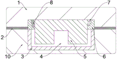
In the figure: 1. a male die fixing plate; 2. a sealing plate; 3. a female die; 4. a female die cavity; 5. a male die core; 6. a male die core fixing plate; 7. a screw; 8. positioning pins; 9. a convex mold cavity; 10. fixing a female die plate; 11. a thimble; 12. drawing the block; 13. a pull rod; 14. a spring; 15. fixing the fixture block; 16. and a limiting block.
Detailed Description
The technical solutions in the embodiments of the present invention will be described clearly and completely with reference to the accompanying drawings in the embodiments of the present invention, and it is obvious that the described embodiments are only some embodiments of the present invention, not all embodiments.
Referring to fig. 1 to fig. 3, the present invention provides an embodiment: a magnetic core die convenient to disassemble and clean comprises a male die fixing plate 1, a male die core fixing plate 6 is installed inside the male die fixing plate 1, fixed clamping blocks 15 are installed on two sides of the male die core fixing plate 6, a limiting block 16 is installed at one end of each fixed clamping block 15, a spring 14 is installed on one side of each limiting block 16, a pull rod 13 is installed inside each spring 14, a drawing block 12 is installed at one end of each pull rod 13, a male die core 5 is installed inside the male die core fixing plate 6, a positioning pin 8 is installed at one end of each male die core 5 for guiding and positioning and fixing at the same time, a screw 7 is installed at the other end of each male die core 5 to facilitate fixing and installing of the male die cores 5, a male die cavity 9 is arranged inside each male die core 5, a female die 3 is installed below each male die core 5, a female die cavity 4, and a female die fixing plate 10 is arranged on the outer side of the female die 3.
Further, the two sides of the male die core 5 are provided with hanging platforms, the male die core 5 is connected with the male die core fixing plate 6 through the hanging platforms, the hanging platforms are convenient for installation and fixation of the male die core 5, and manufacturing is convenient.
Further, a sealing plate 2 is installed between the male die fixing plate 1 and the female die fixing plate 10, the male die fixing plate 1 is fixed with the sealing plate 2 through an adhesive, the sealing performance of the die is guaranteed through the sealing plate 2, the smooth proceeding of the forming is guaranteed, and the adhesive has good connection performance.
Further, a plurality of ejector pins 11 are uniformly installed at the bottom end of the female die 3, and the ejector pins 11 can eject out the formed parts, so that the parts are convenient to take.
Further, the outer side of the female die 3 is completely attached to the inner side of the female die fixing plate 10, the female die 3 is fixed with the female die fixing plate 10 through the clamping groove, the clamping groove is simple in structure, and the female die fixing device is convenient to use and install and replace parts.
Furthermore, one end of the pull rod 13 is completely attached to one end of the fixed fixture block 15, the pull rod 13 is fixed to the fixed fixture block 15 through welding, the connection performance and the stability of the pull rod 13 and the fixed fixture block 15 are enhanced through welding, and the mechanical strength is good.
The working principle is as follows: when the drawing block is used, the mold is firstly opened, the female mold cavity 4 is taken out of the female mold fixing plate 10, the cleaning tool is used for cleaning, the male mold fixing plate 1 is taken down and turned for 180 degrees, the male mold core 5 is enabled to be upward, and then the drawing block 12 is pulled outwards by hands. The drawing block 12 drives the pull rod 13 and the pull rod 13 to move outwards through the fixed fixture block 15 fixed by welding, the fixed fixture block 15 can compress the spring 14 during movement, the male die core fixing plate 6 is taken down after the fixed fixture block 15 is drawn out from a clamping groove in the side surface of the male die core fixing plate 6, the cleaning is carried out by using a specific cleaning tool, the male die core fixing plate 6 is returned according to the original installation after the cleaning is finished, the drawing block 12 is loosened, the spring 14 can recover due to the loss of the internal effect, the spring 14 can push the fixed fixture block 15 back to the original position, the male die core fixing plate 6 is fixed, finally, the parts are returned to the original position one by one, the mold is started for production, the structure is simple, and the operation is.
It is obvious to a person skilled in the art that the invention is not restricted to details of the above-described exemplary embodiments, but that it can be implemented in other specific forms without departing from the spirit or essential characteristics of the invention. The present embodiments are therefore to be considered in all respects as illustrative and not restrictive, the scope of the invention being indicated by the appended claims rather than by the foregoing description, and all changes which come within the meaning and range of equivalency of the claims are therefore intended to be embraced therein. Any reference sign in a claim should not be construed as limiting the claim concerned.
Claims (6)
1. The utility model provides a magnetic core mould convenient to dismantle abluent, includes punch plate (1), its characterized in that: the improved punch core structure is characterized in that a punch core fixing plate (6) is arranged inside the punch fixing plate (1), a fixed clamping block (15) is arranged on two sides of the punch core fixing plate (6), a limiting block (16) is arranged at one end of the fixed clamping block (15), a spring (14) is arranged on one side of the limiting block (16), a pull rod (13) is arranged inside the spring (14), a drawing block (12) is arranged at one end of the pull rod (13), a punch core (5) is arranged inside the punch core fixing plate (6), a positioning pin (8) is arranged at one end of the punch core (5), a screw (7) is arranged at the other end of the punch core (5), a punch mold cavity (9) is arranged inside the punch core (5), a die (3) is arranged below the punch core (5), and a die cavity (4) is arranged inside the die (3), and a female die fixing plate (10) is arranged on the outer side of the female die (3).
2. The magnetic core mold convenient to disassemble and clean as claimed in claim 1, wherein: the two sides of the male die core (5) are provided with hanging tables, and the male die core (5) is connected with the male die core fixing plate (6) through the hanging tables.
3. The magnetic core mold convenient to disassemble and clean as claimed in claim 1, wherein: a sealing plate (2) is arranged between the male die fixing plate (1) and the female die fixing plate (10), and the male die fixing plate (1) and the sealing plate (2) are fixed through an adhesive.
4. The magnetic core mold convenient to disassemble and clean as claimed in claim 1, wherein: and a plurality of ejector pins (11) are uniformly arranged at the bottom end of the female die (3).
5. The magnetic core mold convenient to disassemble and clean as claimed in claim 1, wherein: the outer side of the female die (3) is completely attached to the inner side of the female die fixing plate (10), and the female die (3) is fixed with the female die fixing plate (10) through a clamping groove.
6. The magnetic core mold convenient to disassemble and clean as claimed in claim 1, wherein: one end of the pull rod (13) is completely attached to one end of the fixed clamping block (15), and the pull rod (13) is fixed with the fixed clamping block (15) through welding.
Priority Applications (1)
| Application Number | Priority Date | Filing Date | Title |
|---|---|---|---|
| CN201921705074.XU CN210349563U (en) | 2019-10-12 | 2019-10-12 | Magnetic core mould convenient to dismantle and wash |
Applications Claiming Priority (1)
| Application Number | Priority Date | Filing Date | Title |
|---|---|---|---|
| CN201921705074.XU CN210349563U (en) | 2019-10-12 | 2019-10-12 | Magnetic core mould convenient to dismantle and wash |
Publications (1)
| Publication Number | Publication Date |
|---|---|
| CN210349563U true CN210349563U (en) | 2020-04-17 |
Family
ID=70178483
Family Applications (1)
| Application Number | Title | Priority Date | Filing Date |
|---|---|---|---|
| CN201921705074.XU Expired - Fee Related CN210349563U (en) | 2019-10-12 | 2019-10-12 | Magnetic core mould convenient to dismantle and wash |
Country Status (1)
| Country | Link |
|---|---|
| CN (1) | CN210349563U (en) |
Cited By (1)
| Publication number | Priority date | Publication date | Assignee | Title |
|---|---|---|---|---|
| CN114986667A (en) * | 2022-05-19 | 2022-09-02 | 江苏天瑜新材料科技有限公司 | Soft magnetic ferrite magnetic core forming die convenient to unloading |
-
2019
- 2019-10-12 CN CN201921705074.XU patent/CN210349563U/en not_active Expired - Fee Related
Cited By (2)
| Publication number | Priority date | Publication date | Assignee | Title |
|---|---|---|---|---|
| CN114986667A (en) * | 2022-05-19 | 2022-09-02 | 江苏天瑜新材料科技有限公司 | Soft magnetic ferrite magnetic core forming die convenient to unloading |
| CN114986667B (en) * | 2022-05-19 | 2024-02-27 | 江苏天瑜新材料科技有限公司 | Soft magnetic ferrite magnetic core forming die convenient to unloading |
Similar Documents
| Publication | Publication Date | Title |
|---|---|---|
| CN201784137U (en) | Injection die | |
| CN204585646U (en) | Novel jig of loosing core | |
| CN210349563U (en) | Magnetic core mould convenient to dismantle and wash | |
| CN205735855U (en) | A kind of mould structure of core pulling | |
| CN102059777A (en) | Flexible deformation combined injection molding die for serialized products | |
| CN204075142U (en) | Metal convex-concave housing component die-casting forming die | |
| CN201913780U (en) | Front mould slanted slider drawing structure for injection molding mould | |
| CN205969748U (en) | Integrative mould of five metals plastic | |
| CN211567057U (en) | Forming die manufacturing device | |
| CN208615216U (en) | A kind of mold that mechanism is evaded with bullet formula facilitating operation | |
| CN204220795U (en) | Mould automatic discharging structure | |
| CN207432442U (en) | Refractory material pours mold before a kind of high temperature furnace | |
| CN103551524B (en) | Casting method for multislot belt wheel, core making mold used in casting method and casting mold | |
| CN202727180U (en) | Elbow pipe evanescent molding core | |
| CN209255629U (en) | Carry on the back web plate hanging head blanking die | |
| CN208305721U (en) | A kind of spring ejection stripper apparatus | |
| CN214211938U (en) | Front plate riveting forming die | |
| CN209812992U (en) | Delay slide block | |
| CN210233821U (en) | Monochrome mold for line protection guide rail of automatic equipment | |
| CN210820666U (en) | Push pedal slider internal pulling mechanism | |
| CN212498714U (en) | Mould slide mechanism and mould | |
| CN215825810U (en) | Mould is used in production of line knot | |
| CN209955216U (en) | Complicated oblique position structure of moving of mould around aircraft nose lid | |
| CN209063353U (en) | A kind of upper and lower shell structure of precision long-service die | |
| CN210705807U (en) | Washing machine subassembly injection moulding device |
Legal Events
| Date | Code | Title | Description |
|---|---|---|---|
| GR01 | Patent grant | ||
| GR01 | Patent grant | ||
| CF01 | Termination of patent right due to non-payment of annual fee | ||
| CF01 | Termination of patent right due to non-payment of annual fee |
Granted publication date: 20200417 |