CN210307927U - Round flattening die cutting machine - Google Patents
Round flattening die cutting machine Download PDFInfo
- Publication number
- CN210307927U CN210307927U CN201921314889.5U CN201921314889U CN210307927U CN 210307927 U CN210307927 U CN 210307927U CN 201921314889 U CN201921314889 U CN 201921314889U CN 210307927 U CN210307927 U CN 210307927U
- Authority
- CN
- China
- Prior art keywords
- die cutting
- module
- die
- cutting
- cutting machine
- Prior art date
- Legal status (The legal status is an assumption and is not a legal conclusion. Google has not performed a legal analysis and makes no representation as to the accuracy of the status listed.)
- Active
Links
Images
Abstract
The utility model discloses a rotary flattening die-cutting machine, include: the automatic feeding device comprises a rack, a discharging shaft module, a deviation rectifying module, a traction device, a die cutting module and a receiving shaft module, wherein the discharging shaft module, the deviation rectifying module, the traction device, the die cutting module and the receiving shaft module are arranged on the rack. In this way, the utility model discloses circle flattening die-cutting machine, realize automatic blowing through the pivot of two sides and receive the material, can realize high-speed serialization operation, the production efficiency is improved, position through rectifying module adjustment coiled material, the hypoplastron is motionless, the top cylinder roller is controlled and is removed the cross cutting, the material cross cutting time adopts and compresses tightly, the adsorption mode is fixed to it, high accuracy, height regulating mechanism adjustment cutter height reaches the depth of cut when the cutting die, can be applicable to the coiled material and the different cross cutting processes of different thickness, reliable performance is high, the location is accurate, compact structure, high durability and convenient operation, maintain advantages such as simple and convenient, simultaneously have extensive market prospect in the application and the popularization of cross cutting mechanical production.
Description
Technical Field
The utility model relates to a digit control machine tool knife rest field especially relates to circle flattening die-cutting machine.
Background
The die cutting mode of the circular flattening die cutting machine is that a die cutting material is placed on a plane die cutting plate manually, the position of the die cutting material on a jig is adjusted by manual visual inspection, the die cutting material is not positioned after being placed, the die cutting material is fixed by a locking device, the die cutting material is moved due to the fact that no fixing mode exists in the die cutting process, the rate of finished products is low, die cutting is completed under the driving of the friction force of a transmission device, the die cutting material and waste materials are collected manually after die cutting is completed and accumulated, the labor intensity of workers is high, the production cost is high, the efficiency is low, maintenance and replacement are complicated, and.
SUMMERY OF THE UTILITY MODEL
The utility model discloses the main technical problem who solves provides the rotary flattening die-cutting machine.
In order to solve the technical problem, the utility model discloses a technical scheme be:
providing a rotary ironing die-cutting machine comprising: the automatic material receiving and feeding device comprises a rack, a material discharging shaft module, a deviation rectifying module, a traction device, a die cutting module and a material receiving shaft module, wherein the material discharging shaft module is arranged on the rack and used for discharging materials in a tension output mode, the deviation rectifying module is used for ensuring that a coiled material is always led out from a set position in the material discharging process, the traction device is used for ensuring that the coiled material is fed when the current position of the coiled material is die-cut and tensioning the coiled material at a die cutting station, the die cutting module is used for performing circular.
In a preferred embodiment of the present invention, the discharging shaft module includes a rotating shaft driven by a servo motor and extending in a horizontal direction.
In a preferred embodiment of the present invention, the number of the discharging shaft modules is 2 and the respective rotating shafts are parallel to each other.
In a preferred embodiment of the present invention, the drawing devices are respectively disposed at drawing stations at two ends of the die cutting module.
In a preferred embodiment of the present invention, the traction device comprises parallel traction rollers rotating relatively.
In a preferred embodiment of the present invention, the die-cutting module includes a movable die-cutting roller module, a die-cutting tool, a tool height adjusting mechanism, and a suction cup module disposed at a die-cutting station.
In a preferred embodiment of the present invention, the movable die-cutting roller module includes a rail along the die-cutting direction, and a die-cutting cylindrical roller moving along the die-cutting direction.
In a preferred embodiment of the present invention, the die cutting tool is embedded in the jig of the die cutting station.
In a preferred embodiment of the present invention, the cutter height adjusting mechanism includes a motor for driving the die cutting cutter to move in a vertical direction.
In a preferred embodiment of the present invention, the pressing module is disposed at two ends of the die-cutting station.
The utility model has the advantages that: the utility model provides a circle flattening die-cutting machine, realize automatic blowing through the pivot of two sides and receive the material, can realize high-speed serialization operation, the production efficiency is improved, through the position of the module adjustment coiled material of rectifying, the hypoplastron is motionless, the top cylinder roller is controlled and is removed the side and remove and carry out the cross cutting, adopt to compress tightly during the material cross cutting, the adsorption mode is fixed it, high accuracy, height control mechanism adjustment cutter height and the depth of cut when cutting the mould, can be applicable to the coiled material and the different cross cutting processes of different thickness, reliable performance is high, the location is accurate, compact structure, high reliability, convenient operation, maintain advantages such as simple and convenient, the while has extensive market prospect in the application and the popularization of cross cutting.
Drawings
In order to more clearly illustrate the technical solutions of the embodiments of the present invention, the drawings used in the description of the embodiments are briefly introduced below, and it is obvious that the drawings in the following description are only some embodiments of the present invention, and for those skilled in the art, other drawings can be obtained without inventive work, wherein:
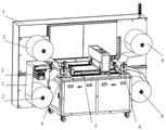
FIG. 1 is a schematic view of the overall structure of a preferred embodiment of the rotary die-cutting machine of the present invention;
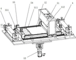
fig. 2 is a schematic structural view of a traction device and a die cutting module of a preferred embodiment of the rotary die cutting machine of the present invention.
Detailed Description
The technical solutions in the embodiments of the present invention will be described clearly and completely below, and it should be apparent that the described embodiments are only some embodiments of the present invention, but not all embodiments. Based on the embodiments in the present invention, all other embodiments obtained by a person skilled in the art without creative efforts belong to the protection scope of the present invention.
Referring to fig. 1 to 2, an embodiment of the present invention includes:
a rotary flattening die cutter comprising: the automatic material-receiving machine comprises a frame 1, a discharging shaft module 2, a deviation-rectifying module 3, a traction device 4, a die-cutting module 5 and a material-receiving shaft module 6, wherein the discharging shaft module, the deviation-rectifying module 3, the traction device 4, the die-cutting module and the material-receiving shaft module are arranged on the frame 1.
The emptying shaft module 2 and the receiving shaft module 6 are respectively arranged at the front end and the rear end of the die cutting module 5, the traction devices 4 are respectively arranged at the front end and the rear end of the die cutting module 5, and the coiled material 7 on the emptying shaft module 2 sequentially passes through the deviation rectifying module 3, the traction device 4 at the front end, the die cutting module 5, the traction device 4 at the rear end and the receiving shaft module 6.
The baiting shaft module 2 comprises a rotating shaft for placing the horizontal direction of the coiled material 7, two baiting shaft modules 2 are arranged in the vertical direction, the respective rotating shafts are parallel to each other, one baiting shaft module 2 can place another coiled material 7 or an auxiliary material, the coiled material 7 of the other baiting shaft module 2 synchronously enters the die cutting module 5 for die cutting, the rotating shaft is driven by a servo motor to rotate, and the tension matching through the traction device 4 realizes that the coiled material 7 is stably output and enters the deviation rectifying module 3.
The parameters of the deviation rectifying module 3 are preset, so that the coiled material 7 is ensured to be led out from the set position all the time in the unreeling process, the output position of the coiled material 7 is limited, and the coiled material can accurately enter a die cutting station.
The die cutting module 5 comprises a movable die cutting roller module 51, a die cutting cutter 52, a cutter height adjusting mechanism 53, a suction cup module 54 and a pressing module 55 which are arranged at a die cutting station.
The movable die cutting roller module 51 comprises a track 511 and a die cutting cylindrical roller 512, wherein the track 511 is arranged on two sides of the die cutting jig, the die cutting cylindrical roller 512 spans the die cutting jig in a bridge mode, and the servo motor drives the die cutting cylindrical roller 512 to move back and forth along the track 511 so as to die cut the coiled material 7 on the die cutting jig.
The die cutting tool 52 is embedded in a jig of a die cutting station, the tool height adjusting mechanism 53 comprises a motor for driving the die cutting tool 52 to move along the vertical direction, the motor drives the die cutting tool 52 to extend out during die cutting, and the motor drives the die cutting tool 52 to retract after the die cutting is finished.
The sucking disc module 54 comprises an air hole and an air cylinder which are arranged on the die cutting jig, and can adsorb the die cutting coiled material 7 to be flat and tightly attached to a cutter, so that the die cutting of the cutter is smoother and more accurate.
The pressing modules 55 are respectively arranged at two ends of the die cutting station, each pressing module 55 comprises a pressing plate 551 and a pressing motor, the pressing motor drives the pressing plate 551 to move along the vertical direction, and when die cutting is needed, the pressing motor presses the pressing plates 551 down to firmly fix two ends of the coiled material 7 and prevent the coiled material 7 from shifting during die cutting.
Receive material axle module 6 including the pivot of the horizontal direction of receiving the material, set up two and receive material axle module 6 in vertical direction to respective pivot is parallel to each other, and one of them receives material axle module 6 and can collect the coiled material 7 that has cross cutting, and another kind of coiled material 7 or the auxiliary material that has cross cutting can be collected to another receipts material axle module 6, and servo motor drive pivot rotates, realizes stably collecting through draw gear 4's tension cooperation.
The working principle is as follows: the discharging shaft module 2 discharges materials, the coiled materials 7 pass through the deviation rectifying module 3 and are guided out according to a preset position to enter the traction device 4 at the front end, pass through the compression module 55 at the front end after passing through the traction device 4, pass through the die cutting jig and are guided out from the lower part of the movable die cutting roller module 51, pass through the compression module 55 at the rear end, finally enter the traction device 4 at the rear end, the traction devices 4 at the front end and the rear end are adjusted to ensure that the die cutting coiled materials 7 keep a certain tension, the sucking disc module 54 works to adsorb the coiled materials 7 to be flat, the pressing plate 551 presses down and fixes the die cutting coiled materials 7, the cutter height adjusting mechanism 53 adjusts the extending height of the die cutting tools 52, the movable die cutting roller module 51 moves along the track 511 to carry out die cutting, after the die cutting is finished, the sucking disc module 54 stops adsorbing, the pressing plate 551 ascends to remove and, and repeating the working procedures and carrying out next die cutting.
The utility model discloses flat cross cutting machine's beneficial effect is: the utility model provides a circle flattening die-cutting machine, realize automatic blowing through the pivot of two sides and receive the material, can realize high-speed serialization operation, the production efficiency is improved, through the position of the module adjustment coiled material of rectifying, the hypoplastron is motionless, the top cylinder roller is controlled and is removed the side and remove and carry out the cross cutting, adopt to compress tightly during the material cross cutting, the adsorption mode is fixed it, high accuracy, height control mechanism adjustment cutter height and the depth of cut when cutting the mould, can be applicable to the coiled material and the different cross cutting processes of different thickness, reliable performance is high, the location is accurate, compact structure, high reliability, convenient operation, maintain advantages such as simple and convenient, the while has extensive market prospect in the application and the popularization of cross cutting.
The above only is the embodiment of the present invention, not limiting the patent scope of the present invention, all of which utilize the equivalent structure or equivalent flow transformation made by the content of the specification of the present invention, or directly or indirectly applied to other related technical fields, all included in the same way in the patent protection scope of the present invention.
Claims (10)
1. Round flattening die-cutting machine, its characterized in that includes: the automatic material receiving and feeding device comprises a rack, a material discharging shaft module, a deviation rectifying module, a traction device, a die cutting module and a material receiving shaft module, wherein the material discharging shaft module is arranged on the rack and used for discharging materials in a tension output mode, the deviation rectifying module is used for ensuring that a coiled material is always led out from a set position in the material discharging process, the traction device is used for ensuring that the coiled material is fed when the current position of the coiled material is die-cut and tensioning the coiled material at a die cutting station, the die cutting module is used for performing circular.
2. The rotary platen die cutting machine according to claim 1, wherein the discharge shaft module includes a servo motor driven horizontally rotating shaft.
3. The rotary platen die cutting machine according to claim 2, wherein the number of the discharging shaft modules is 2 and the respective rotating shafts are parallel to each other.
4. The rotary platen die cutting machine according to claim 1, wherein the drawing devices are respectively disposed at drawing stations at both ends of the die cutting die set.
5. The rotary platen die cutter according to claim 1, wherein the traction means comprises parallel traction rollers that rotate relative to each other.
6. The rotary platen die cutting machine of claim 1, wherein the die cutting modules include a moving die cutting roller module, a die cutting knife, a knife height adjustment mechanism, a suction cup module disposed at a die cutting station.
7. The rotary platen die cutting machine of claim 6, wherein the moving die cutting roller module includes a rail along the die cutting direction, a die cutting cylindrical roller moving along the die cutting direction.
8. The rotary platen die cutting machine according to claim 6, wherein the die cutting tool is mounted flush on a jig of the die cutting station.
9. The rotary platen die cutting machine of claim 6, wherein the cutter height adjustment mechanism includes a motor that drives the die cutting cutter in a vertical direction.
10. The rotary platen die cutting machine of claim 1, further comprising compression modules disposed at opposite ends of the die cutting station.
Priority Applications (1)
| Application Number | Priority Date | Filing Date | Title |
|---|---|---|---|
| CN201921314889.5U CN210307927U (en) | 2019-08-14 | 2019-08-14 | Round flattening die cutting machine |
Applications Claiming Priority (1)
| Application Number | Priority Date | Filing Date | Title |
|---|---|---|---|
| CN201921314889.5U CN210307927U (en) | 2019-08-14 | 2019-08-14 | Round flattening die cutting machine |
Publications (1)
| Publication Number | Publication Date |
|---|---|
| CN210307927U true CN210307927U (en) | 2020-04-14 |
Family
ID=70129780
Family Applications (1)
| Application Number | Title | Priority Date | Filing Date |
|---|---|---|---|
| CN201921314889.5U Active CN210307927U (en) | 2019-08-14 | 2019-08-14 | Round flattening die cutting machine |
Country Status (1)
| Country | Link |
|---|---|
| CN (1) | CN210307927U (en) |
-
2019
- 2019-08-14 CN CN201921314889.5U patent/CN210307927U/en active Active
Similar Documents
| Publication | Publication Date | Title |
|---|---|---|
| CN101575797B (en) | Semi-automatic double-pole umbrella fabric pressure cutting machine | |
| CN209097672U (en) | A kind of continuous blanking type reason piece equipment | |
| CN108724333A (en) | A kind of full automatic high efficiency die-cutting machine | |
| CN210307927U (en) | Round flattening die cutting machine | |
| CN219465100U (en) | Processing cutting equipment for hollow plastic plate | |
| CN208946348U (en) | A kind of multi-functional die-cutting machine of full-automation | |
| CN217095971U (en) | Automatic bi-polar saw of business turn over material | |
| CN206242262U (en) | Battery carbon felt robotic cutting device | |
| CN115783867A (en) | Device for gluing and sticking sheet | |
| CN112659254B (en) | Rubber pad part punching machine | |
| CN210336189U (en) | Automatic shell punching machine device of soft package lithium battery | |
| CN211336712U (en) | Food package bag conveyor | |
| CN210757912U (en) | Guillootine convenient to fixed raw materials | |
| CN110340952A (en) | Circle planishing die cutting machine | |
| CN219768505U (en) | Die cutting equipment for coiled material processing | |
| CN220027694U (en) | Stamping device with garbage collection | |
| CN218195528U (en) | Automatic feeding structure of glue stamping machine with positioning mechanism | |
| CN215360371U (en) | Film pasting device for stainless steel plate | |
| CN217947132U (en) | Delivery unit | |
| CN215047364U (en) | Test paper strip feed mechanism | |
| CN218855157U (en) | Rigging machine garbage collection device | |
| CN212398301U (en) | Feeding device for gate type plate shearing machine | |
| CN217531104U (en) | Full-automatic sheet punching machine | |
| CN211362530U (en) | Cross cutting garbage collection platform | |
| CN220313560U (en) | Full-automatic punching machine |
Legal Events
| Date | Code | Title | Description |
|---|---|---|---|
| GR01 | Patent grant | ||
| GR01 | Patent grant |