CN210287778U - Waterproof printing and dyeing cleaning table for textile fabric - Google Patents
Waterproof printing and dyeing cleaning table for textile fabric Download PDFInfo
- Publication number
- CN210287778U CN210287778U CN201921117323.3U CN201921117323U CN210287778U CN 210287778 U CN210287778 U CN 210287778U CN 201921117323 U CN201921117323 U CN 201921117323U CN 210287778 U CN210287778 U CN 210287778U
- Authority
- CN
- China
- Prior art keywords
- pipe
- fixedly connected
- workstation
- communicates
- workbench
- Prior art date
- Legal status (The legal status is an assumption and is not a legal conclusion. Google has not performed a legal analysis and makes no representation as to the accuracy of the status listed.)
- Active
Links
Images
Landscapes
- Treatment Of Fiber Materials (AREA)
Abstract
The utility model discloses a textile fabric waterproof printing and dyeing cleaning table, which comprises a workbench, wherein an immersion groove is embedded in one end of the top of the workbench, the two sides of the inner wall of the immersion groove are respectively fixedly connected with the two ends of a pressing rod, the middle parts of the two sides of the top of the workbench are respectively fixedly connected with the two ends of the bottom of a connecting frame, the top of the connecting frame is alternately connected with the middle part of a first communicating pipe, a separation net is embedded in the center of the top of the workbench, the two sides of one end of the workbench are respectively fixedly connected with one ends of two connecting rods, and the other end of one connecting rod is rotatably connected with one end of a material roller through a rotating shaft; by arranging the structures such as the water suction roller and the like, redundant water on the surface of the cloth is removed, and the subsequent processing is facilitated.
Description
Technical Field
The utility model relates to a clean bench, in particular to waterproof printing and dyeing clean bench of textile fabric belongs to printing and dyeing equipment technical field.
Background
In the textile industry, after the cloth is produced, dyeing is needed, the cloth is immersed into liquid dye, the liquid dye and the cloth are stirred to color the cloth, and the dyed cloth needs to be cleaned once to clean the floating color on the surface of the cloth. In the existing workshop, water is generally adopted
The washing method is used for removing the loose color on the surface of the cloth, and the water washing equipment is the key point of water washing. The cleaning effect of the existing cloth washing equipment is not ideal, and after the cloth washing equipment is cleaned, the cloth is curled, folded and contains larger water, so that subsequent processing is not convenient.
SUMMERY OF THE UTILITY MODEL
An object of the utility model is to provide a waterproof printing and dyeing clean bench of textile fabric to the cleaning performance of the current cloth washing equipment who provides in solving above-mentioned background art is unsatisfactory, washs the completion back, and the cloth curls the fold and contains the problem of the follow-up processing of being not convenient for of great moisture.
In order to achieve the above object, the utility model provides a following technical scheme: a textile fabric waterproof printing and dyeing cleaning table comprises a workbench, wherein an immersion groove is embedded in one end of the top of the workbench, two sides of the inner wall of the immersion groove are fixedly connected with two ends of a pressing rod respectively, the middle parts of two sides of the top of the workbench are fixedly connected with two ends of the bottom of a connecting frame respectively, the top of the connecting frame is connected with the middle part of a first communicating pipe in an inserting manner, a separation net is embedded in the center of the top of the workbench, two sides of one end of the workbench are fixedly connected with one end of two connecting rods respectively, the other end of one connecting rod is rotatably connected with one end of a material roller through a rotating shaft, the other end of the material roller is fixedly connected with one end of a transmission rod, the other end of the transmission rod penetrates through the other end of the other connecting rod and is fixedly connected with the output end of a driving motor, and one, one side of the top of the supporting plate is in contact connection with the bottom of the driving motor, the middle part of one end of the inner wall of the workbench is in interpenetration connection with the middle part of the water inlet pipe, one end of the water inlet pipe is communicated with the water inlet of the water pump, the water outlet of the water pump is communicated with one end of the water outlet pipe, one side of one end of the water outlet pipe is communicated with one end of a water supply pipe, the other end of the water supply pipe penetrates through the middle part of one side of the workbench and is communicated with one end of a first communicating pipe, the top of one end of the water outlet pipe is communicated with the bottom of the second communicating pipe, one side of the first communicating pipe and one side of the second communicating pipe are both connected with a plurality of uniformly distributed nozzles in an inserting way, the bottom of one end of the inner wall of the workbench is fixedly connected with one end of the drainage plate, the bottom of one end of the workbench is provided with a water outlet, the bottom of delivery port one side and the other end fixed connection of drainage plate, driving motor and water pump are all through external switch and power electric connection.
As a preferred technical scheme of the utility model, the equal fixedly connected with connecting plate of one end of workstation top both sides, two connecting plate tops and bottom are rotated through the both ends of a plurality of pivot and a plurality of evenly distributed's suction roll respectively and are connected.
As an optimal technical scheme of the utility model, the one end at workstation top and one side of link are all fixed and are equipped with the clamp plate, two logical groove has all been seted up to the bottom of clamp plate.
As a preferred technical scheme of the utility model, the outlet has been seted up to the bottom in soaking groove, the inside block in outlet is connected with the sealing plug, the one end in soaking groove communicates with each other with the one end of water injection pipe, the other end of water injection pipe communicates with each other with the middle part of outlet pipe, the middle part fixed mounting of water injection pipe has the valve, the other end of workstation one side and one side fixed connection of adjust knob are passed to the fixed regulation post that sets up in valve top.
As an optimized technical scheme of the utility model, a plurality of the suction roll is made of sponge material.
Compared with the prior art, the beneficial effects of the utility model are that: the utility model relates to a waterproof printing and dyeing cleaning table for textile fabrics, which has the advantages of full and uniform fabric cleaning, high cleaning speed and good effect, and ensures the fabric to keep straight in the cleaning process by arranging structures such as a pressing plate and a pressing rod, thereby ensuring the stability of the processing speed; by arranging the structures such as the water suction roller and the like, redundant water on the surface of the cloth is removed, and the subsequent processing is facilitated.
Drawings
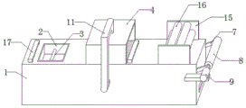
FIG. 1 is a perspective view of the present invention;
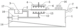
fig. 2 is a structural sectional view of the present invention.
In the figure: 1. a work table; 2. a soaking tank; 3. pressing the rod; 4. a connecting frame; 5. a first communication pipe; 6. separating the net; 7. a connecting rod; 8. a material roller; 9. a drive motor; 10. a water pump; 11. a water supply pipe; 12. a second communicating pipe; 13. a spray head; 14. a drainage plate; 15. a connecting plate; 16. a suction roll; 17. and (7) pressing a plate.
Detailed Description
The technical solutions in the embodiments of the present invention will be described clearly and completely with reference to the accompanying drawings in the embodiments of the present invention, and it is obvious that the described embodiments are only some embodiments of the present invention, not all embodiments. Based on the embodiments in the present invention, all other embodiments obtained by a person skilled in the art without creative work belong to the protection scope of the present invention.
Referring to fig. 1-2, the utility model provides a textile fabric waterproof printing and dyeing cleaning table, which comprises a workbench 1, wherein an immersion groove 2 is embedded at one end of the top of the workbench 1, two sides of the inner wall of the immersion groove 2 are respectively fixedly connected with two ends of a pressure roller 3, the middle parts of two sides of the top of the workbench 1 are respectively fixedly connected with two ends of the bottom of a connecting frame 4, the top of the connecting frame 4 is connected with the middle part of a first communicating pipe 5 in an inserting way, a separation net 6 is embedded at the center of the top of the workbench 1, two sides of one end of the workbench 1 are respectively fixedly connected with one end of two connecting rods 7, the other end of one connecting rod 7 is rotatably connected with one end of a material roller 8 through a rotating shaft, the other end of the material roller 8 is fixedly connected with one end of a transmission rod, the other end of the transmission rod passes through the other end of the other connecting rod 7 and is fixedly connected with, one side of the top of the supporting plate is in contact connection with the bottom of a driving motor 9, the middle of one end of the inner wall of the workbench 1 is in insertion connection with the middle of a water inlet pipe, one end of the water inlet pipe is communicated with a water inlet of a water pump 10, a water outlet of the water pump 10 is communicated with one end of a water outlet pipe, one side of one end of the water outlet pipe is communicated with one end of a water feeding pipe 11, the other end of the water feeding pipe 11 penetrates through the middle of one side of the workbench 1 to be communicated with one end of a first communicating pipe 5, the top of one end of the water outlet pipe is communicated with the bottom of a second communicating pipe 12, one side of the first communicating pipe 5 and one side of the second communicating pipe 12 are both in insertion connection with a plurality of uniformly distributed spray heads 13, the bottom of one end of the inner wall of the workbench 1 is fixedly connected with one end of a drainage plate 14, the water pump 10 is of the type 50 CYZ-50.
Preferably, the connecting plates 15 are fixedly connected to the two ends of the two sides of the top of the workbench 1, the tops and the bottoms of the two connecting plates 15 are respectively and rotatably connected with the two ends of the water absorbing rollers 16 which are uniformly distributed through a plurality of rotating shafts, redundant moisture on the surface of the cloth is removed, and subsequent processing is facilitated.
Preferably, the pressing plates 17 are fixedly arranged at one end of the top of the workbench 1 and one side of the connecting frame 4, and the through grooves are formed in the bottoms of the two pressing plates 17, so that the cloth keeps straight in the cleaning process, and the stability of the processing speed is guaranteed.
Preferably, the outlet has been seted up to the bottom in soaking groove 2, the inside block of outlet is connected with the sealing plug, the one end in soaking groove 2 communicates with each other with the one end of water injection pipe, the other end of water injection pipe communicates with each other with the middle part of outlet pipe, the middle part fixed mounting of water injection pipe has the valve, the fixed regulation post that sets up in valve top passes the other end and one side fixed connection of adjust knob on one side of the workstation, can change for the inside moisture in respectively soaking groove 2, promote the convenience of using.
Preferably, the plurality of water suction rolls 16 are made of sponge materials, so that a good water suction effect of the water suction rolls 16 is ensured.
When specifically using, the utility model relates to a waterproof printing and dyeing clean bench of textile fabric, the bottom that will treat abluent cloth passes clamp plate 17 in proper order leads to the groove, press the logical groove of 3 bottoms of rod and another clamp plate 17 bottoms, wear out by a plurality of suction roll 16 middle parts again, and open the valve with the rotatory adjust knob of one end fixed connection of material roller 8, start water pump 10, close the valve when soaking groove 2 water is full, start driving motor 9, begin to process, material roller 8 drives the cloth antedisplacement, soak through soaking groove 2, make the separation of superficial look of cloth surface, the rivers that water pump 10 pumps are spout through a plurality of shower nozzle 13, wash simultaneously the two sides of cloth, waste water after the washing is discharged from the delivery port through drainage plate 14, the unnecessary moisture is absorbed by suction roll 16 when the cloth passes through suction roll 16, again by material roller 8 with the cloth.
In the description of the present invention, it should be understood that the indicated orientation or positional relationship is based on the orientation or positional relationship shown in the drawings, and is only for convenience of description and simplification of description, and does not indicate or imply that the indicated device or element must have a particular orientation, be constructed and operated in a particular orientation, and thus should not be construed as limiting the present invention.
In the present invention, unless otherwise explicitly specified or limited, for example, it may be fixedly connected, detachably connected, or integrated; can be mechanically or electrically connected; they may be directly connected or indirectly connected through an intermediate medium, and may be connected through the inside of two elements or in an interaction relationship between two elements, unless otherwise specifically defined, and the specific meaning of the above terms in the present invention will be understood by those skilled in the art according to specific situations.
Although embodiments of the present invention have been shown and described, it will be appreciated by those skilled in the art that changes, modifications, substitutions and alterations can be made in these embodiments without departing from the principles and spirit of the invention, the scope of which is defined in the appended claims and their equivalents.
Claims (5)
1. A textile fabric waterproof printing and dyeing cleaning table comprises a working table (1) and is characterized in that an immersion groove (2) is embedded in one end of the top of the working table (1), two sides of the inner wall of the immersion groove (2) are fixedly connected with two ends of a pressing rod (3) respectively, the middle portions of two sides of the top of the working table (1) are fixedly connected with two ends of the bottom of a connecting frame (4) respectively, the top of the connecting frame (4) is connected with the middle of a first communicating pipe (5) in an inserting mode, a separation net (6) is embedded in the center of the top of the working table (1), two sides of one end of the working table (1) are fixedly connected with one end of two connecting rods (7) respectively, one of the connecting rods (7) is rotatably connected with one end of a material roller (8) through a rotating shaft, and the other end of the material roller (8) is fixedly connected with one end of a transmission rod, the other end of transfer line passes the other end of another connecting rod (7) and the output fixed connection of driving motor (9), the one end of workstation (1) one side and one side fixed connection of backup pad, one side at backup pad top is connected with the bottom contact of driving motor (9), the middle part of workstation (1) inner wall one end alternates with the middle part of inlet tube to be connected, the one end of inlet tube communicates with each other with the water inlet of water pump (10), the delivery port of water pump (10) communicates with each other with the one end of outlet pipe, the one side of outlet pipe one end communicates with each other with the one end of delivery pipe (11), the other end of delivery pipe (11) passes the middle part of workstation (1) one side and communicates with each other with the one end of first communicating pipe (5), the top of outlet pipe one end communicates with each other with the bottom of second communicating pipe (12), one side of first communicating pipe (5) and one side of second communicating pipe (12) all alternate and are connected with a Head (13), the bottom of workstation (1) inner wall one end and the one end fixed connection of drainage plate (14), the delivery port has been seted up to the bottom of workstation (1) one end, the bottom and the other end fixed connection of drainage plate (14) of delivery port one side, driving motor (9) and water pump (10) are all through external switch and power electric connection.
2. The waterproof printing and dyeing washing table of textile fabrics of claim 1, characterized in that: the equal fixedly connected with connecting plate (15) of one end of workstation (1) top both sides, two connecting plate (15) tops and bottom are rotated through the both ends of a plurality of pivot and a plurality of evenly distributed's suction roll (16) respectively and are connected.
3. The waterproof printing and dyeing washing table of textile fabrics of claim 1, characterized in that: one end at the top of the workbench (1) and one side of the connecting frame (4) are both fixedly provided with pressing plates (17), and through grooves are formed in the bottoms of the pressing plates (17).
4. The waterproof printing and dyeing washing table of textile fabrics of claim 1, characterized in that: the bottom of soaking groove (2) has been seted up the outlet, the inside block of outlet is connected with the sealing plug, the one end of soaking groove (2) communicates with each other with the one end of water injection pipe, the other end of water injection pipe communicates with each other with the middle part of outlet pipe, the middle part fixed mounting of water injection pipe has the valve, the other end of workstation (1) one side and one side fixed connection of adjust knob are passed to the fixed regulation post that sets up in valve top.
5. The waterproof printing and dyeing washing table of textile fabrics of claim 2, characterized in that: the water suction rollers (16) are all made of sponge materials.
Priority Applications (1)
| Application Number | Priority Date | Filing Date | Title |
|---|---|---|---|
| CN201921117323.3U CN210287778U (en) | 2019-07-17 | 2019-07-17 | Waterproof printing and dyeing cleaning table for textile fabric |
Applications Claiming Priority (1)
| Application Number | Priority Date | Filing Date | Title |
|---|---|---|---|
| CN201921117323.3U CN210287778U (en) | 2019-07-17 | 2019-07-17 | Waterproof printing and dyeing cleaning table for textile fabric |
Publications (1)
| Publication Number | Publication Date |
|---|---|
| CN210287778U true CN210287778U (en) | 2020-04-10 |
Family
ID=70102663
Family Applications (1)
| Application Number | Title | Priority Date | Filing Date |
|---|---|---|---|
| CN201921117323.3U Active CN210287778U (en) | 2019-07-17 | 2019-07-17 | Waterproof printing and dyeing cleaning table for textile fabric |
Country Status (1)
| Country | Link |
|---|---|
| CN (1) | CN210287778U (en) |
Cited By (1)
| Publication number | Priority date | Publication date | Assignee | Title |
|---|---|---|---|---|
| CN113564831A (en) * | 2021-07-19 | 2021-10-29 | 东台市富安合成材料有限公司 | Extrusion drainage type synthetic leather belt cleaning device |
-
2019
- 2019-07-17 CN CN201921117323.3U patent/CN210287778U/en active Active
Cited By (1)
| Publication number | Priority date | Publication date | Assignee | Title |
|---|---|---|---|---|
| CN113564831A (en) * | 2021-07-19 | 2021-10-29 | 东台市富安合成材料有限公司 | Extrusion drainage type synthetic leather belt cleaning device |
Similar Documents
| Publication | Publication Date | Title |
|---|---|---|
| CN110042586B (en) | Environment-friendly textile fabric printing and dyeing system | |
| CN212529963U (en) | Cleaning device for ship deck | |
| CN211493287U (en) | Printing roller belt cleaning device for printing | |
| CN214244904U (en) | Padder convenient to clean | |
| CN213925386U (en) | Cloth belt cleaning device is used in clothing production | |
| CN106988048A (en) | A kind of weaving dyeing apparatus | |
| CN210287778U (en) | Waterproof printing and dyeing cleaning table for textile fabric | |
| CN111926480A (en) | High-efficient washing case | |
| CN115534517A (en) | Printing roller surface oil stain treatment equipment and treatment method thereof | |
| CN210238030U (en) | Cleaning device for printing and dyeing cloth | |
| CN210394812U (en) | Pre-wetting treatment device for clothes printing and dyeing in early stage | |
| CN111826856A (en) | Continuous rope dyeing washing machine and operation method thereof | |
| CN206768405U (en) | A kind of weaving dyeing apparatus | |
| CN213086328U (en) | Cloth ultrasonic rinsing machine | |
| CN215628700U (en) | Fabric washing device | |
| CN210621157U (en) | Low water consumption polyester textile dyeing apparatus | |
| CN212714097U (en) | Continuous rope dyeing washing machine | |
| CN212670050U (en) | Dyeing apparatus is used in processing of dacron surface fabric | |
| CN210621167U (en) | Cleaning equipment is used in non-woven fabrics production | |
| CN114855382A (en) | Clean energy-saving fabric printing and dyeing process | |
| CN220183599U (en) | Cloth belt cleaning device | |
| CN217662026U (en) | Filter pressing plate cleaning machine | |
| CN213389285U (en) | Multi-soaking multi-rolling high-efficiency water washing tank | |
| CN221117905U (en) | Textile fabric textile production integrated equipment | |
| CN218175329U (en) | Belt cleaning device for textile production |
Legal Events
| Date | Code | Title | Description |
|---|---|---|---|
| GR01 | Patent grant | ||
| GR01 | Patent grant |