CN210281229U - Square pipe welding fixture - Google Patents
Square pipe welding fixture Download PDFInfo
- Publication number
- CN210281229U CN210281229U CN201921230771.4U CN201921230771U CN210281229U CN 210281229 U CN210281229 U CN 210281229U CN 201921230771 U CN201921230771 U CN 201921230771U CN 210281229 U CN210281229 U CN 210281229U
- Authority
- CN
- China
- Prior art keywords
- clamping
- square pipe
- square
- pipe
- block
- Prior art date
- Legal status (The legal status is an assumption and is not a legal conclusion. Google has not performed a legal analysis and makes no representation as to the accuracy of the status listed.)
- Active
Links
Images


Abstract
The utility model provides a square pipe welding jig belongs to welding jig technical field. It has solved the poor technical problem of current square pipe welding machine suitability. This pipe welding jig, including the frame, be equipped with the claw portion that is used for the vertical side of pipe lateral wall of centre gripping on the frame, still be equipped with the push-and-pull rod of vertical extension and the relative frame vertical motion of ability on the frame, the peripheral cover of push-and-pull rod is equipped with the stay tube that is used for side's pipe position sleeve to establish, the lower extreme of stay tube with the frame links firmly, and the outer peripheral face of this push-and-pull rod has a plurality of dovetails that extend along vertical slope, and is a plurality of equal sliding fit has a top stay block in the dovetail, the outer end of top stay block runs through and stretches out the lateral wall of stay tube, works as can drive during the push-and-pull rod vertical motion the relative stay tube of top. The utility model discloses square pipe homoenergetic to different specification and dimension forms and stabilizes effectual centre gripping location, and the suitability is strong.
Description
Technical Field
The utility model belongs to the technical field of welding jig, a square pipe welding jig is related to.
Background
At present, the welding of the square pipe and the square pipe cover plate is finished by argon arc welding without wire filling, and because the product has special requirements on the concentricity of the square pipe and the square pipe cover plate, the efficiency is low and the quality is not ensured by manually adopting a side welding and side correcting mode at present. The quality and the production efficiency are greatly improved by adopting a self-centering automatic clamping fixture and a robot welding technology.
Chinese patent that the publication number is CN204997249U discloses a square pipe welding machine, including frame, square pipe fixing device, square pipe rotating device and at least a set of square pipe welding set, square pipe rotating device sets up on the frame, and its upper end is provided with the rotary platform who is used for placing the flange, square pipe is fixed and lower extreme and flange butt joint through square pipe fixing device, and square pipe welding set sets up in the rotary platform side through a translation device, square pipe welding set disposes welder, welder corresponds with the department of meeting of square pipe, flange, can weld four sides of square pipe respectively through translation device cooperation square pipe rotating device, can accomplish the welding of square pipe and flange.
Above-mentioned structure can realize the automatic weld of square pipe and flange, but its centre gripping positioner can only be to the square pipe product of fixed specification, can not satisfy the welding demand of different square pipe types and the condition of placing, and the suitability is poor. However, in the art, in order to solve the problem of clamping applicability, the clamping range is often expanded, for example, the clamping mode and direction of the positioning block are changed or a plurality of stages of step clamping grooves are arranged at the bottom of the upper pressing table, so as to improve the size range of clamping.
Disclosure of Invention
The utility model discloses to the above-mentioned problem that prior art exists, provide a square pipe welding jig, the utility model aims to solve the technical problem that: how to improve the applicability of square tube welding.
The purpose of the utility model can be realized by the following technical proposal:
the utility model provides a square pipe welding jig, includes the frame, be equipped with the claw portion that is used for the vertical side of centre gripping pipe lateral wall of pipe on the frame, its characterized in that, still be equipped with the push-and-pull rod of vertical extension and the relative frame vertical motion of ability on the frame, the peripheral cover of push-and-pull rod is equipped with the stay tube that is used for square pipe position sleeve to establish, the lower extreme of stay tube with the frame links firmly, and the outer peripheral face of this push-and-pull rod has a plurality of dovetails that extend along vertical slope, and is a plurality of equal sliding fit has a supporting block in the dovetail, the outer end of supporting block runs through and stretches out the lateral wall of stay tube works as can drive during the push-and-pull rod vertical motion the supporting block is relative.
The square pipe is when welding with square pipe cover plate, with square vertical setting on the frame, clamping jaw portion carries out the centre gripping to square pipe from outside and makes it keep stable with square pipe cover plate's relative position, then welding gun equipment carries out accurate welding to the square pipe of location and square pipe cover plate, realizes welding process. The supporting tubes are sleeved on the periphery of the push-pull rod, the supporting blocks extending out of the supporting tubes are slidably connected in dovetail grooves formed in the outer peripheral surface of the push-pull rod, the supporting tubes can preliminarily position the square tubes, the square tubes are prevented from being overturned by external force before being clamped, when the push-pull rod is controlled to move vertically, the supporting blocks can gradually move outwards under the force component in the horizontal direction and the limiting effect of the supporting tubes, the supporting blocks can abut against the inner side wall of the square tubes, meanwhile, the supporting blocks can be matched with the clamping jaw parts on the outer side to form positioning clamping from the inner side and the outer side of the square tubes, stable and effective clamping and positioning can be formed by controlling the strokes of the push-pull rod for the square tubes with different specifications and sizes, and the applicability of a welding fixture is improved.
In foretell side's pipe welding jig, the top vaulting piece includes slider and roof, the slider with dovetail sliding fit, one side of roof can be dismantled with this slider and be connected, and the opposite side of this roof can be leaned on with the laminating top of the inside wall of square pipe. Including slider and roof through setting up the top vaulting piece, and make roof and slider be for dismantling the cooperation, can choose for use the roof assembly to the slider of corresponding size to the side pipe of different specification and dimension like this to guarantee location centre gripping effect, further improve the suitability.
In the square pipe welding fixture, the clamping jaw part comprises two clamping heads which can horizontally move in opposite directions, the right side faces of the clamping heads are provided with right-angle clamping grooves, the inner side walls of the right-angle clamping grooves can be attached to the two side walls adjacent to the periphery of the square pipe, and the height positions of the clamping heads correspond to the height positions of the supporting blocks. Include two just to just and can follow the chuck of horizontal direction relative motion through setting up clamping jaw portion, and set up on the chuck can with the right angle complex right angle draw-in groove of square pipe, the lateral wall of two right angle draw-in grooves can be respectively with the four sides laminating supports of square pipe periphery after accomplishing the centre gripping like this, guarantee the centre gripping effect, the high position that sets up the chuck is corresponding with the high position of top kicking block, the clamping-force of both sides can be used on the same section of square pipe like this, it is higher to set up at this section welded square tube cover plate concentricity like this.
As another scheme, the clamping jaw portion includes two chucks capable of moving horizontally and oppositely, each chuck includes a first clamping block, a second clamping block and a driving arm capable of moving along the horizontal direction, the first clamping block is provided with a first inclined surface, the second clamping block is provided with a second inclined surface, the first clamping block on any chuck is opposite to the second clamping block on the other chuck along the moving direction of the chuck, the first clamping block is fixedly connected with the driving arm, the driving arm is fixedly connected with a plurality of guide shafts extending along the moving direction, the second clamping block is slidably connected with the plurality of guide shafts, the periphery of each guide shaft is sleeved with a pressure spring, two ends of each pressure spring are respectively abutted against the driving arm and the second clamping block, and when the square pipe is clamped, a right-angle clamping groove used for abutting against two adjacent side walls of the periphery of the square pipe can be formed between the first inclined surface and. For some square tubes with larger specification and size, the angle of the square tube cannot be completely matched with the angle of the chuck or the top support block after the square tube is sleeved to the periphery of the support tube, and even an included angle close to 45 degrees can be formed, so that when the chuck and the top support block clamp the square tube, under the influence of certain friction force, the inner side wall and the outer side wall of the square tube respectively form line contact with the chuck and the top support block, the integral clamping state of the square tube is very unstable, and a welding gun is difficult to position; the clamping head comprises a first clamping block, a second clamping block and a driving arm which can move along the horizontal direction, the first clamping block is fixedly connected with the driving arm, the second clamping block is connected with the driving arm in a sliding mode through a guide shaft, a pressure spring which can control the position of the second clamping block is sleeved on the periphery of the guide shaft, the first clamping block and the second clamping block on one clamping head are respectively opposite to the second clamping block and the first clamping block on the other clamping head along the horizontal direction, therefore, in an initial state, the second clamping block can exceed a certain distance relative to the first clamping block under the action of the pressure spring, even if the placing angle of an initial square tube is the condition, when the clamping head approaches the square tube, the second inclined plane on the second clamping block can firstly contact with one edge of the square tube, and the edge corresponding to the first inclined plane on the square tube is not contacted with the first inclined plane, so that the square tube can gradually rotate due to different loads on two sides, and the pressure spring is finally compressed in place, and, and two clamp splice two act on the square tube jointly from both sides, further ensure that square pipe smoothly rotates the adjustment to place the square pipe homoenergetic of initial placement and realize effectual centre gripping location to arbitrary angle, improve the suitability.
In foretell square pipe welding jig, the bottom of right angle draw-in groove has the groove of stepping down of vertical extension. The bottom through at the right angle draw-in groove sets up the groove of stepping down of vertical extension, and the groove of stepping down can provide the stepping down for the right angle edge of square pipe like this to improve the laminating effect of the inside wall of right angle draw-in groove and the lateral wall of square pipe.
In the square pipe welding jig, the upper end face of the support pipe is provided with a positioning pin for positioning the square pipe cover plate. Through setting up the locating pin at the upper end terminal surface of stay tube, set up the locating hole in welding the place ahead pipe cover plate center like this and can realize the spacing of square pipe cover plate with the locating pin cooperation to make the position of square pipe cover plate and square pipe relatively stable, guarantee the welding effect.
In the square pipe welding jig, the lifting table for supporting the square pipe is sleeved on the periphery of the supporting pipe, the lifting table can slide up and down along the supporting pipe, the outer peripheral surface of the lifting table is in threaded connection with the positioning bolt extending along the radial direction, and the inner end of the positioning bolt can be abutted against the outer side wall of the supporting pipe. The lifting platform capable of sliding up and down is sleeved on the periphery of the supporting pipe, the lower end of the square pipe can be supported on the lifting platform, and the positioning bolt is arranged on the outer peripheral surface of the lifting platform, so that the welding operation can be realized at the most appropriate position by adjusting the position of the lifting platform for the square pipes with different lengths, and the applicability is further improved.
In the square tube welding fixture, the base is provided with the jacking table, the jacking table is provided with the telescopic arm capable of moving vertically, and the telescopic arm is connected with the pressure head capable of vertically rightly facing the supporting tube. Through set up the roof pressure platform on the frame to but set up vertical motion's flexible arm on the roof pressure platform, and connect on flexible arm and stay tube vertical just right pressure head, like this when square tube cover plate installation back, pressure head roof pressure makes its position stable to square tube cover plate surface when steerable flexible arm downstream, thereby guarantees welding effect and suitability.
In foretell square pipe welding jig, the lower extreme of pressure head is the loudspeaker form, and the lower extreme mask of this pressure head has the constant head tank that is used for the holding the locating pin. The lower extreme through setting up the pressure head is the loudspeaker form, can improve the pressure head and square tube cover plate's application range, improves and compresses tightly the effect, sets up the constant head tank through the lower terminal surface at the pressure head, can avoid locating pin and pressure head to interfere like this, guarantees to compress tightly the effect.
In the square tube welding jig, the jacking table is connected with the base in a sliding manner along the horizontal direction. Can slide along the horizontal direction on the frame through setting up the top pressure platform, like this when welding completion back flexible arm lifting segment distance earlier, then the top pressure platform can realize smoothly unloading of square pipe at the certain distance of horizontal migration, avoids the design length overlength of flexible arm to make overall structure compact inadequately when unloading.
Compared with the prior art, the utility model has the advantages as follows:
1. according to the square pipe welding fixture, the vertical push-pull rod capable of vertically moving relative to the base is arranged on the base, the supporting pipe is sleeved on the periphery of the push-pull rod, the supporting block extending out of the supporting pipe is slidably connected in the dovetail groove formed in the outer peripheral surface of the push-pull rod, the supporting pipe can preliminarily position the square pipe, the square pipe is prevented from being overturned by external force before being clamped, when the push-pull rod is controlled to vertically move, the supporting block can gradually move outwards due to the component force in the horizontal direction and the limiting effect of the supporting pipe, the supporting block can be abutted against the inner side wall of the square pipe, meanwhile, the supporting block can be matched with the clamping jaw in the outer side to form positioning clamping from the inner side pipe and the outer side pipe, stable and effective clamping positioning can be formed by controlling the stroke of the push-pull.
2. This square pipe welding jig establishes gliding elevating platform from top to bottom through the peripheral cover at the stay tube, and the lower extreme of square pipe can support on the elevating platform to set up positioning bolt at the outer peripheral face of elevating platform, can be that it realizes welding operation in the most suitable position through adjusting the position of elevating platform to the square pipe of different length like this, further improve the suitability.
Drawings
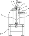
Fig. 1 is a schematic perspective view of an operating state of the embodiment.
Fig. 2 is a schematic perspective view of the first embodiment.
Fig. 3 is an enlarged view of a portion a in fig. 2.
Fig. 4 is a schematic cross-sectional structure diagram of the first embodiment.
Fig. 5 is a schematic view of the body structure of the support tube and push-pull rod engagement assembly.
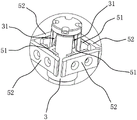
Fig. 6 is a schematic view of the body structure of the push-pull rod assembly.
Fig. 7 is an enlarged view of a portion B in fig. 6.
Fig. 8 is a schematic perspective view of the second embodiment.
Fig. 9 is an enlarged view of a portion C in fig. 8.
FIG. 10 is a schematic perspective view of a chuck according to a second embodiment.
FIG. 11 is a schematic view of a partial cross-sectional structure of a chuck in accordance with a second embodiment.
In the figure, 1, a machine base; 2. a jaw portion;
3. a push-pull rod; 31. a dovetail groove;
4. supporting a tube; 41. positioning pins;
5. a jacking block; 51. a slider; 52. a top plate;
6. a chuck; 61. a right-angle clamping groove; 62. a first clamping block; 621. a first inclined plane; 63. a second clamping block; 631. a second inclined plane; 64. a drive arm; 641. a guide shaft; 65. a pressure spring; 66. a yielding groove;
7. a lifting platform; 71. positioning the bolt;
8. a jacking table; 81. a telescopic arm; 82. a pressure head; 821. and (6) positioning a groove.
Detailed Description
The following are specific embodiments of the present invention and the accompanying drawings are used to further describe the technical solution of the present invention, but the present invention is not limited to these embodiments.
The first embodiment is as follows:
as shown in fig. 1-7, the pipe welding fixture comprises a base 1, a clamping jaw portion 2 for clamping the outer side wall of a vertical square pipe is arranged on the base 1, a push-pull rod 3 which vertically extends and can vertically move relative to the base 1 is further arranged on the base 1, a supporting pipe 4 for positioning and sleeving a square pipe is sleeved on the periphery of the push-pull rod 3, the lower end of the supporting pipe 4 is fixedly connected with the base 1, a plurality of dovetail grooves 31 which vertically extend in an inclined manner are formed in the outer peripheral surface of the push-pull rod 3, a supporting block 5 is slidably matched in the dovetail grooves 31, the outer end of the supporting block 5 penetrates through and extends out of the side wall of the supporting pipe 4, and when the push-pull rod 3 vertically moves, the supporting block 5 can be driven to outwards slide relative to the. When the square pipe is welded with the square pipe cover plate, the square pipe is vertically arranged on the base 1, the clamping jaw part 2 clamps the square pipe from outside to enable the square pipe to keep stable relative position with the square pipe cover plate, and then the welding gun device carries out accurate welding on the positioned square pipe and the square pipe cover plate to realize welding processing. By arranging the vertical push-pull rod 3 which can vertically move relative to the machine base 1 on the machine base 1, the push-pull rod 3 can be driven by a driving source such as a commercially available air cylinder, the supporting tube 4 is sleeved on the periphery of the push-pull rod 3, the supporting block 5 extending out of the supporting tube 4 is connected in a dovetail groove 31 arranged on the peripheral surface of the push-pull rod 3 in a sliding way, the supporting tube 4 can carry out primary positioning on the square tube, the square tube is prevented from being overturned by external force before being clamped, when the push-pull rod 3 is controlled to move vertically, the top support block 5 can gradually move outwards under the action of horizontal component force and the limiting action of the support tube 4, so that the top support block 5 can be propped against the inner side wall of the square tube, meanwhile, the square pipe welding fixture can be matched with the clamping jaw part 2 on the outer side to form positioning clamping from the opposite sides on the inner side and the outer side, stable and effective clamping positioning can be formed by controlling the stroke of the push-pull rod 3 aiming at the square pipes with different specifications and sizes, and the applicability of the welding fixture is improved. Further, the top support block 5 comprises a slide block 51 and a top plate 52, the slide block 51 is in sliding fit with the dovetail groove 31, one side of the top plate 52 is detachably connected with the slide block 51, and the other side of the top plate 52 can be attached to and abutted against the inner side wall of the square tube. Including slider 51 and roof 52 through setting up top braced block 5, and make roof 52 and slider 51 be for dismantling the cooperation, can choose for use the roof 52 assembly to slider 51 of corresponding size to the square pipe of different specification and dimension like this to guarantee location centre gripping effect, further improve the suitability. The clamping jaw part 2 comprises two clamping heads 6 which can horizontally move in opposite directions, the clamping heads 6 can be driven by a commercially available air cylinder, the right side surfaces of the two clamping heads 6 are respectively provided with a right-angle clamping groove 61, the inner side wall of each right-angle clamping groove 61 can be attached to the two adjacent side walls of the periphery of the square pipe, and the height position of each clamping head 6 corresponds to the height position of the supporting block 5. Include two just to and can follow the chuck 6 of horizontal direction relative motion through setting up clamping jaw part 2, and set up on chuck 6 can with the right angle complex right angle draw-in groove 61 of square pipe, the lateral wall of two right angle draw-in grooves 61 can be respectively with the four sides laminating supports of square pipe periphery after accomplishing the centre gripping like this, guarantee the centre gripping effect, the high position that sets up chuck 6 is corresponding with the high position of top kicking block 5, the clamping force of both sides can be used on same section of square pipe like this, it is higher to set up this section welded square tube cover board concentricity like this. Preferably, the bottom of the right-angle card slot 61 has a vertically extending relief slot 66. Through the groove 66 of stepping down that sets up vertical extension in the bottom of right angle draw-in groove 61, the groove 66 of stepping down can provide for the right angle edge of square pipe like this and steps down to improve the laminating effect of the inside wall of right angle draw-in groove 61 and the lateral wall of square pipe. The upper end surface of the support tube 4 has a positioning pin 41 for positioning the square tube cover plate. Through set up locating pin 41 at the upper end terminal surface of stay tube 4, set up the locating hole in welding the place ahead pipe cover plate center like this and can realize the spacing of square pipe cover plate with locating pin 41 cooperation to make the position of square pipe cover plate and square pipe relatively stable, guarantee the welding effect.
As shown in fig. 1, 2, and 4, the outer periphery of the support tube 4 is sleeved with a lifting platform 7 for supporting a square tube, the lifting platform 7 can slide up and down along the support tube 4, a radially extending positioning bolt 71 is screwed and inserted on the outer peripheral surface of the lifting platform 7, and the inner end of the positioning bolt 71 can be abutted against the outer sidewall of the support tube 4. By sleeving the lifting table 7 which can slide up and down on the periphery of the supporting tube 4, the lower end of the square tube can be supported on the lifting table 7, and the positioning bolt 71 is arranged on the outer peripheral surface of the lifting table 7, so that the welding operation can be realized at the most appropriate position by adjusting the position of the lifting table 7 for the square tubes with different lengths, and the applicability is further improved.
As shown in fig. 1, 2 and 4, a top pressing table 8 is arranged on the machine base 1, a telescopic arm 81 capable of moving along the vertical direction is arranged on the top pressing table 8, and a pressing head 82 capable of facing the support pipe 4 vertically is connected to the telescopic arm 81. Through set up roof pressure platform 8 on frame 1 to but set up vertical motion's flexible arm 81 on roof pressure platform 8, and connect the pressure head 82 that is just right with the stay tube 4 is vertical on flexible arm 81, like this when square tube cover plate installation back, pressure head 82 roof pressure makes its position stable to square tube cover plate surface when steerable flexible arm 81 moves down, thereby guarantees welding effect and suitability. Further, the lower end of the ram 82 is flared, and the lower end surface of the ram 82 has a positioning groove 821 for receiving the positioning pin 41. The lower extreme through setting up pressure head 82 is the loudspeaker form, can improve the pressure head 82 and square tube cover plate's effect scope, improves and compresses tightly the effect, sets up constant head tank 821 through the lower terminal surface at pressure head 82, can avoid locating pin 41 to interfere with pressure head 82 like this, guarantees to compress tightly the effect. The top pressing table 8 is connected with the machine base 1 in a sliding mode along the horizontal direction. Can slide along the horizontal direction on frame 1 through setting up top pressure platform 8, top pressure platform 8 accessible cylinders and other commercially available driving sources drive, like this when the welding completion back flexible arm 81 lifting short-distance earlier, then top pressure platform 8 can realize smooth and easy the unloading of square pipe at the certain distance of horizontal migration, avoids making overall structure not compact enough when unloading the design length overlength of flexible arm 81.
Example two:
as shown in fig. 8-11, this embodiment is substantially the same as the first embodiment, except that: the clamping jaw part 2 comprises two clamping heads 6 capable of moving horizontally and oppositely, each clamping head 6 comprises a first clamping block 62, a second clamping block 63 and a driving arm 64 capable of moving along the horizontal direction, a first inclined surface 621 is arranged on each first clamping block 62, a second inclined surface 631 is arranged on each second clamping block 63, each first clamping block 62 on any clamping head 6 is opposite to each second clamping block 63 on the other clamping head 6 along the moving direction, each first clamping block 62 is fixedly connected with the driving arm 64, a plurality of guide shafts 641 extending along the moving direction are fixedly connected onto the driving arm 64, each second clamping block 63 is connected with a plurality of guide shafts 641 in a sliding mode, a pressure spring 65 with two ends respectively abutting against the driving arm 64 and the corresponding second clamping block 63 is sleeved on the periphery of each guide shaft 641, and a right-angle clamping groove 61 can be formed between the first inclined surfaces 621 and the. For some square pipes with larger specification and size, the angle of the square pipe cannot be completely matched with the angle of the chuck 6 or the top support block 5 after the square pipe is sleeved on the periphery of the support pipe 4, and even an included angle close to 45 degrees can be formed, so that when the chuck 6 and the top support block 5 clamp the square pipe, the inner side wall and the outer side wall of the square pipe respectively form line contact with the chuck 6 and the top support block 5 under the influence of certain friction force, the clamping state of the whole square pipe is very unstable, and a welding gun is difficult to position; by arranging the chuck 6 to comprise the first clamping block 62, the second clamping block 63 and the driving arm 64 capable of moving along the horizontal direction, the first clamping block 62 is fixedly connected with the driving arm 64, the second clamping block 63 is connected with the driving arm 64 in a sliding way through the guide shaft 641, and the pressure spring 65 capable of controlling the position of the second clamping block 63 is sleeved on the periphery of the guide shaft 641, the first clamping block 62 and the second clamping block 63 on one chuck 6 are respectively opposite to the second clamping block 63 and the first clamping block 62 on the other chuck 6 along the horizontal direction, so that in the initial state, the second clamping block 63 can exceed a certain distance relative to the first clamping block 62 under the action of the pressure spring 65, even if the initial square pipe is placed at the angle, when the chuck 6 approaches towards the square pipe, the second inclined plane 631 on the second clamping block 63 can be firstly contacted with one edge of the square pipe, and the edge corresponding to the first inclined plane 621 on the square pipe is not contacted with the first inclined plane 621, so that the square pipe, compress in place at final pressure spring 65 and the laminating is kept away with the adjacent both sides of square pipe respectively to inclined plane one 621 and inclined plane two 631, and two clamp splice two 63 from both sides jointly to the square pipe effect, further ensure the smooth and easy rotation adjustment of square pipe to place the square pipe homoenergetic of initial placement and realize effectual centre gripping location to arbitrary angle, improve the suitability. Preferably, the first clamping block 62 and the second clamping block 63 are both heat-conducting material pieces.
The specific embodiments described herein are merely illustrative of the spirit of the invention. Various modifications, additions and substitutions for the specific embodiments described herein may be made by those skilled in the art without departing from the spirit of the invention or exceeding the scope of the invention as defined in the accompanying claims.
Claims (10)
1. A square tube welding fixture comprises a machine base (1), wherein a clamping jaw part (2) used for clamping the outer side wall of a vertical square tube is arranged on the machine base (1), it is characterized in that the machine base (1) is also provided with a push-pull rod (3) which extends vertically and can move vertically relative to the machine base (1), a supporting tube (4) for positioning and sleeving a square tube is sleeved on the periphery of the push-pull rod (3), the lower end of the supporting tube (4) is fixedly connected with the machine base (1), the peripheral surface of the push-pull rod (3) is provided with a plurality of dovetail grooves (31) which extend along the vertical direction in an inclined way, a plurality of jacking blocks (5) are arranged in the dovetail grooves (31) in a sliding way, the outer end of the supporting block (5) penetrates through and extends out of the side wall of the supporting tube (4), when the push-pull rod (3) moves vertically, the push-pull rod can drive the jacking block (5) to slide outwards relative to the supporting tube (4) along the horizontal direction and to be propped against the inner side wall of the corresponding square tube.
2. The square tube welding fixture according to claim 1, wherein the jacking block (5) comprises a sliding block (51) and a top plate (52), the sliding block (51) is in sliding fit with the dovetail groove (31), one side of the top plate (52) is detachably connected with the sliding block (51), and the other side of the top plate (52) can be abutted against the inner side wall of the square tube in an attaching manner.
3. The square pipe welding fixture according to claim 1 or 2, wherein the jaw part (2) comprises two chucks (6) capable of moving horizontally and oppositely, the opposite sides of the two chucks (6) are respectively provided with a right-angle clamping groove (61), the inner side wall of each right-angle clamping groove (61) can be attached to the two adjacent side walls of the periphery of the square pipe, and the height position of each chuck (6) corresponds to the height position of the supporting block (5).
4. The square pipe welding fixture according to claim 1 or 2, wherein the clamping jaw portion (2) comprises two clamping heads (6) capable of moving horizontally and oppositely, the clamping heads (6) comprise a first clamping block (62), a second clamping block (63) and a driving arm (64) capable of moving along a horizontal direction, the first clamping block (62) is provided with a first inclined surface (621), the second clamping block (63) is provided with a second inclined surface (631), the first clamping block (62) on any clamping head (6) is opposite to the second clamping block (63) on the other clamping head (6) along the moving direction of the clamping head (6), the first clamping block (62) is fixedly connected with the driving arm (64), the driving arm (64) is fixedly connected with a plurality of guide shafts (641) extending along the moving direction, the second clamping block (63) is slidably connected with the plurality of guide shafts (641), and a pressure spring (65) which is respectively abutted against the driving arm (64) and the second clamping block (63) is sleeved on the periphery of the guide shaft (641), when the square pipe is clamped, a right-angle clamping groove (61) used for being attached to two adjacent side walls of the periphery of the square pipe can be formed between the first inclined surface (621) and the second inclined surface (631).
5. The square tube welding jig according to claim 3, wherein the bottom of the right-angle clamping groove (61) is provided with a vertically extending relief groove (66).
6. The square pipe welding jig according to claim 1 or 2, wherein the upper end face of the support pipe (4) has a positioning pin (41) for positioning a square pipe cover plate.
7. The square pipe welding jig of claim 1 or 2, characterized in that the periphery of the supporting pipe (4) is sleeved with a lifting platform (7) for supporting the square pipe, the lifting platform (7) can slide up and down along the supporting pipe (4), the outer circumferential surface of the lifting platform (7) is screwed and inserted with a positioning bolt (71) extending along the radial direction, and the inner end of the positioning bolt (71) can be abutted against the outer side wall of the supporting pipe (4).
8. The square tube welding fixture according to claim 6, wherein the base (1) is provided with a top pressing table (8), the top pressing table (8) is provided with a telescopic arm (81) capable of moving vertically, and the telescopic arm (81) is connected with a pressure head (82) capable of vertically facing the support tube (4).
9. The square tube welding jig according to claim 8, wherein the lower end of the ram (82) is flared, and the lower end surface of the ram (82) is provided with a positioning groove (821) for receiving the positioning pin (41).
10. The square tube welding jig as claimed in claim 8, wherein the jacking platform (8) is connected with the machine base (1) in a sliding manner along a horizontal direction.
Priority Applications (1)
| Application Number | Priority Date | Filing Date | Title |
|---|---|---|---|
| CN201921230771.4U CN210281229U (en) | 2019-07-31 | 2019-07-31 | Square pipe welding fixture |
Applications Claiming Priority (1)
| Application Number | Priority Date | Filing Date | Title |
|---|---|---|---|
| CN201921230771.4U CN210281229U (en) | 2019-07-31 | 2019-07-31 | Square pipe welding fixture |
Publications (1)
| Publication Number | Publication Date |
|---|---|
| CN210281229U true CN210281229U (en) | 2020-04-10 |
Family
ID=70060832
Family Applications (1)
| Application Number | Title | Priority Date | Filing Date |
|---|---|---|---|
| CN201921230771.4U Active CN210281229U (en) | 2019-07-31 | 2019-07-31 | Square pipe welding fixture |
Country Status (1)
| Country | Link |
|---|---|
| CN (1) | CN210281229U (en) |
Cited By (1)
| Publication number | Priority date | Publication date | Assignee | Title |
|---|---|---|---|---|
| CN110280957A (en) * | 2019-07-31 | 2019-09-27 | 浙江钱江机器人有限公司 | A kind of square tubes soldering fixture |
-
2019
- 2019-07-31 CN CN201921230771.4U patent/CN210281229U/en active Active
Cited By (1)
| Publication number | Priority date | Publication date | Assignee | Title |
|---|---|---|---|---|
| CN110280957A (en) * | 2019-07-31 | 2019-09-27 | 浙江钱江机器人有限公司 | A kind of square tubes soldering fixture |
Similar Documents
| Publication | Publication Date | Title |
|---|---|---|
| CN109693069B (en) | Pipeline welding self-adaptation frock clamp | |
| CN202556085U (en) | Automatic centring clamp | |
| CN106312294B (en) | Frock clamp for water cooling motor housing straight seam welding and straight seam welding technique | |
| CN111922606B (en) | Welding tool of spray gun | |
| CN210232005U (en) | Double-side welding equipment for machining brake disc | |
| CN108057749A (en) | A kind of limiting device for the bending machine that can process a variety of calibers | |
| CN208196054U (en) | A kind of blower robot automatic welding work station | |
| CN210281229U (en) | Square pipe welding fixture | |
| CN207642515U (en) | A kind of pump housing laser welding rotation internal support device | |
| CN113334011B (en) | Furniture hardware corner welding forming fixing tool | |
| CN107363532A (en) | A kind of electrical box automatic assembling apparatus | |
| CN110280957A (en) | A kind of square tubes soldering fixture | |
| CN105127637A (en) | Automatic welding clamp for cross type iron tower workpiece | |
| CN219562036U (en) | Circumferential welding auxiliary overturning clamp | |
| CN208357986U (en) | A kind of motor stator argon welding machine | |
| CN108246903B (en) | Pipe expanding machining device and pipe expander with same | |
| CN113732613A (en) | Novel welding fixture and use method | |
| CN107378472A (en) | A kind of electrical box automatic assembly method | |
| CN220445538U (en) | Steel construction welding rotary worktable | |
| CN216858727U (en) | Elbow clamp and automatic welding machine | |
| CN106695288B (en) | For the automation equipment to eccentric shaft assembly bearing | |
| CN218284338U (en) | Welding tool for automobile instrument beam end plate | |
| CN215787895U (en) | Welding machining fixture tool | |
| CN112388163A (en) | Laser welding device | |
| CN220196726U (en) | Clamping tool for welding of welding ball |
Legal Events
| Date | Code | Title | Description |
|---|---|---|---|
| GR01 | Patent grant | ||
| GR01 | Patent grant |