CN210273461U - Wind-powered electricity generation lightning protection device convenient to installation and dismantlement - Google Patents
Wind-powered electricity generation lightning protection device convenient to installation and dismantlement Download PDFInfo
- Publication number
- CN210273461U CN210273461U CN201921341039.4U CN201921341039U CN210273461U CN 210273461 U CN210273461 U CN 210273461U CN 201921341039 U CN201921341039 U CN 201921341039U CN 210273461 U CN210273461 U CN 210273461U
- Authority
- CN
- China
- Prior art keywords
- threaded rod
- wind power
- plate
- protection device
- fixed
- Prior art date
- Legal status (The legal status is an assumption and is not a legal conclusion. Google has not performed a legal analysis and makes no representation as to the accuracy of the status listed.)
- Active
Links
Images


Abstract
The utility model belongs to the technical field of the lightning protection device, especially, be a wind-powered electricity generation lightning protection device convenient to installation and dismantlement, including wind-powered electricity generation lightning protection device main part, the both sides wall of wind-powered electricity generation lightning protection device main part all is fixed with first fixed plate and second fixed plate, the top of first fixed plate all is connected with the two-way threaded rod through the bearing rotation, the top that the top of two-way threaded rod all runs through corresponding second fixed plate is fixed with driven gear, the equal symmetrical cover in both ends lateral wall of two-way threaded rod is equipped with the connecting plate. The utility model discloses a set up first fixed plate, second fixed plate, two-way threaded rod, driven gear, connecting plate, montant, support column, roof, bull stick, carousel, driving gear, belt, inserted block and fixture block, can convenient and fast install wind-powered electricity generation lightning protection device main part on the bar-shaped piece, and dismantle also comparatively convenient and fast, so break down when wind-powered electricity generation lightning protection device main part, when needing to dismantle the maintenance or change, the efficiency of dismantlement and installation is higher.
Description
Technical Field
The utility model relates to a lightning protection device technical field specifically is a wind-powered electricity generation lightning protection device convenient to installation and dismantlement.
Background
Surge protector, also called lightning protection device, be one kind for various electronic equipment, instruments and meters, communication line provides safety protection's electronic device, when producing peak current or voltage suddenly because of external interference in electric return circuit or communication line, surge protector can switch on the reposition of redundant personnel in the time of the utmost point weak point, thereby avoid the surge to the harm of other equipment in the return circuit, in wind power generation equipment, all can set up the lightning protection device usually, the lightning protection device generally all is installed in the cabinet body, the lightning protection device is mostly through the fix with screw at present, break down when the lightning protection device breaks down, need dismantle to get off to maintain or when changing, it is comparatively troublesome to operate, therefore we have proposed a wind-powered electricity generation lightning protection device convenient to install and dismantle and solve above-mentioned problem.
SUMMERY OF THE UTILITY MODEL
Technical problem to be solved
The utility model provides a not enough to prior art, the utility model provides a wind-powered electricity generation lightning protection device convenient to installation and dismantlement has solved the problem that current lightning protection device for wind power generation equipment is not convenient for install and dismantle.
(II) technical scheme
In order to achieve the above object, the utility model provides a following technical scheme: a wind power lightning arrester convenient to mount and dismount comprises a wind power lightning arrester main body, wherein a first fixing plate and a second fixing plate are fixed on two side walls of the wind power lightning arrester main body, the top of the first fixing plate is connected with a bidirectional threaded rod in a rotating mode through a bearing, a driven gear is fixed at the top end of the bidirectional threaded rod penetrating through the top of the corresponding second fixing plate, connecting plates are symmetrically sleeved on the outer side walls of two ends of the bidirectional threaded rod, the bidirectional threaded rod is connected with the corresponding connecting plates through threads, vertical rods are arranged on the back of the bidirectional threaded rod, two ends of each vertical rod are fixedly connected with the top of the first fixing plate and the bottom of the second fixing plate respectively, the connecting plates are connected to the outer side walls of the corresponding vertical rods in a sliding mode, supporting columns are fixed on the top of the second fixing plate, and a, the top of the supporting column is fixedly connected with the bottom of the top plate, a rotating rod is arranged in the top plate in a penetrating way, the rotating rod is rotationally connected with the top plate through a bearing, the top of the rotating rod is fixed with a turntable, the bottom of the rotating rod is fixed with a driving gear, a belt is arranged below the top plate, the driving gear is in transmission connection with the two driven gears through the belt, the back of the wind power lightning protection device main body is provided with a bar-shaped block, the back of the bar-shaped block is fixed with a mounting plate, the front surface of the strip-shaped block is symmetrically provided with slots, the top and the bottom of the strip-shaped block are symmetrically provided with slots, the back of the wind power lightning protector main body is symmetrically fixed with inserting blocks, one side wall of the connecting plate close to the bar-shaped block is fixed with clamping blocks, the inserting blocks are respectively inserted into the corresponding slots, and the clamping blocks are respectively inserted into the corresponding clamping slots.
As a preferred technical scheme of the utility model, the one end that two-way threaded rod is close to driven gear all is connected through the top rotation of bearing and corresponding second fixed plate.
As a preferred technical scheme of the utility model, the screw thread opposite direction at two-way threaded rod both ends, set up the screw hole corresponding with two-way threaded rod screw thread respectively at the top of connecting plate, two-way threaded rod passes through threaded connection with the screw hole of corresponding connecting plate.
As an optimal technical scheme of the utility model, the slide opening has all been seted up at the top of connecting plate, the montant runs through the slide opening of corresponding connecting plate.
As an optimized technical scheme of the utility model, the surface of carousel is provided with anti-skidding line.
As an optimized technical scheme of the utility model, the screw hole has all been seted up in the front four corners of mounting panel.
(III) advantageous effects
Compared with the prior art, the utility model provides a wind-powered electricity generation lightning protection device convenient to installation and dismantlement possesses following beneficial effect:
this wind-powered electricity generation lightning protection device convenient to installation and dismantlement, through setting up first fixed plate, the second fixed plate, two-way threaded rod, driven gear, the connecting plate, the montant, the support column, the roof, the bull stick, the carousel, the driving gear, the belt, inserted block and fixture block, can convenient and fast install wind-powered electricity generation lightning protection device main part on the bar-shaped piece, and dismantle also comparatively convenient and fast, so break down when wind-powered electricity generation lightning protection device main part, need dismantle when getting off the maintenance or change, the efficiency of dismantlement and installation is higher.
Drawings
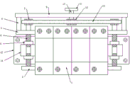
FIG. 1 is a schematic view of the overall structure of the present invention;
FIG. 2 is a schematic view of the left side structure of the whole body of the present invention;
FIG. 3 is a schematic view of the structure of the bar block of the present invention;
fig. 4 is a schematic view of the insert block structure of the present invention.
In the figure: 1. a wind power lightning protection device main body; 2. a first fixing plate; 3. a second fixing plate; 4. a bidirectional threaded rod; 5. a driven gear; 6. a connecting plate; 7. a vertical rod; 8. a support pillar; 9. a top plate; 10. a rotating rod; 11. a turntable; 12. a driving gear; 13. a belt; 14. a bar-shaped block; 15. mounting a plate; 16. a slot; 17. a card slot; 18. inserting a block; 19. a clamping block; 20. and (4) a slide hole.
Detailed Description
The technical solutions in the embodiments of the present invention will be described clearly and completely with reference to the accompanying drawings in the embodiments of the present invention, and it is obvious that the described embodiments are only some embodiments of the present invention, not all embodiments. Based on the embodiments in the present invention, all other embodiments obtained by a person skilled in the art without creative work belong to the protection scope of the present invention.
Examples
Referring to fig. 1-4, the present invention provides the following technical solutions: a wind power lightning arrester convenient to mount and dismount comprises a wind power lightning arrester main body 1, a first fixing plate 2 and a second fixing plate 3 are fixed on two side walls of the wind power lightning arrester main body 1, the top of the first fixing plate 2 is connected with a bidirectional threaded rod 4 through a bearing in a rotating manner, a driven gear 5 is fixed on the top of the bidirectional threaded rod 4 penetrating through the top of the corresponding second fixing plate 3, connecting plates 6 are symmetrically sleeved on the outer side walls of two ends of the bidirectional threaded rod 4, the bidirectional threaded rod 4 is connected with the corresponding connecting plates 6 through threads, vertical rods 7 are arranged on the back of the bidirectional threaded rod 4, two ends of each vertical rod 7 are fixedly connected with the top of the first fixing plate 2 and the bottom of the corresponding second fixing plate 3 respectively, the connecting plates 6 are connected with the outer side walls of the corresponding vertical rods 7 in a sliding manner, supporting columns 8 are fixed on the top of the second, the top of the supporting column 8 is fixedly connected with the bottom of the top plate 9, a rotating rod 10 is arranged in the top plate 9 in a penetrating way, the rotating rod 10 is rotatably connected with the top plate 9 through a bearing, the top of the rotating rod 10 is fixedly provided with a rotating disc 11, the bottom of the rotating rod 10 is fixedly provided with a driving gear 12, a belt 13 is arranged below the top plate 9, the driving gear 12 is in transmission connection with the two driven gears 5 through the belt 13, the back of the wind power lightning arrester main body 1 is provided with a strip-shaped block 14, the back of the strip-shaped block 14 is fixedly provided with a mounting plate 15, slots 16 are symmetrically formed in the front of the strip-shaped block 14, slots 17 are symmetrically formed in the top and the bottom of the strip-shaped block 14, an inserting block 18 is symmetrically fixed on the back of the wind power lightning arrester main body 1, one side wall of the connecting plate 6, which is close to the strip-shaped block 14, the inserting blocks 18 are respectively inserted into the corresponding.
In this embodiment, through setting up first fixed plate 2, second fixed plate 3, two-way threaded rod 4, driven gear 5, connecting plate 6, montant 7, support column 8, roof 9, bull stick 10, carousel 11, driving gear 12, belt 13, inserted block 18 and fixture block 19, can convenient and fast install wind-powered electricity generation lightning protection device main part 1 on bar-shaped piece 14, and dismantle also comparatively convenient and fast, so break down when wind-powered electricity generation lightning protection device main part 1, need dismantle when getting off maintenance or change, the efficiency of dismantlement and installation is higher.
Specifically, one end of the bidirectional threaded rod 4 close to the driven gear 5 is rotatably connected with the top of the corresponding second fixing plate 3 through a bearing.
In this embodiment, the end of the bidirectional threaded rod 4 close to the driven gear 5 is rotatably connected with the top of the corresponding second fixing plate 3 through a bearing, so that the bidirectional threaded rod 4 is more stable when rotating.
Specifically, the two ends of the bidirectional threaded rod 4 are opposite in thread direction, the top of the connecting plate 6 is respectively provided with a threaded hole corresponding to the threads of the bidirectional threaded rod 4, and the bidirectional threaded rod 4 is in threaded connection with the threaded hole of the corresponding connecting plate 6.
In this embodiment, the two ends of the bidirectional threaded rod 4 have opposite screw directions, and the top of the connecting plate 6 is provided with a threaded hole corresponding to the screw of the bidirectional threaded rod 4, so as to be matched with the bidirectional threaded rod 4, so that when the bidirectional threaded rod 4 rotates, the connecting plate 6 can be driven to move correspondingly.
Specifically, the top of the connecting plate 6 is provided with a sliding hole 20, and the vertical rod 7 penetrates through the sliding hole 20 of the corresponding connecting plate 6.
In this embodiment, the top of the connecting plate 6 is provided with a sliding hole 20 so that the vertical rod 7 can smoothly penetrate through the corresponding connecting plate 6, and the connecting plate 6 can slide along with the rotation of the bidirectional threaded rod 4.
Specifically, the surface of the turntable 11 is provided with anti-skid lines.
In this embodiment, the anti-slip lines are arranged on the surface of the turntable 11 to play a role of anti-slip, so that people can rotate the turntable 11 conveniently.
Specifically, four corners of the front surface of the mounting plate 15 are all provided with screw holes.
In this embodiment, the four corners of the front surface of the mounting plate 15 are provided with screw holes, so that the mounting plate 15 can be easily fixed in the cabinet.
The utility model discloses a theory of operation and use flow: the mounting plate 15 is fixed in the cabinet body through screws, when the wind power lightning arrester main body 1 breaks down and needs to be disassembled, the rotary plate 11 can be rotated, the rotary plate 11 drives the rotary rod 10 to rotate, the rotary rod 10 drives the driving gear 12 to rotate, the driving gear 12 drives the two driven gears 5 to rotate through the belt 13, the driven gears 5 drive the corresponding two-way threaded rods 4 to rotate, the two-way threaded rods 4 drive the corresponding connecting plates 6 to move away from the bar-shaped blocks 14, so that the clamping blocks 19 can be separated from the clamping grooves 17 of the bar-shaped blocks 14, the wind power lightning arrester main body 1 can be disassembled from the bar-shaped blocks 14, when the wind power lightning arrester main body is installed, the inserting blocks 18 on the wind power lightning arrester main body 1 are inserted into the corresponding inserting grooves 16 of the bar-shaped blocks 14, so that the clamping blocks 19 can be just positioned in the direction of the clamping, therefore, the wind power lightning protector main body 1 can be fixed on the bar-shaped blocks 14.
Finally, it should be noted that: although the present invention has been described in detail with reference to the foregoing embodiments, it will be apparent to those skilled in the art that modifications may be made to the embodiments described in the foregoing embodiments, or equivalents may be substituted for elements thereof. Any modification, equivalent replacement, or improvement made within the spirit and principle of the present invention should be included in the protection scope of the present invention.
Claims (6)
1. The utility model provides a wind-powered electricity generation lightning protection device convenient to installation and dismantlement, includes wind-powered electricity generation lightning protection device main part (1), its characterized in that: the wind power lightning arrester comprises a wind power lightning arrester main body (1), wherein a first fixing plate (2) and a second fixing plate (3) are fixed on two side walls of the wind power lightning arrester main body (1), the top of the first fixing plate (2) is connected with a bidirectional threaded rod (4) through a bearing in a rotating manner, the top of the bidirectional threaded rod (4) penetrates through the top of the corresponding second fixing plate (3) and is fixed with a driven gear (5), the outer side walls of two ends of the bidirectional threaded rod (4) are symmetrically sleeved with connecting plates (6), the bidirectional threaded rod (4) is in threaded connection with the corresponding connecting plates (6), vertical rods (7) are arranged on the back of the bidirectional threaded rod (4), two ends of each vertical rod (7) are fixedly connected with the top of the first fixing plate (2) and the bottom of the corresponding second fixing plate (3) respectively, and the connecting plates (, the top of the second fixing plate (3) is fixed with a supporting column (8), a top plate (9) is arranged above the wind power lightning protector main body (1), the top of the supporting column (8) is fixedly connected with the bottom of the top plate (9), a rotating rod (10) penetrates through the top plate (9), the rotating rod (10) is rotatably connected with the top plate (9) through a bearing, a rotating disc (11) is fixed at the top of the rotating rod (10), a driving gear (12) is fixed at the bottom of the rotating rod (10), a belt (13) is arranged below the top plate (9), the driving gear (12) is in transmission connection with two driven gears (5) through the belt (13), a strip-shaped block (14) is arranged on the back of the wind power lightning protector main body (1), a mounting plate (15) is fixed on the back of the strip-shaped block (14), and slots (16) are symmetrically formed in the front of the strip-shaped block (14), clamping grooves (17) are symmetrically formed in the top and the bottom of the strip-shaped block (14), inserting blocks (18) are symmetrically fixed to the back of the wind power lightning protector main body (1), clamping blocks (19) are fixed to one side wall, close to the strip-shaped block (14), of the connecting plate (6), the inserting blocks (18) are respectively inserted into the corresponding inserting grooves (16), and the clamping blocks (19) are respectively inserted into the corresponding clamping grooves (17).
2. The wind power lightning protector convenient to mount and dismount as claimed in claim 1, wherein: and one end of the bidirectional threaded rod (4) close to the driven gear (5) is rotatably connected with the top of the corresponding second fixing plate (3) through a bearing.
3. The wind power lightning protector convenient to mount and dismount as claimed in claim 1, wherein: the thread directions of two ends of the bidirectional threaded rod (4) are opposite, the top of the connecting plate (6) is respectively provided with a threaded hole corresponding to the thread of the bidirectional threaded rod (4), and the bidirectional threaded rod (4) is in threaded connection with the threaded hole of the corresponding connecting plate (6).
4. The wind power lightning protector convenient to mount and dismount as claimed in claim 1, wherein: slide holes (20) are formed in the tops of the connecting plates (6), and the vertical rods (7) penetrate through the slide holes (20) of the corresponding connecting plates (6).
5. The wind power lightning protector convenient to mount and dismount as claimed in claim 1, wherein: the surface of the rotary table (11) is provided with anti-skid lines.
6. The wind power lightning protector convenient to mount and dismount as claimed in claim 1, wherein: screw holes are formed in four corners of the front face of the mounting plate (15).
Priority Applications (1)
| Application Number | Priority Date | Filing Date | Title |
|---|---|---|---|
| CN201921341039.4U CN210273461U (en) | 2019-08-19 | 2019-08-19 | Wind-powered electricity generation lightning protection device convenient to installation and dismantlement |
Applications Claiming Priority (1)
| Application Number | Priority Date | Filing Date | Title |
|---|---|---|---|
| CN201921341039.4U CN210273461U (en) | 2019-08-19 | 2019-08-19 | Wind-powered electricity generation lightning protection device convenient to installation and dismantlement |
Publications (1)
| Publication Number | Publication Date |
|---|---|
| CN210273461U true CN210273461U (en) | 2020-04-07 |
Family
ID=70017550
Family Applications (1)
| Application Number | Title | Priority Date | Filing Date |
|---|---|---|---|
| CN201921341039.4U Active CN210273461U (en) | 2019-08-19 | 2019-08-19 | Wind-powered electricity generation lightning protection device convenient to installation and dismantlement |
Country Status (1)
| Country | Link |
|---|---|
| CN (1) | CN210273461U (en) |
Cited By (1)
| Publication number | Priority date | Publication date | Assignee | Title |
|---|---|---|---|---|
| CN112909881A (en) * | 2021-01-26 | 2021-06-04 | 芜湖市凯鑫避雷器有限责任公司 | Mounting base of lightning arrester |
-
2019
- 2019-08-19 CN CN201921341039.4U patent/CN210273461U/en active Active
Cited By (2)
| Publication number | Priority date | Publication date | Assignee | Title |
|---|---|---|---|---|
| CN112909881A (en) * | 2021-01-26 | 2021-06-04 | 芜湖市凯鑫避雷器有限责任公司 | Mounting base of lightning arrester |
| CN112909881B (en) * | 2021-01-26 | 2022-03-22 | 芜湖市凯鑫避雷器有限责任公司 | Mounting base of lightning arrester |
Similar Documents
| Publication | Publication Date | Title |
|---|---|---|
| CN210273461U (en) | Wind-powered electricity generation lightning protection device convenient to installation and dismantlement | |
| CN111917014B (en) | Wall-mounted outdoor protection power distribution cabinet | |
| CN210865395U (en) | Electronic information display stand with good protection effect | |
| CN208782317U (en) | A kind of emergency lighting distribution box facilitating installation | |
| CN212809622U (en) | Intelligent display screen | |
| CN211208915U (en) | Power distribution cabinet with adjustable body width | |
| CN211295908U (en) | Low-voltage draw-out type switch cabinet | |
| CN211547456U (en) | Rotatable traffic management sign | |
| CN210861021U (en) | Connector lug protection device of wall washer | |
| CN213520704U (en) | Lightning protection mounting rack for mounting LED electronic screen | |
| CN212719068U (en) | Visual talkback display screen | |
| CN214589919U (en) | Novel power distribution cabinet | |
| CN216253498U (en) | Current protection device for current monitor | |
| CN214852140U (en) | Capacitor protection measurement and control device | |
| CN214204477U (en) | Extensible distribution automation terminal | |
| CN219937715U (en) | Intelligent building management device | |
| CN211266033U (en) | High-low pressure complete equipment cabinet structure | |
| CN213520756U (en) | Rainproof device for outdoor building electrical power distribution cabinet | |
| CN216958952U (en) | Direct current screen with dehumidification function | |
| CN214124317U (en) | Lightning rod for lightning protection engineering | |
| CN219436420U (en) | External high-safety electric power cabinet | |
| CN216214988U (en) | Movable high-low voltage cabinet with electric shock prevention structure | |
| CN216624928U (en) | Intelligent power lighting power distribution cabinet convenient to disassemble and maintain | |
| CN216010510U (en) | Auxiliary device for spunbonded nonwoven production line | |
| CN218418997U (en) | Wall show shelf |
Legal Events
| Date | Code | Title | Description |
|---|---|---|---|
| GR01 | Patent grant | ||
| GR01 | Patent grant |