CN210262319U - Textile fabric drying and forming device - Google Patents
Textile fabric drying and forming device Download PDFInfo
- Publication number
- CN210262319U CN210262319U CN201921037469.7U CN201921037469U CN210262319U CN 210262319 U CN210262319 U CN 210262319U CN 201921037469 U CN201921037469 U CN 201921037469U CN 210262319 U CN210262319 U CN 210262319U
- Authority
- CN
- China
- Prior art keywords
- cloth
- support
- fixedly connected
- roller
- forming device
- Prior art date
- Legal status (The legal status is an assumption and is not a legal conclusion. Google has not performed a legal analysis and makes no representation as to the accuracy of the status listed.)
- Expired - Fee Related
Links
Images


Abstract
The utility model relates to a textile fabric drying and forming device, which comprises a first support and a second support, wherein the first support is rotatably connected with a cloth placing roller, the second support is connected with a cloth rolling roller, a drying box is arranged between the first support and the second support, the bottom of the inner cavity of the drying box is fixedly connected with a supporting leg, an air heater is arranged between the supporting legs, the air heater is connected with an air duct, the top of the supporting leg is fixedly connected with a dewatering plate, two sides of the dewatering plate are fixedly connected with a protection plate, the top of the dewatering plate is provided with a diversion groove, the utility model discloses a cloth is placed on the cloth placing roller by the dewatering roller and the dewatering plate, one end of the cloth is wound on the cloth rolling roller, the cloth passes through the drying box, the cloth is dewatered and leveled by the dewatering roller, and the cloth is dried by an air jet on the protection plate, the cloth drying and ironing machine is simple to operate, can effectively dry and iron cloth, and improves the quality of products.
Description
Technical Field
The utility model relates to a textile fabric drying and forming device belongs to textile fabric stoving technical field.
Background
At present, the textile industry in China has been rapidly developed in recent years, and the development of textile equipment is followed, as is well known, common textile fabrics are cleaned before use, and are dried after cleaning, the existing fabric drying is generally to simply blow the fabrics dry, and a measure for shaping the fabrics is lacked, so that the processing method is easy to cause the fabrics to have wrinkles and deformation in the drying process, the appearance of the fabrics is influenced, the subsequent processing is not facilitated, the product grade is reduced, the fabric drying speed is low, and the finished product efficiency is low.
SUMMERY OF THE UTILITY MODEL
The utility model aims to provide a textile fabric drying and forming device, through being equipped with dehydration board and dehydration roller, put the cloth on the cloth roller, the one end of cloth twines on the cloth roller, the cloth passes through the stoving case, start first motor, drive the lead screw rotation, make the slider on the lead screw do the axial motion on the lead screw, start electric telescopic handle, electric telescopic handle stretches out and draws back and drives the dehydration roller and laminate cloth and dehydration board, through the removal of slider, make the dehydration roller dewater the flattening to the cloth, be equipped with the electrical heating roller in the dehydration roller, can accelerate the drying of cloth, while dewater the flattening through the dehydration roller to the cloth, start the air heater, in the guard plate of introducing hot air into dehydration board both sides through the air duct, be equipped with the jet orifice on the guard plate, aim at the cloth with steam and blow dry, be equipped with the guiding gutter on the dehydration board, when the dehydration roller dewaters the cloth, cloth discharged moisture is discharged through the mouth of a river down along the guiding gutter, and the top of stoving case is equipped with gas vent and air discharge fan, with the vapor escape of stoving incasement, reduces the humidity of stoving incasement for the stoving speed of cloth, easy operation can effectually dry and iron the cloth, improves the quality and the drying efficiency of product, in order to solve the problem that proposes among the above-mentioned background art.
In order to achieve the above object, the utility model provides a following technical scheme:
a textile fabric drying and forming device comprises a first support and a second support, wherein a cloth laying roller is rotatably connected to the first support, a cloth rolling roller is connected to the second support, a drying box is arranged between the first support and the second support, supporting legs are fixedly connected to the bottom of an inner cavity of the drying box, a hot air blower is arranged between the supporting legs, an air guide pipe is connected to the hot air blower, a dewatering plate is fixedly connected to the top of each supporting leg, protection plates are fixedly connected to two sides of the dewatering plate, a flow guide groove is formed in the top of the dewatering plate, a water outlet is formed in the right side of the flow guide groove, first motors are symmetrically arranged on the left side and the right side of the top end of the drying box, a lead screw is connected to each first motor, a slide block is connected to each lead screw in a threaded manner, an electric telescopic rod is fixedly connected to the bottom of each slide block, the improved drying oven is characterized in that a connecting plate is arranged in the pressure reducing shell, a pressure reducing spring is fixedly connected between the connecting plate and the top of the inner cavity of the pressure reducing shell, a connecting rod is fixedly connected to the bottom of the connecting plate, a dewatering roller is rotatably connected to the connecting rod, an electric heating roller is arranged in the dewatering roller, an exhaust port is formed in the top of the drying oven, and an exhaust fan is arranged above the exhaust port.
Furthermore, the two sides of the cloth feeding roller are rotatably connected with bearings, and the bearings are fixedly connected to the first support.
Furthermore, one side fixedly connected with motor backup pad of second support, the last fixedly connected with second motor of motor backup pad, the second support is passed to the one end of cloth roller and second motor fixed connection, the other end of cloth roller passes through the bearing and connects on the second support.
Further, evenly be provided with the air jet on the guard plate, the bottom of guard plate is connected with the air inlet, the air inlet all through connection with every air jet, the air duct of air heater is connected on the air inlet.
Furthermore, a cloth inlet and a cloth outlet are formed in two sides of the drying box, and heat insulation cloth is connected to the cloth inlet and the cloth outlet.
Further, the outside of stoving case is equipped with the insulating layer, the right side of stoving case is equipped with the delivery port, pass through the pipe connection between delivery port and the lower mouth of a river.
Furthermore, a guide rod is arranged above the first motor, a through hole corresponding to the guide rod is formed in the upper end of the sliding block, and the guide rod penetrates through the through hole of the sliding block and is fixedly connected to the two sides of the drying box.
Further, the middle position of the top of the inner cavity of the drying box is fixedly connected with a mounting plate, a limiting nut is arranged on the mounting plate, and the screw rods are connected with the limiting nut.
The utility model has the advantages that: the utility model relates to a textile fabric drying and forming device, through being equipped with dehydration board and dehydration roller, put the cloth on the cloth roller, the one end of cloth twines on the cloth roller, the cloth passes through the stoving case, start first motor, drive the lead screw rotation, make the slider on the lead screw be axial motion on the lead screw, start electric telescopic handle, electric telescopic handle stretches out and draws back the dehydration roller and laminate cloth and dehydration board, through the removal of slider, make the dehydration roller dewater the flattening to the cloth, be equipped with the electrical heating roller in the dehydration roller, can accelerate the drying of cloth, while dewater the flattening through the dehydration roller to the cloth, start the air heater, in the guard plate of introducing hot air into dehydration board both sides through the air duct, be equipped with the jet orifice on the guard plate, aim at the cloth with steam and dry, be equipped with the guiding gutter on the dehydration board, when the dehydration roller dewaters the cloth, cloth discharged moisture is discharged through the mouth of a river down along the guiding gutter, and the top of stoving case is equipped with gas vent and air discharge fan, with the vapor escape of stoving incasement, reduces the humidity of stoving incasement for the stoving speed of cloth, easy operation can effectually dry and iron the cloth, improves the quality and the drying efficiency of product.
Drawings
The accompanying drawings are included to provide a further understanding of the invention, and are incorporated in and constitute a part of this specification, illustrate embodiments of the invention, and together with the description serve to explain the invention and not to limit the invention.
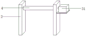
Fig. 1 is a schematic view of the overall structure of a textile fabric drying and forming device of the present invention;
FIG. 2 is a schematic view of a fixed dewatering roll of the drying and forming device for textile fabric of the present invention;
FIG. 3 is a top view of a dewatering plate of the drying and forming device for textile fabric of the present invention;
FIG. 4 is a schematic view of a protective plate of the drying and forming device for textile fabric of the present invention;
fig. 5 is a top view of a connection structure between a first motor and a slider of the drying and forming device for textile fabric of the present invention;
fig. 6 is a schematic structural view of a second support of the textile fabric drying and forming device of the present invention;
reference numbers in the figures: 1. a first bracket; 2. a second bracket; 3. a cloth releasing roller; 4. a cloth roller; 5. a drying box; 6. supporting legs; 7. a hot air blower; 8. an air duct; 9. a dewatering plate; 10. a protection plate; 11. a diversion trench; 12. a water outlet; 13. a first motor; 14. a screw rod; 15. a slider; 16. an electric telescopic rod; 17. a pressure reducing housing; 18. a connecting plate; 19. a relief spring; 20. a connecting rod; 21. a dewatering roll; 22. an electrically heated roller; 23. an exhaust port; 24. an exhaust fan; 25. an air jet; 26. an air inlet; 27. a water outlet; 28. a guide bar; 29. mounting a plate; 30. a limit nut; 31. a second motor.
Detailed Description
The preferred embodiments of the present invention will be described in conjunction with the accompanying drawings, and it will be understood that they are presented herein only to illustrate and explain the present invention, and not to limit the present invention.
Referring to fig. 1-6, the present invention provides a technical solution:
a textile fabric drying and forming device comprises a first support 1 and a second support 2, a cloth releasing roller 3 is rotatably connected to the first support 1, a cloth rolling roller 4 is connected to the second support 2, a drying box 5 is arranged between the first support 1 and the second support 2, cloth is placed on the cloth releasing roller 3, one end of the cloth is wound on the cloth rolling roller 4, a second motor 31 is started to drive the cloth rolling roller 4 to rotate, so that the cloth passes through the drying box 5, supporting legs 6 are fixedly connected to the bottom of an inner cavity of the drying box 5, a hot air blower 7 is arranged between the supporting legs 6, an air guide pipe 8 is connected to the hot air blower 7, a dewatering plate 9 is fixedly connected to the top of each supporting leg 6, protection plates 10 are fixedly connected to two sides of the dewatering plate 9, a diversion trench 11 is formed in the top of the dewatering plate 9, a water drainage port 12 is formed in the right side of the diversion trench 11, when the dewatering roll 21 dewaters the cloth, water discharged by the cloth is discharged through the lower water gap 12 along the diversion trench 11, the first motor 13 is symmetrically arranged on the left side and the right side of the top end of the drying box 5, the first motor 13 is connected with the screw rod 14, the screw rod 14 is in threaded connection with the slide block 15, the first motor 13 is started to drive the screw rod 14 to rotate, so that the slide block 15 on the screw rod 14 axially moves on the screw rod 14, the bottom of the slide block 15 is fixedly connected with the electric telescopic rod 16, the bottom of the electric telescopic rod 16 is fixedly connected with the decompression shell 17, the decompression shell 17 is internally provided with the connecting plate 18, the decompression spring 19 is fixedly connected between the connecting plate 18 and the top of the inner cavity of the decompression shell 17, the bottom of the connecting plate 18 is fixedly connected with the connecting rod 20, the dewatering roll 21 is rotatably, 16 flexible drive dewatering roller 21 of electric telescopic handle is laminated cloth and dewatering plate 9, through the removal of slider 15 for dewatering roller 21 dewaters the flattening to the cloth, when electric telescopic handle 16 drove dewatering roller 21 and moves down, connecting rod 20 of dewatering roller 21 both sides drives connecting plate 18 and shifts up, makes the decompression spring 19 compression in the decompression casing 17, alleviates dewatering roller 21 to the direct pressure of dewatering plate 9, makes things convenient for dewatering roller 21 to laminate on the surface of dewatering plate 9, be equipped with electrical heating roller 22 in the dewatering roller 21, can accelerate the stoving of cloth, gas vent 23 has been seted up at the top of stoving case 5, the top of gas vent 23 is equipped with air discharge fan 24, discharges the vapor in stoving case 5, reduces the humidity in the stoving case 5 for the stoving speed of cloth.
More specifically, the two sides of the cloth feeding roller 3 are rotatably connected with bearings, the bearings are fixedly connected on the first support 1, the cloth feeding roller 3 is conveniently rotated, one side of the second support 2 is fixedly connected with a motor support plate, the motor support plate is fixedly connected with a second motor 31, one end of the cloth feeding roller 4 passes through the second support 2 and is fixedly connected with the second motor 31, the other end of the cloth feeding roller 4 is connected on the second support 2 through the bearings, the second motor 31 is started to drive the cloth feeding roller 4 to rotate, the protection plate 10 is uniformly provided with air nozzles 25, the bottom of the protection plate 10 is connected with air inlets 26, the air inlets 26 are communicated with each air nozzle 25, the air duct 8 of the air heater 7 is connected with the air inlets 26, when the cloth is dehydrated and leveled through the dehydrating roller 21, hot air is introduced into the protection plates 10 at the two sides of the dehydrating plate 9 through the air duct 8, an air jet 25 is arranged on the protection plate 10, hot air is blown and dried by aiming at the cloth, a cloth inlet and a cloth outlet are arranged on two sides of the drying box 5, heat insulation cloth is connected to the cloth inlet and the cloth outlet to prevent heat from overflowing, a heat insulation layer is arranged on the outer side of the drying box 5 to keep the temperature in the drying box 5, a water outlet 27 is arranged on the right side of the drying box 5, the water outlet 27 is connected with the water outlet 12 through a pipeline to discharge redundant water in the drying box 5, so that the drying efficiency is prevented from being influenced by overlarge humidity in the drying box 5, a guide rod 28 is arranged above the first motor 13, a through hole corresponding to the guide rod 28 is arranged at the upper end of the slide block 15, the guide rod 28 penetrates through holes of the slide block 15 to be fixedly connected to two sides of the drying box 5, the slide block 15 moves along the screw rod 14 to prevent the slide block 15 from rotating relatively through the guide rod 28, cause the equipment to damage, the inner chamber top intermediate position fixedly connected with mounting panel 29 of stoving case 5, be equipped with stop nut 30 on the mounting panel 29, lead screw 14 all is connected with stop nut 30, makes things convenient for lead screw 14 to rotate.
The utility model discloses the theory of operation: when the drying and forming device is used, cloth is placed on the cloth placing roller 3, one end of the cloth is wound on the cloth rolling roller 4, the cloth passes through the drying box 5, the first motor 13 is started to drive the screw rod 14 to rotate, so that the slide block 15 on the screw rod 14 moves axially on the screw rod 14, the electric telescopic rod 16 is started, the electric telescopic rod 16 stretches and retracts to drive the dewatering roller 21 to attach the cloth to the dewatering plate 9, the dewatering roller 21 dewaters and levels the cloth through the movement of the slide block 15, when the electric telescopic rod 16 drives the dewatering roller 21 to move downwards, the connecting rods 20 on two sides of the dewatering roller 21 drive the connecting plates 18 to move upwards, so that the pressure reducing springs 19 in the pressure reducing shell 17 compress to reduce the direct pressure of the dewatering plate 9 by the dewatering roller 21, the dewatering roller 21 is convenient to attach to the surface of the dewatering plate 9, and the hot air heater 7 is started when the cloth is dewatered and, in the guard plate 10 of 9 both sides of hot-blast introduction dehydration board through air duct 8, be equipped with air jet 25 on the guard plate 10, aim at the cloth with steam and dry, be equipped with guiding gutter 11 on the dehydration board 9, when dehydration roller 21 dewaters the cloth, cloth exhaust moisture is discharged through lower mouth of a river 12 along guiding gutter 11, the top of stoving case 5 is equipped with gas vent 23 and air discharge fan 24, discharge the vapor in the stoving case 5, reduce the humidity in the stoving case 5, accelerate the stoving speed of cloth.
The above is the preferred embodiment of the present invention, and the technical personnel in the field of the present invention can also change and modify the above embodiment, therefore, the present invention is not limited to the above specific embodiment, and any obvious improvement, replacement or modification made by the technical personnel in the field on the basis of the present invention all belong to the protection scope of the present invention.
Claims (8)
1. The utility model provides a textile fabric stoving forming device, includes first support (1) and second support (2), its characterized in that: the cloth unwinding device is characterized in that a cloth unwinding roller (3) is rotatably connected to the first support (1), a cloth winding roller (4) is connected to the second support (2), a drying box (5) is arranged between the first support (1) and the second support (2), supporting legs (6) are fixedly connected to the bottom of an inner cavity of the drying box (5), an air heater (7) is arranged between the supporting legs (6), an air duct (8) is connected to the air heater (7), a dewatering plate (9) is fixedly connected to the top of each supporting leg (6), protection plates (10) are fixedly connected to two sides of the dewatering plate (9), a diversion trench (11) is formed in the top of the dewatering plate (9), a water drainage port (12) is formed in the right side of the diversion trench (11), first motors (13) are symmetrically arranged on the left side and the right side of the top end of the drying box (5), and a screw rod (14) is connected to each first motor, threaded connection has slider (15) on lead screw (14), the bottom fixedly connected with electric telescopic handle (16) of slider (15), the bottom fixedly connected with decompression casing (17) of electric telescopic handle (16), be equipped with connecting plate (18) in decompression casing (17), fixedly connected with decompression spring (19) between connecting plate (18) and decompression casing (17) inner chamber top, the bottom fixedly connected with connecting rod (20) of connecting plate (18), it is connected with dewatering roll (21) to rotate on connecting rod (20), be equipped with electrical heating roller (22) in dewatering roll (21), gas vent (23) have been seted up at the top of stoving case (5), the top of gas vent (23) is equipped with air discharge fan (24).
2. The textile fabric drying and forming device according to claim 1, characterized in that: the two sides of the cloth releasing roller (3) are rotatably connected with bearings, and the bearings are fixedly connected to the first support (1).
3. The textile fabric drying and forming device according to claim 1, characterized in that: one side fixedly connected with motor support board of second support (2), fixedly connected with second motor (31) in the motor support board, second support (2) and second motor (31) fixed connection are passed to the one end of cloth roller (4), the other end of cloth roller (4) passes through the bearing and connects on second support (2).
4. The textile fabric drying and forming device according to claim 1, characterized in that: evenly be provided with air jet (25) on guard plate (10), the bottom of guard plate (10) is connected with air inlet (26), air inlet (26) and every air jet (25) all through connection, air duct (8) of air heater (7) are connected on air inlet (26).
5. The textile fabric drying and forming device according to claim 1, characterized in that: and a cloth inlet and a cloth outlet are formed in two sides of the drying box (5), and heat-insulating cloth is connected to the cloth inlet and the cloth outlet.
6. The textile fabric drying and forming device according to claim 1, characterized in that: the outside of stoving case (5) is equipped with the insulating layer, the right side of stoving case (5) is equipped with delivery port (27), pass through the pipe connection between delivery port (27) and lower mouth of a river (12).
7. The textile fabric drying and forming device according to claim 1, characterized in that: a guide rod (28) is arranged above the first motor (13), a through hole corresponding to the guide rod (28) is formed in the upper end of the sliding block (15), and the guide rod (28) penetrates through the through hole of the sliding block (15) and is fixedly connected to the two sides of the drying box (5).
8. The textile fabric drying and forming device according to claim 1, characterized in that: the inner chamber top intermediate position fixedly connected with mounting panel (29) of stoving case (5), be equipped with stop nut (30) on mounting panel (29), lead screw (14) all are connected with stop nut (30).
Priority Applications (1)
| Application Number | Priority Date | Filing Date | Title |
|---|---|---|---|
| CN201921037469.7U CN210262319U (en) | 2019-07-04 | 2019-07-04 | Textile fabric drying and forming device |
Applications Claiming Priority (1)
| Application Number | Priority Date | Filing Date | Title |
|---|---|---|---|
| CN201921037469.7U CN210262319U (en) | 2019-07-04 | 2019-07-04 | Textile fabric drying and forming device |
Publications (1)
| Publication Number | Publication Date |
|---|---|
| CN210262319U true CN210262319U (en) | 2020-04-07 |
Family
ID=70047105
Family Applications (1)
| Application Number | Title | Priority Date | Filing Date |
|---|---|---|---|
| CN201921037469.7U Expired - Fee Related CN210262319U (en) | 2019-07-04 | 2019-07-04 | Textile fabric drying and forming device |
Country Status (1)
| Country | Link |
|---|---|
| CN (1) | CN210262319U (en) |
Cited By (6)
| Publication number | Priority date | Publication date | Assignee | Title |
|---|---|---|---|---|
| CN111472124A (en) * | 2020-04-17 | 2020-07-31 | 海宁市富连机械有限公司 | Dewatering device of composite shading cloth |
| CN111664690A (en) * | 2020-06-12 | 2020-09-15 | 诸暨市众创机械设备厂 | Textile oven |
| CN111719268A (en) * | 2020-06-30 | 2020-09-29 | 黄远明 | Drying and shaping system and drying and shaping process for yarn after printing and dyeing |
| CN111895737A (en) * | 2020-07-27 | 2020-11-06 | 谢招兰 | Rolling type drying device for cloth processing |
| CN112393569A (en) * | 2020-11-09 | 2021-02-23 | 梁伟滨 | Preliminary dewatering device is used in washing of textile fabric |
| CN114541066A (en) * | 2022-02-15 | 2022-05-27 | 广德正欣经编有限公司 | Quick drying equipment and method for producing and processing bleached and dyed knitwear |
-
2019
- 2019-07-04 CN CN201921037469.7U patent/CN210262319U/en not_active Expired - Fee Related
Cited By (9)
| Publication number | Priority date | Publication date | Assignee | Title |
|---|---|---|---|---|
| CN111472124A (en) * | 2020-04-17 | 2020-07-31 | 海宁市富连机械有限公司 | Dewatering device of composite shading cloth |
| CN111664690A (en) * | 2020-06-12 | 2020-09-15 | 诸暨市众创机械设备厂 | Textile oven |
| CN111719268A (en) * | 2020-06-30 | 2020-09-29 | 黄远明 | Drying and shaping system and drying and shaping process for yarn after printing and dyeing |
| CN111895737A (en) * | 2020-07-27 | 2020-11-06 | 谢招兰 | Rolling type drying device for cloth processing |
| CN111895737B (en) * | 2020-07-27 | 2022-07-05 | 浙江赐源纺织有限公司 | Rolling type drying device for cloth processing |
| CN112393569A (en) * | 2020-11-09 | 2021-02-23 | 梁伟滨 | Preliminary dewatering device is used in washing of textile fabric |
| CN112393569B (en) * | 2020-11-09 | 2022-09-27 | 桐乡市法赛欧服饰有限公司 | Preliminary dewatering device is used in washing of textile fabric |
| CN114541066A (en) * | 2022-02-15 | 2022-05-27 | 广德正欣经编有限公司 | Quick drying equipment and method for producing and processing bleached and dyed knitwear |
| CN114541066B (en) * | 2022-02-15 | 2024-03-15 | 广德正欣经编有限公司 | Quick-drying equipment and quick-drying method for production and processing of bleaching and dyeing knitwear |
Similar Documents
| Publication | Publication Date | Title |
|---|---|---|
| CN210262319U (en) | Textile fabric drying and forming device | |
| CN209853414U (en) | Textile fabric winding device with ironing function | |
| CN208668063U (en) | The shaping and drying device of jacquard fabric | |
| CN109160345B (en) | Gauze stoving rolling equipment | |
| CN209326274U (en) | A kind of drying unit for textile fabric | |
| CN213328284U (en) | Textile steam setting machine | |
| CN205636348U (en) | Paper machine quick drying device | |
| CN213328249U (en) | Textile fabric dehumidification flattening device | |
| CN111442628A (en) | Woven fabric dewatering and drying device for textile printing and dyeing and use method thereof | |
| CN212158020U (en) | Industrial drying furnace with efficient drying function | |
| CN211689537U (en) | Mechanical processing equipment for chemical raw materials to be dehydrated | |
| CN210946124U (en) | Ironing machine is used in processing of classic skirt | |
| CN210394836U (en) | Dewatering equipment for textile fabrics | |
| CN211340024U (en) | Drying and sterilizing equipment for printing and dyeing machining | |
| CN209306683U (en) | A kind of textile machines weaving materials guiding device | |
| CN114608292B (en) | Quick air-drying equipment for fiber textile materials | |
| CN215593426U (en) | Drying device is used in bedspread production | |
| CN211665372U (en) | Ironing and drying device for assembly line textile fabric | |
| CN208533036U (en) | A kind of water-jet loom dewatering drying device | |
| CN212097907U (en) | Production system of solvent-free insulating composite material | |
| CN209955508U (en) | Anti-adhesion knitted fabric printing device | |
| CN209944943U (en) | Cloth weaving cotton thread drying device | |
| CN209307715U (en) | A kind of dress ornament ironing forming machine | |
| CN113123049A (en) | Mechanical processing equipment for chemical raw materials to be dehydrated | |
| CN212227629U (en) | Drying device is used in production of medical gauze |
Legal Events
| Date | Code | Title | Description |
|---|---|---|---|
| GR01 | Patent grant | ||
| GR01 | Patent grant | ||
| CF01 | Termination of patent right due to non-payment of annual fee | ||
| CF01 | Termination of patent right due to non-payment of annual fee |
Granted publication date: 20200407 |