CN210251696U - Automatic control dust collecting equipment - Google Patents
Automatic control dust collecting equipment Download PDFInfo
- Publication number
- CN210251696U CN210251696U CN201920525743.9U CN201920525743U CN210251696U CN 210251696 U CN210251696 U CN 210251696U CN 201920525743 U CN201920525743 U CN 201920525743U CN 210251696 U CN210251696 U CN 210251696U
- Authority
- CN
- China
- Prior art keywords
- dust
- collecting pipe
- ash collecting
- electrostatic adsorption
- drying layer
- Prior art date
- Legal status (The legal status is an assumption and is not a legal conclusion. Google has not performed a legal analysis and makes no representation as to the accuracy of the status listed.)
- Active
Links
Images
Abstract
The utility model discloses an automatic control dust collecting equipment, including the main part, locate the top case of main part upper end and locate the ash collecting pipe of main part below, the both sides of main part are the air-supply line respectively and go out the tuber pipe, the inside of main part has set gradually filter screen, drying layer and electrostatic absorption net along the wind direction, the filter screen with be the condensation chamber between the drying layer, the drying layer with be the ionization chamber between the electrostatic absorption net, the lower extreme of air-supply line, condensation chamber and ionization chamber all with the ash collecting pipe intercommunication. The utility model can realize automatic control in the dust removal process by arranging the controller, does not need manual adjustment, and improves the dust removal efficiency; the multi-stage filtration design is adopted, and the flue gas dust is subjected to coarse filtration, humidification and condensation and electrostatic adsorption in sequence, so that the dust removal and filtration effects are greatly improved; set up dust collection pipe and water pump simultaneously, can clear up the dust that gathers in time effectively, do not hinder equipment normal operating.
Description
Technical Field
The utility model relates to a dust collecting equipment field, concretely relates to automatic control dust collecting equipment.
Background
In the production and processing process of a factory, a large amount of dust is generated, the working environment and the health of workers are seriously affected, and therefore, dust removing equipment needs to be installed in the factory to collect and treat the smoke dust. The existing dust removing equipment generally needs manual regulation and control, single-stage filtration is mostly adopted for dust removal, the dust removing effect cannot be guaranteed, and meanwhile, collected dust cannot be timely and effectively cleaned, so that the normal operation of the equipment is influenced.
SUMMERY OF THE UTILITY MODEL
In view of the above shortcoming of prior art, the utility model aims to provide an automatic control dust collecting equipment for need manual operation among the solution prior art, dust removal effect is not good, the problem that the dust of gathering can not in time be cleared up.
In order to achieve the above and other related purposes, the utility model provides an automatic control dust removing device, which comprises a main body, a top box arranged at the upper end of the main body and an ash collecting pipe arranged below the main body, wherein an air inlet pipe and an air outlet pipe are respectively arranged at the two sides of the main body, a filter screen, a drying layer and an electrostatic adsorption net are sequentially arranged in the main body along the wind direction, a condensation chamber is arranged between the filter screen and the drying layer, an ionization chamber is arranged between the drying layer and the electrostatic adsorption net, and the lower ends of the air inlet pipe, the condensation chamber and the ionization chamber are all communicated with the ash collecting pipe;
a water tank, a power supply and a controller are sequentially arranged in the top box; a dust monitor and a spray head are installed at the top of the condensation chamber, the spray head is communicated with the water tank, and a first electromagnetic valve is installed on a communication pipeline; a first pressure sensor is arranged on the electrostatic adsorption net; one side of the ash collecting pipe is provided with a water pump, the water outlet end of the water pump is connected with a flushing head in the ash collecting pipe, a second electromagnetic valve is arranged on a connecting pipeline, and the bottom of the ash collecting pipe is provided with a second pressure sensor.
Preferably, the power supply is electrically connected to the controller.
Preferably, the controller is electrically connected to the first solenoid valve, the second solenoid valve, the first pressure sensor and the second pressure sensor.
Preferably, a dust scraping plate is arranged on the electrostatic adsorption net and moves up and down along the electrostatic adsorption net.
Preferably, one end of the ash collecting pipe, which is far away from the water pump, is connected with a sewage draining outlet.
Compared with the prior art, the beneficial effects of the utility model are that: automatic control in the dust removal process can be realized by arranging the controller, manual adjustment is not needed, and the dust removal efficiency is improved; the multi-stage filtration design is adopted, and the flue gas dust is subjected to coarse filtration, humidification and condensation and electrostatic adsorption in sequence, so that the dust removal and filtration effects are greatly improved; set up dust collection pipe and water pump simultaneously, can clear up the dust that gathers in time effectively, do not hinder equipment normal operating.
Drawings
The present invention will be described in further detail with reference to the accompanying drawings and specific embodiments.
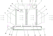
Fig. 1 is a schematic structural diagram of an automatic control dust removing device provided by the utility model.
Wherein the reference numerals are specified as follows: the device comprises a main body 1, a top box 2, an ash collecting pipe 3, an air inlet pipe 4, an air outlet pipe 5, a filter screen 6, a drying layer 7, an electrostatic adsorption net 8, a condensation chamber 9, an ionization chamber 10, a water tank 11, a power supply 12, a controller 13, a dust monitor 14, a spray header 15, a first electromagnetic valve 16, a first pressure sensor 17, a water pump 18, a flushing header 19, a second electromagnetic valve 20, a second pressure sensor 21, a dust scraping plate 22 and a sewage outlet 23.
Detailed Description
As shown in fig. 1, the utility model provides an automatic control dust removing device, which comprises a main body 1, a top box 2 arranged at the upper end of the main body 1 and an ash collecting pipe 3 arranged below the main body 1, wherein an air inlet pipe 4 and an air outlet pipe 5 are respectively arranged at two sides of the main body 1, a filter screen 6, a drying layer 7 and an electrostatic adsorption net 8 are sequentially arranged in the main body 1 along the wind direction, a condensation chamber 9 is arranged between the filter screen 6 and the drying layer 7, an ionization chamber 10 is arranged between the drying layer 7 and the electrostatic adsorption net 8, and the lower ends of the air inlet pipe 4, the condensation chamber 9 and the ionization chamber 10 are all communicated with the ash collecting pipe 3;
the top box 2 is internally provided with a water tank 11, a power supply 12 and a controller 13 in sequence; a dust monitor 14 and a spray head 15 are arranged at the top in the condensation chamber 9, the spray head 15 is communicated with the water tank 11, and a first electromagnetic valve 16 is arranged on a communication pipeline; the electrostatic adsorption net 8 is provided with a first pressure sensor 17; one side of the dust collecting pipe 3 is provided with a water pump 18, the water outlet end of the water pump 18 is connected with a flushing head 19 in the dust collecting pipe 3, a second electromagnetic valve 20 is arranged on the connecting pipeline, and the bottom of the dust collecting pipe 3 is provided with a second pressure sensor 21.
Wherein, the power source 12 is electrically connected with the controller 13; the controller 13 is electrically connected with the first electromagnetic valve 16, the second electromagnetic valve 20, the first pressure sensor 17 and the second pressure sensor 21; the electrostatic adsorption net 8 is provided with a dust scraping plate 22, and the dust scraping plate 22 moves up and down along the electrostatic adsorption net 8; one end of the ash collecting pipe 3 far away from the water pump 18 is connected with a sewage draining outlet 23.
When the dust collecting device is used, gas with dust enters the device from the air inlet pipe 4, the dust with larger particles directly falls into the dust collecting pipe 3 after being screened by the filter screen 6, after the gas enters the condensation chamber 9, the dust monitor 16 detects the dust content in the gas, the controller 13 controls the closing of the first electromagnetic valve 16 according to the detection result to start humidifying and condensing the gas, the dust is condensed into clusters and flows into the dust collecting pipe 3 along with water, the humidified gas enters the ionization chamber 10 after passing through the drying layer 7, the dust with smaller particles is adsorbed on the electrostatic adsorption net 8, meanwhile, the first pressure sensor 17 transmits the detection signal to the controller, when the pressure reaches a preset value, the controller 13 controls the dust scraping plate 22 to move up and down to remove the adsorbed dust, the dust falls into the dust collecting pipe 3, and when the dust amount in the dust collecting pipe 3 exceeds the preset pressure value of the second pressure sensor 21, the controller 13 controls the second electromagnetic valve 20 to be opened, the water pump 18 starts to flush the interior of the dust collecting pipe 3 through the flushing head 19, the waste water is discharged from the sewage outlet 23, and the gas after the three-stage filtration is discharged from the air outlet pipe 5, so that the whole working process of automatically controlling the dust removal is completed.
The above, only be the concrete implementation of the preferred embodiment of the present invention, but the protection scope of the present invention is not limited thereto, and any person skilled in the art is in the technical scope of the present invention, according to the technical solution of the present invention and the utility model, the concept of which is equivalent to replace or change, should be covered within the protection scope of the present invention.
Claims (5)
1. The automatic control dust removing equipment is characterized by comprising a main body (1), a top box (2) arranged at the upper end of the main body (1) and an ash collecting pipe (3) arranged below the main body (1), wherein an air inlet pipe (4) and an air outlet pipe (5) are respectively arranged on two sides of the main body (1), a filter screen (6), a drying layer (7) and an electrostatic adsorption net (8) are sequentially arranged in the main body (1) along the wind direction, a condensation chamber (9) is arranged between the filter screen (6) and the drying layer (7), an ionization chamber (10) is arranged between the drying layer (7) and the electrostatic adsorption net (8), and the lower ends of the air inlet pipe (4), the condensation chamber (9) and the ionization chamber (10) are communicated with the ash collecting pipe (3);
a water tank (11), a power supply (12) and a controller (13) are sequentially arranged in the top box (2); a dust monitor (14) and a spray head (15) are installed at the top in the condensation chamber (9), the spray head (15) is communicated with the water tank (11), and a first electromagnetic valve (16) is installed on a communication pipeline; a first pressure sensor (17) is arranged on the electrostatic adsorption net (8); one side of the ash collecting pipe (3) is provided with a water pump (18), the water outlet end of the water pump (18) is connected with a flushing head (19) in the ash collecting pipe (3) and a second electromagnetic valve (20) is arranged on a connecting pipeline, and the bottom of the ash collecting pipe (3) is provided with a second pressure sensor (21).
2. An automatically controlled dust-removing apparatus according to claim 1, characterized in that: the power supply (12) is electrically connected with the controller (13).
3. An automatically controlled dust-removing apparatus according to claim 2, characterized in that: the controller (13) is electrically connected with the first electromagnetic valve (16), the second electromagnetic valve (20), the first pressure sensor (17) and the second pressure sensor (21).
4. An automatically controlled dust-removing apparatus according to claim 1, characterized in that: and a dust scraping plate (22) is arranged on the electrostatic adsorption net (8), and the dust scraping plate (22) moves up and down along the electrostatic adsorption net (8).
5. An automatically controlled dust-removing apparatus according to claim 1, characterized in that: one end of the ash collecting pipe (3) far away from the water pump (18) is connected with a sewage draining outlet (23).
Priority Applications (1)
| Application Number | Priority Date | Filing Date | Title |
|---|---|---|---|
| CN201920525743.9U CN210251696U (en) | 2019-04-17 | 2019-04-17 | Automatic control dust collecting equipment |
Applications Claiming Priority (1)
| Application Number | Priority Date | Filing Date | Title |
|---|---|---|---|
| CN201920525743.9U CN210251696U (en) | 2019-04-17 | 2019-04-17 | Automatic control dust collecting equipment |
Publications (1)
| Publication Number | Publication Date |
|---|---|
| CN210251696U true CN210251696U (en) | 2020-04-07 |
Family
ID=70022645
Family Applications (1)
| Application Number | Title | Priority Date | Filing Date |
|---|---|---|---|
| CN201920525743.9U Active CN210251696U (en) | 2019-04-17 | 2019-04-17 | Automatic control dust collecting equipment |
Country Status (1)
| Country | Link |
|---|---|
| CN (1) | CN210251696U (en) |
Cited By (1)
| Publication number | Priority date | Publication date | Assignee | Title |
|---|---|---|---|---|
| CN115447099A (en) * | 2022-11-10 | 2022-12-09 | 深圳市科佳保温隔热板有限公司 | Dust anti-deformation filtering equipment for production of specified polystyrene extruded sheet |
-
2019
- 2019-04-17 CN CN201920525743.9U patent/CN210251696U/en active Active
Cited By (1)
| Publication number | Priority date | Publication date | Assignee | Title |
|---|---|---|---|---|
| CN115447099A (en) * | 2022-11-10 | 2022-12-09 | 深圳市科佳保温隔热板有限公司 | Dust anti-deformation filtering equipment for production of specified polystyrene extruded sheet |
Similar Documents
| Publication | Publication Date | Title |
|---|---|---|
| CN210171054U (en) | Automatic environment purifying device | |
| CN206045707U (en) | A kind of intelligent electric automatization dust arrester | |
| CN105617798A (en) | Air-conveying type ultrasonic wave micron-grade dry fog dust suppression system and method | |
| CN205461614U (en) | Waste gas dust collecting equipment | |
| CN108525410B (en) | Device and method for collecting dust mist | |
| CN210251696U (en) | Automatic control dust collecting equipment | |
| CN205913912U (en) | Bag -type dust collector | |
| CN208794689U (en) | A kind of air filtration cleaning device of green building | |
| CN216092762U (en) | Novel high-efficient dust remover | |
| CN215822691U (en) | Dehumidification ash removal gas cleaning device | |
| CN201551960U (en) | Wet-type desulphurization duster | |
| CN213965575U (en) | Coke oven loss smoke and dust distributing type dust pelletizing system | |
| CN210171077U (en) | Water film dust remover | |
| CN208450171U (en) | A kind of spraying waste gas recovery utilizes system | |
| CN113769523A (en) | Environment-friendly energy-saving dust remover | |
| CN208124470U (en) | A kind of detachable multifunctional cleaning device | |
| CN206184603U (en) | Electrostatic waste incinerator exhaust gas purifying apparatus | |
| CN109751647A (en) | The kitchen ventilator of automatic cleaning electrostatic precipitation unit | |
| CN111085074A (en) | Gas dust removal purification device | |
| CN205412541U (en) | Air -assisted ultrasonic wave micron order dry fog presses down dirt system | |
| CN220177726U (en) | Ash removal room of cement plant | |
| CN220677108U (en) | Dust removing device | |
| CN110026027A (en) | A kind of deduster filtering cylinder ash cleaning device | |
| CN220386153U (en) | Bag-type dust remover for purifying waste gas | |
| CN209954482U (en) | Efficient and energy-saving dry-type grinding dust treatment equipment |
Legal Events
| Date | Code | Title | Description |
|---|---|---|---|
| GR01 | Patent grant | ||
| GR01 | Patent grant |