CN210209980U - Special positioning device convenient for cutter machining - Google Patents
Special positioning device convenient for cutter machining Download PDFInfo
- Publication number
- CN210209980U CN210209980U CN201920745362.1U CN201920745362U CN210209980U CN 210209980 U CN210209980 U CN 210209980U CN 201920745362 U CN201920745362 U CN 201920745362U CN 210209980 U CN210209980 U CN 210209980U
- Authority
- CN
- China
- Prior art keywords
- plate
- rod
- vertical
- diaphragm
- fixed
- Prior art date
- Legal status (The legal status is an assumption and is not a legal conclusion. Google has not performed a legal analysis and makes no representation as to the accuracy of the status listed.)
- Expired - Fee Related
Links
Images


Abstract
The utility model discloses a be convenient for special positioner of cutter processing, including bottom suspension fagging and riser, the top of bottom suspension fagging is fixed with the riser, and the top of riser is fixed with last backup pad to the internally mounted of riser has the worm, the upper and lower both sides of worm all mesh and are connected with the worm wheel, and the inside of worm wheel is fixed with the connecting rod, and the diaphragm is installed in the outside of connecting rod, the right-hand member of diaphragm is inside to be connected with the dead lever through torsion spring. This be convenient for special positioner of cutter processing is provided with the diaphragm, it rotates to drive the diaphragm through the rotation of connecting rod for 2 diaphragms drive 2 stripper plates and rotate to the position of the horizontal central line of riser, thereby make 2 stripper plate interact extrude the location to the cutter, the stripper plate can constitute rotatoryly with the diaphragm through dead lever and montant simultaneously, and then the stripper plate of being convenient for fixes a position fixedly to the inclined plane of cutter, improves whole positioner's stability.
Description
Technical Field
The utility model relates to a cutter processing technology field specifically is a special positioner of cutter processing of being convenient for.
Background
The cutter refers to the used blade that is used for cutting or polishes in our life or machinery field, cutter in the life generally is the rectangle form, and the last cutter that uses of mechanical equipment has rectangle form and circular form, need polish the processing into the inclined plane with the upper and lower two sides of one end when processing the cutter of rectangle form, make the fine cutting work that carries on of one end of cutter, consequently need use special positioner when cutter processing, although the special positioner's of cutter on the market is various at present the variety, but still have some weak points, for example:
1. the traditional positioning device in the market can only clamp and position a horizontal plane or a vertical plane, and when the inclined plane of the cutter is machined, the traditional positioning device cannot clamp and fix the surface of the inclined plane of the cutter, so that the stability of clamping and fixing is reduced;
2. generally add man-hour to the rectangle cutter, will incline to polish to the face of the upper and lower surface of rectangle cutter one end for the one end of cutter is isosceles triangle, the use in the cutter later stage of being convenient for, but traditional positioner only has the centre gripping locate function, can not prescribe a limit to the scope that the inclined plane was polished, and inconvenient staff carries out the processing work.
Therefore, the positioning device special for cutter processing is provided, and the problems can be well solved.
SUMMERY OF THE UTILITY MODEL
An object of the utility model is to provide a be convenient for special positioner of cutter processing to solve the special positioner of traditional cutter processing on the existing market that above-mentioned background art provided and can not carry out the centre gripping to the inclined plane surface of cutter fixed, can not carry out the problem of injecing to the scope that the inclined plane was polished.
In order to achieve the above object, the utility model provides a following technical scheme: a special positioning device convenient for cutter processing comprises a lower supporting plate and a vertical plate, wherein the vertical plate is fixed above the lower supporting plate, an upper supporting plate is fixed at the top of the vertical plate, a worm is arranged in the vertical plate, worm wheels are meshed and connected with the upper side and the lower side of the worm, a connecting rod is fixed in the worm wheels, and the outside of the connecting rod is provided with a transverse plate, the inside of the right end of the transverse plate is connected with a fixed rod through a torsion spring, the outside of the fixed rod is provided with a vertical rod, and the bottom end of the vertical rod is fixed with an extrusion plate, the inner side surface of the extrusion plate is bonded with a friction protection pad, and a bidirectional screw rod is arranged in the extrusion plate, and the outer side of the bidirectional screw rod is connected with an installation block, the left end movable shaft of the installation block is connected with a supporting rod, and the left end loose axle of bracing piece is connected with the locating plate, the medial surface of riser is fixed with places the board.
Preferably, the connection mode of diaphragm and connecting rod is the welding, and the medial surface of diaphragm and the horizontal central line of connecting rod are not on same straight line to the diaphragm is provided with 2, and 2 rotation directions of diaphragm are opposite simultaneously.
Preferably, the fixed rod and the vertical rod are of an integrated structure, the fixed rod and the vertical rod are in a vertical state, the front end of the fixed rod is connected with the transverse plate through a bearing, and meanwhile, the rear end of the fixed rod forms a rotating structure with the transverse plate through a torsion spring.
Preferably, the left side of the extrusion plate is open, the open length of the left side of the extrusion plate is greater than that of the positioning plate, and the positioning plate and the extrusion plate form a sliding structure through the support rod.
Preferably, the length of the supporting rod is less than one half of the length of the positioning plate, 2 groups of the supporting rods are arranged, and 2 supporting rods are arranged in each group.
Preferably, the highest point of the placing plate is lower than the transverse center line of the vertical plate, and the length of the placing plate is smaller than that of the lower supporting plate.
Compared with the prior art, the beneficial effects of the utility model are that: the special positioning device for facilitating the processing of the cutter;
(1) the transverse plates are driven to rotate through the rotation of the connecting rods, so that 2 transverse plates drive 2 extrusion plates to rotate to the position of the transverse center line of the vertical plate, the 2 extrusion plates interact to extrude and position the cutter, meanwhile, the extrusion plates can rotate with the transverse plates through the fixing rods and the vertical rods, the extrusion plates can position and fix the inclined surfaces of the cutter conveniently, and the stability of the whole positioning device is improved;
(2) be fixed with the locating plate, the rotation through two-way lead screw drives 2 installation pieces of outside threaded connection and moves to the inboard simultaneously for the installation piece drives the bracing piece and promotes the locating plate and move, and then the locating plate of being convenient for fixes a position the processing range on inclined plane, so that the fine processing range on definite inclined plane.
Drawings
FIG. 1 is a schematic view of the overall main sectional structure of the present invention;
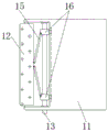
FIG. 2 is a right side view of the structure of the present invention;
FIG. 3 is a schematic view of a cross-sectional view of the squeeze plate according to the present invention;
fig. 4 is an enlarged schematic structural view of a portion a in fig. 1 according to the present invention.
In the figure: 1. a lower support plate; 2. a vertical plate; 3. a worm; 4. a connecting rod; 5. a worm gear; 6. an upper support plate; 7. a transverse plate; 8. fixing the rod; 9. a vertical rod; 10. a torsion spring; 11. a pressing plate; 12. positioning a plate; 13. a bidirectional screw rod; 14. a friction protection pad; 15. a support bar; 16. mounting blocks; 17. placing the plate.
Detailed Description
The technical solutions in the embodiments of the present invention will be described clearly and completely with reference to the accompanying drawings in the embodiments of the present invention, and it is obvious that the described embodiments are only some embodiments of the present invention, not all embodiments. Based on the embodiments in the present invention, all other embodiments obtained by a person skilled in the art without creative work belong to the protection scope of the present invention.
Referring to fig. 1-4, the present invention provides a technical solution: a special positioning device convenient for cutter processing comprises a lower support plate 1, a vertical plate 2, a worm 3, a connecting rod 4, a worm wheel 5, an upper support plate 6, a transverse plate 7, a fixed rod 8, a vertical rod 9, a torsion spring 10, an extrusion plate 11, a positioning plate 12, a bidirectional screw 13, a friction protection pad 14, a support rod 15, a mounting block 16 and a placing plate 17, wherein the vertical plate 2 is fixed above the lower support plate 1, the upper support plate 6 is fixed on the top of the vertical plate 2, the worm 3 is installed inside the vertical plate 2, the worm wheel 5 is connected on the upper side and the lower side of the worm 3 in a meshing manner, the connecting rod 4 is fixed inside the worm wheel 5, the transverse plate 7 is installed on the outer side of the connecting rod 4, the right end inside of the transverse plate 7 is connected with the fixed rod 8 through the torsion spring 10, the vertical rod 9 is installed on the outer side of the fixed rod 8, the, a bidirectional screw rod 13 is arranged in the extrusion plate 11, an installation block 16 is connected to the outer side of the bidirectional screw rod 13, a support rod 15 is connected to a left end movable shaft of the installation block 16, a positioning plate 12 is connected to the left end movable shaft of the support rod 15, and a placing plate 17 is fixed to the inner side surface of the vertical plate 2;
the transverse plates 7 and the connecting rods 4 are connected in a welding mode, the inner side surfaces of the transverse plates 7 and the transverse center line of the connecting rods 4 are not on the same straight line, 2 transverse plates 7 are arranged, and the rotating directions of the 2 transverse plates 7 are opposite, so that the transverse plates 7 well drive the extrusion plates 11 to lift, and the extrusion plates 11 can extrude and fix the cutters;
the fixing rod 8 and the vertical rod 9 are of an integrated structure, the fixing rod 8 and the vertical rod 9 are in a vertical state, the front end of the fixing rod 8 is connected with the transverse plate 7 in a bearing mode, and meanwhile, the rear end of the fixing rod 8 and the transverse plate 7 form a rotating structure through the torsion spring 10, so that the fixing rod 8 and the vertical rod 9 drive the extrusion plate 11 to rotate;
the left side of the extrusion plate 11 is open, the length of the opening on the left side of the extrusion plate 11 is greater than that of the positioning plate 12, and the positioning plate 12 and the extrusion plate 11 form a sliding structure through the supporting rod 15, so that the positioning plate 12 and the supporting rod 15 are placed in the opening on the left side of the extrusion plate 11;
the length of the supporting rods 15 is less than one half of the length of the positioning plate 12, and 2 groups of 2 supporting rods 15 are arranged, so that the position of the positioning plate 12 can be conveniently adjusted through the movement of the supporting rods 15, and the range of the processing surface can be conveniently determined by the positioning plate 12;
the highest point of placing board 17 is less than the horizontal central line of riser 2, and the length of placing board 17 is less than the length of bottom suspension fagging 1, and then is convenient for place board 17 and places the one end of cutter to the cutter is fixed a position tightly to the cutter in the later stage.
The working principle is as follows: when the positioning device special for facilitating the cutter processing is used, firstly, the whole device is moved into a working area, the lower support plate 1 is fixed on an external processing device through an external tool after the positioning device reaches the working area, then as shown in the attached drawing 1-2, one end of a rectangular cutter to be processed is placed on the placing plate 17, then, the worm 3 is manually rotated, the worm 3 drives the 2 worm wheels 5 on the upper side and the lower side to reversely rotate at the same time in the rotating process, the 2 worm wheels 5 drive the connecting rod 4 inside to rotate when rotating, so that the connecting rod 4 drives the transverse plate 7 on the outer side to rotate, the transverse plate 7 drives the extrusion plate 11 to descend when rotating, when the friction protection pad 14 made of rubber material on the inner side surface of the extrusion plate 11 is in contact with the inclined surface of the cutter, at the moment, as shown in the attached drawing 1 and the attached drawing 4, the extrusion plate 11 rotates with the transverse plate 7 through the fixed rod 8 and the, the extrusion plate 11 can extrude and fix the horizontal plane of the cutter and can extrude and fix the inclined plane of the cutter, the stability of the positioning device special for processing the whole cutter is improved, and the extrusion plate 11 can be driven to reset at the later stage of force storage through the torsion spring 10 so as to be convenient for the later use of the extrusion plate 11;
when the range of the processing surface of the tool needs to be located, at this time, as shown in fig. 1 and fig. 3, the bidirectional screw rod 13 is manually rotated, the bidirectional screw rod 13 drives the 2 mounting blocks 16, which are in threaded connection with the outer side, to simultaneously move inwards when rotating, so that the 2 mounting blocks 16 drive the supporting rod 15 to eject the positioning plate 12, thereby adjusting the position of the positioning plate 12, so that the range of the processing surface is determined by the positioning plate 12, the displacement of the 2 positioning plates 12 moving when the number of rotations of the bidirectional screw rod 13 comes is the same, and then the tool can be processed, and the content not described in detail in this specification belongs to the prior art known by a person skilled in the art.
Although the present invention has been described in detail with reference to the foregoing embodiments, it will be apparent to those skilled in the art that modifications may be made to the embodiments or portions thereof without departing from the spirit and scope of the invention.
Claims (6)
1. The utility model provides a be convenient for special positioner of cutter processing, includes bottom suspension fagging (1) and riser (2), its characterized in that: the upper portion of the lower supporting plate (1) is fixed with a vertical plate (2), the top of the vertical plate (2) is fixed with an upper supporting plate (6), a worm (3) is arranged inside the vertical plate (2), the upper side and the lower side of the worm (3) are respectively connected with a worm wheel (5) in a meshed mode, a connecting rod (4) is fixed inside the worm wheel (5), a transverse plate (7) is installed outside the connecting rod (4), the inside of the right end of the transverse plate (7) is connected with a fixing rod (8) through a torsion spring (10), a vertical rod (9) is installed outside the fixing rod (8), an extrusion plate (11) is fixed at the bottom end of the vertical rod (9), a friction protective pad (14) is bonded on the inner side face of the extrusion plate (11), a bidirectional screw rod (13) is installed inside the extrusion plate (11), and a mounting block (16) is connected outside the, the left end loose axle of installation piece (16) is connected with bracing piece (15), and the left end loose axle of bracing piece (15) is connected with locating plate (12), the medial surface of riser (2) is fixed with places board (17).
2. The special positioning device for facilitating the machining of the tool according to claim 1, wherein: the connection mode of diaphragm (7) and connecting rod (4) is the welding, and the medial surface of diaphragm (7) is not on same straight line with the horizontal central line of connecting rod (4) to diaphragm (7) are provided with 2, and 2 rotation direction of diaphragm (7) are opposite simultaneously.
3. The special positioning device for facilitating the machining of the tool according to claim 1, wherein: the fixing rod (8) and the vertical rod (9) are of an integrated structure, the fixing rod (8) and the vertical rod (9) are in a vertical state, the front end of the fixing rod (8) is connected with the transverse plate (7) through a bearing, and meanwhile the rear end of the fixing rod (8) forms a rotating structure with the transverse plate (7) through the torsion spring (10).
4. The special positioning device for facilitating the machining of the tool according to claim 1, wherein: the left side of the extrusion plate (11) is in an opening shape, the opening shape of the left side of the extrusion plate (11) is longer than the positioning plate (12), and the positioning plate (12) and the extrusion plate (11) form a sliding structure through a support rod (15).
5. The special positioning device for facilitating the machining of the tool according to claim 1, wherein: the length of the supporting rods (15) is less than one half of the length of the positioning plate (12), 2 groups of the supporting rods (15) are arranged, and each group is 2.
6. The special positioning device for facilitating the machining of the tool according to claim 1, wherein: the highest point of the placing plate (17) is lower than the transverse center line of the vertical plate (2), and the length of the placing plate (17) is smaller than that of the lower supporting plate (1).
Priority Applications (1)
| Application Number | Priority Date | Filing Date | Title |
|---|---|---|---|
| CN201920745362.1U CN210209980U (en) | 2019-05-23 | 2019-05-23 | Special positioning device convenient for cutter machining |
Applications Claiming Priority (1)
| Application Number | Priority Date | Filing Date | Title |
|---|---|---|---|
| CN201920745362.1U CN210209980U (en) | 2019-05-23 | 2019-05-23 | Special positioning device convenient for cutter machining |
Publications (1)
| Publication Number | Publication Date |
|---|---|
| CN210209980U true CN210209980U (en) | 2020-03-31 |
Family
ID=69927168
Family Applications (1)
| Application Number | Title | Priority Date | Filing Date |
|---|---|---|---|
| CN201920745362.1U Expired - Fee Related CN210209980U (en) | 2019-05-23 | 2019-05-23 | Special positioning device convenient for cutter machining |
Country Status (1)
| Country | Link |
|---|---|
| CN (1) | CN210209980U (en) |
Cited By (1)
| Publication number | Priority date | Publication date | Assignee | Title |
|---|---|---|---|---|
| CN112611713A (en) * | 2020-11-26 | 2021-04-06 | 江西同心铜业有限公司 | Copper strips processing is with contrast detection device convenient to quick location |
-
2019
- 2019-05-23 CN CN201920745362.1U patent/CN210209980U/en not_active Expired - Fee Related
Cited By (2)
| Publication number | Priority date | Publication date | Assignee | Title |
|---|---|---|---|---|
| CN112611713A (en) * | 2020-11-26 | 2021-04-06 | 江西同心铜业有限公司 | Copper strips processing is with contrast detection device convenient to quick location |
| CN112611713B (en) * | 2020-11-26 | 2024-03-22 | 江西同心铜业有限公司 | Copper strips processing is with contrast detection device convenient to quick location |
Similar Documents
| Publication | Publication Date | Title |
|---|---|---|
| CN210232295U (en) | General bracket of machining | |
| CN210209980U (en) | Special positioning device convenient for cutter machining | |
| CN212665630U (en) | Prevent grinding device for plywood of work piece dislocation | |
| CN210757336U (en) | Clamping device for sheet metal machining | |
| CN209850553U (en) | Glass deep-processing edging dust removal mechanism | |
| CN214135698U (en) | Multi-angle positioning and clamping device for servo manipulator | |
| CN218082255U (en) | Positioning device for processing liquid crystal display screen | |
| CN214551452U (en) | Shaping device for producing high-pressure-resistance long-service-life hydraulic filter element | |
| CN214817907U (en) | Built-in clamping device for main shaft machining | |
| CN214445125U (en) | Turnover mechanism for machining tubular pile end plate | |
| CN212735382U (en) | Automobile punching part deckle edge cleaning device | |
| CN209773632U (en) | Steel zero material cutting device | |
| CN212600267U (en) | Rotary supporting device for numerical control machining center | |
| CN112405280A (en) | Manual cleaning and polishing platform for mechanical parts | |
| CN112845943A (en) | A rectangular iron plate rounding equipment for hardware processing | |
| CN214328599U (en) | Warning device for construction | |
| CN215508466U (en) | Screw rod jacking bending machine | |
| CN219485110U (en) | Stainless steel processing cutter grinding device | |
| CN215617335U (en) | Burnishing device is used in machine parts processing | |
| CN210080772U (en) | Worm wheel processing positioning mechanism | |
| CN213002382U (en) | Cutting device is used in spring production | |
| CN216074844U (en) | Warning device for construction | |
| CN216299297U (en) | Mechanical arm for clamping brake disc | |
| CN214603575U (en) | Efficient grinding device for production of mechanical parts | |
| CN210968443U (en) | Annular steel casting tool |
Legal Events
| Date | Code | Title | Description |
|---|---|---|---|
| GR01 | Patent grant | ||
| GR01 | Patent grant | ||
| CF01 | Termination of patent right due to non-payment of annual fee |
Granted publication date: 20200331 |
|
| CF01 | Termination of patent right due to non-payment of annual fee |