CN210208294U - Continuous stamping die - Google Patents
Continuous stamping die Download PDFInfo
- Publication number
- CN210208294U CN210208294U CN201920845820.9U CN201920845820U CN210208294U CN 210208294 U CN210208294 U CN 210208294U CN 201920845820 U CN201920845820 U CN 201920845820U CN 210208294 U CN210208294 U CN 210208294U
- Authority
- CN
- China
- Prior art keywords
- fixedly connected
- seat
- base
- hole
- supporting
- Prior art date
- Legal status (The legal status is an assumption and is not a legal conclusion. Google has not performed a legal analysis and makes no representation as to the accuracy of the status listed.)
- Active
Links
Images


Landscapes
- Press Drives And Press Lines (AREA)
Abstract
The utility model belongs to the technical field of the punching press technique and specifically relates to a continuous stamping die, the on-line screen storage device comprises a base, a plurality of support columns of bottom fixedly connected with of base, the symmetry is equipped with two cylinders in the standing groove, be located coaxial fixedly connected with belt pulley in the outside pivot of mount pad, be connected through the belt between two belt pulleys, coaxial fixedly connected with motor in the pivot of one side, be connected with the transmission band between two cylinders, equidistance fixedly connected with locating plate on the transmission band, the coaxial constant head tank that is equipped with in locating plate top, be equipped with first through-hole in the constant head tank, the second through-hole, fixedly connected with supporting seat between the standing groove inner wall, and fixedly connected with support frame on one side that the mount pad was kept away from to the base. The utility model discloses make placing that the stamping workpiece can be stable, simple structure and guaranteed going on fast of punching press.
Description
Technical Field
The utility model relates to a punching press technical field especially relates to a continuous stamping die.
Background
The stamping die is a pressure processing method for applying pressure to materials by utilizing a die arranged on a press machine to enable the materials to be separated or plastically deformed so as to obtain required parts, the high-speed continuous stamping die is an essential procedure in many industrial production, when the stamping die processes workpieces, the continuous die is adopted, an automatic feeder is required to complete punching and feeding in each step, namely, a step pitch is called, the step pitch is completed by the feeder, the waste materials of the existing stamping equipment are inconvenient to process, and stamping parts are not easy to position and place. To this end, we propose a continuous stamping die.
SUMMERY OF THE UTILITY MODEL
The utility model aims at solving the defects existing in the prior art and providing a continuous stamping die.
In order to achieve the above purpose, the utility model adopts the following technical scheme:
the design is a continuous stamping die, which comprises a base, a plurality of support columns of bottom fixedly connected with of base, top one side fixedly connected with mount pad of base, the coaxial standing groove that is equipped with in the mount pad, the symmetry is equipped with two cylinders in the standing groove, the cylinder rotates through the one end of pivot and connects on the standing groove inner wall, the other end of pivot extends to the outside of mount pad, is located coaxial fixedly connected with belt pulley in the outside pivot of mount pad, two be connected through the belt between the belt pulley, one side coaxial fixedly connected with motor in the pivot, motor bottom fixed connection is at the top of base, two be connected with the transmission band between the cylinder, equidistance fixedly connected with locating plate on the transmission band, the coaxial constant head tank that is equipped with in locating plate top, be equipped with first through-hole in the constant head, The second through-hole, the locating plate is the flexbile plate, fixedly connected with supporting seat between the standing groove inner wall, the supporting seat is located between the both sides transmission band, supporting seat top and transmission band are tangent, the supporting seat area is greater than the area of two locating plates, just fixedly connected with support frame on one side that the mount pad was kept away from to the base, fixedly connected with hydraulic means on the support frame, one side telescopic connection of hydraulic means has last module, it corresponds with the supporting seat position to go up the module, the supporting seat bottom is equipped with collection device.
Preferably, the upper module comprises a top seat, the hydraulic device is connected with the top seat through a telescopic rod, one side, close to the mounting seat, of the top seat is vertically connected with a first male die and a second male die, the first male die and the second male die correspond to the first through hole and the second through hole respectively in position, and the first male die and the second male die further extend into the first through hole and the second through hole.
Preferably, the collecting device comprises an inclined groove, the inclined groove is fixedly connected to the bottom of the supporting seat, one end of the inclined groove penetrates through the side wall of the placing groove, and the outer wall of the mounting seat is fixedly connected with the collecting box at a position corresponding to the outer wall of the mounting seat.
Preferably, the base top is fixedly connected with places the seat, motor fixed connection places a top.
The utility model provides a pair of continuous stamping die, beneficial effect lies in: the utility model discloses the locating plate that sets up can advance line location to the stamping workpiece that needs the punching press and place, make placing that the stamping workpiece can be stable, and then guaranteed the accuracy of punching press, and twice punching press can be accomplished to the corresponding position between supporting seat and the locating plate, and the supporting seat has played the effect of support and lower mould, waste material accessible inclined groove after the punching press slides to the collecting box in simultaneously, can play the effect of quick collection, the motor rotates and drives the locating plate and remove, remove the first terrace die that sets up to adjacent position department, a punching press can be accomplished to the second terrace die, simple structure just has guaranteed going on fast of punching press, specifically:
(1) when carrying out the punching press, place the stamping workpiece in the constant head tank at locating plate top, under the drive of transmission band, remove to the position department at supporting seat place, hydraulic means promotes the mount pad and drives first terrace die, second terrace die and carries out the punching press operation to the stamping workpiece, and the waste material after the punching press falls to the inclined groove in, and the inclined groove be provided with and do benefit to the quick landing of waste material and collect to the collecting box in.
(2) When the hydraulic device is used, the device is fixedly connected with the power supply device through a lead.
(3) The setting of tip chute makes the waste material after the punching press can slide down, and then makes the removal that the waste material can be quick to the collecting box in, has realized quick garbage collection.
(4) The motor is improved in stability placed at the top of the base by the aid of the placing seat.
Drawings
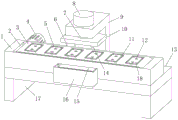
Fig. 1 is a schematic structural view of a continuous stamping die provided by the present invention.
Fig. 2 is a sectional view of the continuous stamping die provided by the present invention, which is connected with the transmission belt and the roller.
Fig. 3 is the utility model provides a continuous stamping die's motor and placing seat connection diagram.
In the figure: the device comprises a mounting seat 1, a placing groove 2, a transmission belt 3, a motor 4, a positioning plate 5, a first male die 6, an expansion link 7, a hydraulic device 8, a supporting frame 9, a top seat 10, a first through hole 11, a second through hole 12, a base 13, a second male die 14, an inclined groove 15, a collecting box 16, a supporting column 17, a positioning groove 18, a belt 19, a supporting seat 20, a roller 21, a rotating shaft 22, a placing seat 23 and a belt pulley 24.
Detailed Description
The technical solutions in the embodiments of the present invention will be described clearly and completely with reference to the accompanying drawings in the embodiments of the present invention, and it is obvious that the described embodiments are only some embodiments of the present invention, not all embodiments.
Referring to fig. 1-3, a continuous stamping die, including base 13, a plurality of support columns 17 of bottom fixedly connected with of base 13, top one side fixedly connected with mount pad 1 of base 13, the coaxial standing groove 2 that is equipped with in mount pad 1, the symmetry is equipped with two cylinders 21 in the standing groove 2, cylinder 21 rotates through the one end of pivot 22 and connects on standing groove 2 inner wall, the other end of pivot 22 extends to the outside of mount pad 1, be located coaxial fixedly connected with belt pulley 24 in the pivot 22 of mount pad 1 outside, be connected through belt 19 between two belt pulleys 24, coaxial fixedly connected with motor 4 in the pivot 22 of one side, motor 4 bottom fixed connection is at the top of base 13, utility model discloses when using, connect through wire and power supply unit.
A transmission belt 3 is connected between the two rollers 21, positioning plates 5 are fixedly connected on the transmission belt 3 at equal intervals, positioning grooves 18 are coaxially arranged at the tops of the positioning plates 5, first through holes 11 and second through holes 12 are formed in the positioning grooves 18, the positioning plates 5 are flexible plates, when the transmission belt 3 rotates, the flexible plates are arranged to facilitate the rotation of the positioning plates 5 on the outer walls of the rollers 21, supporting seats 20 are fixedly connected between the inner walls of the placing grooves 2, the supporting seats 20 are positioned between the transmission belts 3 on the two sides, the tops of the supporting seats 20 are tangent to the transmission belt 3, the areas of the supporting seats 20 are larger than those of the two positioning plates 5, the transmission belts 3 of the supporting seats 20 are arranged in a tangent mode, the supporting seats 20 can support the positioning plates 5 in the stamping process, the normal stamping is further ensured, a supporting frame 9 is fixedly connected on one side, far away, one side telescopic connection of hydraulic means 8 has last module, goes up module and 20 position correspondences of supporting seat, and supporting seat 20 bottoms are equipped with collection device.
The utility model discloses the locating plate 5 that sets up can advance line location to the stamping workpiece that needs the punching press and place, make placing that the stamping workpiece can be stable, and then guaranteed the accuracy of punching press, and twice punching press can be accomplished to the corresponding position between supporting seat 20 and the locating plate 5, and supporting seat 20 has played the effect of support and lower mould, waste material accessible inclined groove 15 after the punching press slides to the collecting box 16 in simultaneously, can play the effect of quick collection, motor 4 rotates and drives locating plate 5 and removes, remove to the first terrace die 6 of adjacent position department setting, a punching press can be accomplished to second terrace die 14, simple structure and guaranteed going on fast of punching press.
Specifically, when carrying out the punching press, place the stamping workpiece in the constant head tank 18 at locating plate 5 top, under the drive of transmission band 3, remove to the position department at supporting seat 20 place, hydraulic means 8 promotes mount pad 1 and drives first terrace die 6, second terrace die 14 and carries out stamping operation to the stamping workpiece, and the waste material after the punching press falls to the inclined groove 15 in, and the setting of inclined groove 15 is favorable to the quick landing of waste material to be collected in collecting box 16.
Referring to fig. 1, 2 and 3, further, the upper module includes a top seat 10, the hydraulic device 8 is connected to the top seat 10 through an expansion link 7, a first male die 6 and a second male die 14 are vertically connected to one side of the top seat 10 close to the mounting seat 1, the first male die 6 and the second male die 14 respectively correspond to the first through hole 11 and the second through hole 12, and the first male die 6 and the second male die 14 further extend into the first through hole 11 and the second through hole 12.
When the hydraulic device 8 is used, the device is fixedly connected with a power supply device through a lead.
Referring to fig. 1, further, the collecting device includes an inclined groove 15, the inclined groove 15 is fixedly connected to the bottom of the supporting base 20, one end of the inclined groove 15 is disposed through the side wall of the placing groove 2, and the collecting box 16 is fixedly connected to the outer wall of the mounting base 1 at a position corresponding to the position.
The setting of inclined groove 15 makes the waste material after the punching press can slide down, and then makes the waste material can be quick remove to the collecting box 16 in, has realized quick garbage collection.
Referring to fig. 2 and 3, further, a placing seat 23 is fixedly connected to the top of the base 13, and the motor 4 is fixedly connected to the top of the placing seat 23.
The provision of the placing seat 23 improves the stability of placing the motor 4 on top of the base 13.
The above, only be the concrete implementation of the preferred embodiment of the present invention, but the protection scope of the present invention is not limited thereto, and any person skilled in the art is in the technical scope of the present invention, according to the technical solution of the present invention and the utility model, the concept of which is equivalent to replace or change, should be covered within the protection scope of the present invention.
Claims (4)
1. The continuous stamping die comprises a base (13) and is characterized in that a plurality of supporting columns (17) are fixedly connected to the bottom of the base (13), a mounting seat (1) is fixedly connected to one side of the top of the base (13), a placing groove (2) is coaxially arranged in the mounting seat (1), two rollers (21) are symmetrically arranged in the placing groove (2), one end of each roller (21) is rotatably connected to the inner wall of the placing groove (2) through a rotating shaft (22), the other end of each rotating shaft (22) extends to the outside of the mounting seat (1), belt pulleys (24) are coaxially and fixedly connected to the rotating shaft (22) outside the mounting seat (1), the two belt pulleys (24) are connected through a belt (19), a motor (4) is coaxially and fixedly connected to the rotating shaft (22) on one side, and the bottom of the motor (4) is fixedly connected to the top of the base (13), a transmission belt (3) is connected between the two rollers (21), a positioning plate (5) is fixedly connected with the transmission belt (3) at equal intervals, a positioning groove (18) is coaxially arranged at the top of the positioning plate (5), a first through hole (11) and a second through hole (12) are arranged in the positioning groove (18), the positioning plate (5) is a flexible plate, a supporting seat (20) is fixedly connected between the inner walls of the placing groove (2), the supporting seat (20) is positioned between the transmission belts (3) at the two sides, the top of the supporting seat (20) is tangent to the transmission belt (3), the area of the supporting seat (20) is larger than that of the two positioning plates (5), a supporting frame (9) is fixedly connected to one side of the base (13) far away from the mounting seat (1), a hydraulic device (8) is fixedly connected to the supporting frame (9), and an upper module is telescopically, the upper module corresponds to the support seat (20), and a collecting device is arranged at the bottom of the support seat (20).
2. The continuous stamping die according to claim 1, wherein the upper module comprises a top seat (10), the hydraulic device (8) is connected with the top seat (10) through an expansion rod (7), one side of the top seat (10) close to the mounting seat (1) is vertically connected with a first male die (6) and a second male die (14), the first male die (6) and the second male die (14) respectively correspond to the first through hole (11) and the second through hole (12), and the first male die (6) and the second male die (14) further extend into the first through hole (11) and the second through hole (12).
3. The continuous stamping die according to claim 1, characterized in that the collecting device comprises an inclined groove (15), the inclined groove (15) is fixedly connected to the bottom of the supporting base (20), one end of the inclined groove (15) is arranged through the side wall of the placing groove (2), and a collecting box (16) is fixedly connected to the corresponding position of the outer wall of the mounting base (1).
4. A continuous stamping die according to claim 1, characterised in that a placing seat (23) is fixedly connected to the top of the base (13), and the motor (4) is fixedly connected to the top of the placing seat (23).
Priority Applications (1)
| Application Number | Priority Date | Filing Date | Title |
|---|---|---|---|
| CN201920845820.9U CN210208294U (en) | 2019-06-06 | 2019-06-06 | Continuous stamping die |
Applications Claiming Priority (1)
| Application Number | Priority Date | Filing Date | Title |
|---|---|---|---|
| CN201920845820.9U CN210208294U (en) | 2019-06-06 | 2019-06-06 | Continuous stamping die |
Publications (1)
| Publication Number | Publication Date |
|---|---|
| CN210208294U true CN210208294U (en) | 2020-03-31 |
Family
ID=69930178
Family Applications (1)
| Application Number | Title | Priority Date | Filing Date |
|---|---|---|---|
| CN201920845820.9U Active CN210208294U (en) | 2019-06-06 | 2019-06-06 | Continuous stamping die |
Country Status (1)
| Country | Link |
|---|---|
| CN (1) | CN210208294U (en) |
Cited By (2)
| Publication number | Priority date | Publication date | Assignee | Title |
|---|---|---|---|---|
| CN114589202A (en) * | 2022-03-17 | 2022-06-07 | 浙江博凡实业有限公司 | Finish rolling mill who possesses dust removal function |
| CN114798980A (en) * | 2022-04-06 | 2022-07-29 | 安徽联盈控电子科技有限公司 | Continuous pin trimming device for capacitor production and processing and use method thereof |
-
2019
- 2019-06-06 CN CN201920845820.9U patent/CN210208294U/en active Active
Cited By (2)
| Publication number | Priority date | Publication date | Assignee | Title |
|---|---|---|---|---|
| CN114589202A (en) * | 2022-03-17 | 2022-06-07 | 浙江博凡实业有限公司 | Finish rolling mill who possesses dust removal function |
| CN114798980A (en) * | 2022-04-06 | 2022-07-29 | 安徽联盈控电子科技有限公司 | Continuous pin trimming device for capacitor production and processing and use method thereof |
Similar Documents
| Publication | Publication Date | Title |
|---|---|---|
| CN211965671U (en) | Automatic blanking machine of stamping device | |
| CN210208294U (en) | Continuous stamping die | |
| CN209318583U (en) | A kind of press support plate Production of Stamping Die turnover device | |
| CN101752113B (en) | Keyboard assembly machine | |
| CN210208298U (en) | Automobile protective cover machining die convenient for material taking | |
| CN107962091A (en) | A kind of waste steel plate recycling apparatus for bending, the method with device recycling waste steel plate | |
| CN211386522U (en) | Stamping die is used in processing of high-speed ladder pressure baffle | |
| CN206492821U (en) | A kind of automatic die cutting removes the device of waste material | |
| CN219233674U (en) | Multistation integration stamping mechanism | |
| CN216881234U (en) | Stamping die capable of stamping continuously | |
| CN210305250U (en) | Automatic stamping device of convenient operation's aluminum plate | |
| CN217044149U (en) | Continuous stamping die for metal stamping | |
| CN214517004U (en) | Punch press convenient to collect waste material | |
| CN211544020U (en) | Electronic product packaging assembly line | |
| CN114378578A (en) | Type-C kludge | |
| CN211054405U (en) | Multi-station full-automatic dust removal film laminating machine | |
| CN106098857A (en) | The production technology of solar bracket assembly | |
| CN106410263A (en) | Automatic production equipment of lithium battery busbar upper polar column | |
| CN201905191U (en) | Automatic bean curd presser | |
| CN220515166U (en) | Hydraulic forming device | |
| CN221158260U (en) | Switch processing equipment | |
| CN220658878U (en) | Continuous stamping die for metal stamping | |
| CN211101697U (en) | Manufacturing equipment for tension wheel | |
| CN220717505U (en) | Base overturning stamping die | |
| CN220972637U (en) | Facial mask contour cutting device for repairing and pasting processing |
Legal Events
| Date | Code | Title | Description |
|---|---|---|---|
| GR01 | Patent grant | ||
| GR01 | Patent grant |