CN210198364U - Single-leg double-leg measuring foot stand for composite level - Google Patents
Single-leg double-leg measuring foot stand for composite level Download PDFInfo
- Publication number
- CN210198364U CN210198364U CN201921283696.8U CN201921283696U CN210198364U CN 210198364 U CN210198364 U CN 210198364U CN 201921283696 U CN201921283696 U CN 201921283696U CN 210198364 U CN210198364 U CN 210198364U
- Authority
- CN
- China
- Prior art keywords
- rotating shaft
- transverse rotating
- moving block
- transverse
- leg
- Prior art date
- Legal status (The legal status is an assumption and is not a legal conclusion. Google has not performed a legal analysis and makes no representation as to the accuracy of the status listed.)
- Withdrawn - After Issue
Links
- 239000002131 composite material Substances 0.000 title abstract description 14
- 150000001875 compounds Chemical class 0.000 claims description 13
- 238000005259 measurement Methods 0.000 claims description 11
- 125000004122 cyclic group Chemical group 0.000 claims description 10
- 239000003381 stabilizer Substances 0.000 claims description 5
- 239000002184 metal Substances 0.000 description 4
- 238000000034 method Methods 0.000 description 4
- 238000010586 diagram Methods 0.000 description 3
- 239000000463 material Substances 0.000 description 3
- 230000009977 dual effect Effects 0.000 description 2
- 230000000694 effects Effects 0.000 description 2
- 238000000354 decomposition reaction Methods 0.000 description 1
- 238000006073 displacement reaction Methods 0.000 description 1
- 230000010354 integration Effects 0.000 description 1
- 230000001360 synchronised effect Effects 0.000 description 1
Images




Landscapes
- Length-Measuring Instruments Using Mechanical Means (AREA)
Abstract
The utility model discloses a single-leg double-leg measuring foot rest for a composite level, which has simple structure and easy operation and can ensure the stability of the composite level, the horizontal supporting piece is fixed on the outer side face of the middle of the annular base, a first horizontal rotating shaft parallel to or perpendicular to the outer side face of the middle of the annular base is connected with the horizontal supporting piece, a first moving block capable of axially moving along the first horizontal rotating shaft and axially rotating around the first horizontal rotating shaft is connected to the first horizontal rotating shaft in a sleeved mode, the lower portion of the first moving block is connected to a second horizontal rotating shaft in a sleeved mode, the horizontal projection axial directions of the first horizontal rotating shaft and the second horizontal rotating shaft are perpendicular to each other, a second moving block capable of axially moving along the second horizontal rotating shaft and axially rotating around the second horizontal rotating shaft is connected to the second horizontal rotating shaft in a sleeved mode, a supporting leg is arranged at the lower end of the second moving block, two supporting legs are arranged on two sides of the lower end of.
Description
Technical Field
The utility model relates to a measure auxiliary device, especially a foot rest is measured with single leg bi-polar leg to compound level that simple structure, easy operation, can guarantee compound level stability.
Background
Chinese patent No. 201220611636.6 discloses a "dual-type composite level for observing ruler and instrument" (hereinafter referred to as composite level), which is structurally provided with a cylindrical ruler body and a level, wherein a leveling staff parallel to the axis of the cylindrical ruler body and an observing unit capable of sliding up and down are fixed on the same cylindrical surface of the cylindrical ruler body, the observing unit is provided with a height signal measuring device and a height signal measuring device which are fixedly connected with each other, and the sighting axis of the height signal measuring device is perpendicular to the axis of the cylindrical ruler body. During leveling, need arrange the lower extreme of the cylindricality chi body (levelling rod) in on the auxiliary ruler pad, need use the fixed cylindricality chi body of three-legged foot rest (levelling rod) simultaneously, through observing behind the leveling of the cylindricality chi body (levelling rod) such as surveyor's level, observe … … again. This patent application settles the surveyor's level on the levelling staff for the first time, has realized the integration of surveyor's level and levelling staff, can adopt dual observation principle, changes traditional leveling device's three-point configuration into two-point configuration to realized dual system's synchronous observation, overcome the not enough that prior art exists. The patent number 201220373858.9's chinese utility model patent discloses a "collet formula measurement foot rest", changes the outer base of traditional foot rest for cyclic annular (collet formula structure) by flat (cloud platform formula structure), provides dedicated measurement foot rest for compound surveyor's level (and measure the scale) for the first time, has improved the vertically upright accuracy of compound surveyor's level (and measure the scale). The chinese utility model patent No. 201310022381.9 discloses a "clasping type measuring foot rest", which further adopts the orthogonal decomposition adjustment principle to improve the "colleting type measuring foot rest", so as to accelerate the adjustment speed of the upright state of the composite level (and the measuring staff). The patent number is 201610159164.8's chinese utility model patent, but discloses a "but measurement foot rest of accurate adjustment scale angle", has scale anchor clamps and has the cyclic annular base of open-ended, the middle part medial surface of cyclic annular base meets through vertical pivot and scale anchor clamps, it has the roof spring that is located vertical axis one side and is located the vertical axis opposite side and fix the horizontal jackscrew on cyclic annular base to connect mutually between cyclic annular base and scale anchor clamps, it has three stabilizer blades (three landing legs), two stabilizer blades (two landing legs) or single leg two stabilizer blades to connect mutually with cyclic annular base. Although the problem of horizontal rotation of the composite level (and the measuring staff) is solved, the composite level (and the measuring staff) can accurately face (aim at) the opposite side composite level. However, in practice the following disadvantages are found: (1) the leveling device adopts three support legs (three support legs), the three support legs and the leveling staff form four landing points, the leveling of the leveling staff is difficult to adjust, and the practicability is poor; (2) the double-support leg (double-support leg) is adopted, so that the stability of the composite level can be guaranteed, the operation is complex, and the feet of a measurer cannot move, so that time and labor are wasted; (2) if the single-leg double-leg structure is adopted, although the operation is simple, the stability is poor, the precision of the composite level is influenced, and even the measurement requirement cannot be met.
SUMMERY OF THE UTILITY MODEL
The utility model relates to a solve the above-mentioned technical problem that prior art exists, provide a simple structure, easy operation, can guarantee the compound level for the compound level single foot double-pivot measure foot rest of compound level stability.
The technical solution of the utility model is that: a single-leg double-leg measuring foot stand for a composite level gauge comprises a scale clamp and an annular base, wherein the inner side surface of the middle part of the annular base is connected with the scale clamp through a vertical rotating shaft, a top spring positioned on one side of a vertical shaft and a transverse jackscrew positioned on the other side of the vertical shaft and fixed on the annular base are connected between the annular base and the scale clamp, a transverse support member is fixed on the outer side surface of the middle part of the annular base and is connected with a first transverse rotating shaft parallel or vertical to the outer side surface of the middle part of the annular base, a first moving block is sleeved on the first transverse rotating shaft, the lower part of the first moving block is sleeved on a second transverse rotating shaft, the horizontal projection axial directions of the first transverse rotating shaft and the second transverse rotating shaft are mutually vertical, a second moving block is sleeved on the second transverse rotating shaft, the lower end of the second moving block is provided with a leg, and, the connecting line of the corresponding points of the two support legs is parallel to the outer side surface of the middle part of the annular base;
if the transverse supporting piece is rotationally connected with the first transverse rotating shaft, the first transverse rotating shaft is in threaded connection with the first moving block;
if the transverse supporting piece is in threaded connection with the first transverse rotating shaft, the first transverse rotating shaft is in rotational connection with the first moving block;
if the second transverse rotating shaft is rotationally connected with the first moving block, the second transverse rotating shaft is in threaded connection with the second moving block;
if the second transverse rotating shaft is in threaded connection with the first moving block, the second transverse rotating shaft is in rotational connection with the second moving block.
The first transverse rotating shaft is sleeved with a first moving block which can axially move along the first transverse rotating shaft and axially rotate around the first transverse rotating shaft, the lower portion of the first moving block is sleeved on the second transverse rotating shaft, the horizontal projection axial directions of the first transverse rotating shaft and the second transverse rotating shaft are mutually vertical, the second transverse rotating shaft is sleeved with a second moving block which can axially move along the second transverse rotating shaft and axially rotate around the second transverse rotating shaft, the lower end of the second moving block is provided with a supporting leg, two supporting legs are arranged on two sides of the lower end of the supporting leg, and the corresponding point connecting line of the two supporting legs is parallel to the outer side surface of the middle portion of the annular base.
The transverse supporting pieces are two first fixing plates which are parallel to each other and perpendicular to the outer side face of the middle of the annular base, the first transverse rotating shaft is rotatably connected with the two first fixing plates and perpendicular to each other, the first transverse rotating shaft is in threaded connection with the first moving block, the first moving block is in threaded connection with the second transverse rotating shaft, the second moving block is two second fixing plates which are parallel to each other, the second fixing plates are perpendicular to the second transverse rotating shaft and rotatably connected with each other, the lower ends of the second fixing plates are connected with the supporting legs, the lower ends of the supporting legs are connected with the transverse plates, and the two supporting legs are fixed below the transverse plates.
The transverse supporting piece is of a block structure, the first transverse rotating shaft is in threaded connection with the supporting piece and is parallel to the outer side face of the middle of the annular base, the upper portion of the first moving block is provided with two third fixing plates which are parallel to each other, perpendicular to the first transverse rotating shaft and in rotating connection with the first transverse rotating shaft, the lower portion of the first moving block is in threaded connection with the second transverse rotating shaft, the second moving block is provided with two second fixing plates which are parallel to each other, the second fixing plates are perpendicular to the second transverse rotating shaft and in rotating connection with the second transverse rotating shaft, and the lower ends of the second fixing plates are connected.
The transverse supporting piece is a rectangle with an opening at the bottom and composed of two side plates and an upper plate, the two side plates are parallel to the outer side surface of the middle part of the annular base, the first transverse rotating shaft vertically penetrates through the two side plates and is rotatably connected with the two side plates, the lower part of the first moving block is in threaded connection with the second transverse rotating shaft, the second moving block is two second fixing plates which are parallel to each other, the second fixing plates are perpendicular to the second transverse rotating shaft and are rotatably connected with the second transverse rotating shaft, and the lower ends of the second fixing plates are connected with the supporting legs.
The transverse supporting piece is a rectangle with an opening at the bottom, the two side plates are parallel to the outer side face of the middle of the annular base, the first transverse rotating shaft vertically penetrates through the two side plates and is connected with the two side plates in a rotating mode, the lower portion of the first moving block is provided with two fourth fixing plates which are parallel to each other and parallel to the first transverse rotating shaft, and the second transverse rotating shaft is perpendicular to the two fourth fixing plates and is connected with the two fourth fixing plates in a rotating mode.
The utility model provides a foot rest is measured to two stabilizer blades of single leg, simple structure, both adjustable single leg position all around for the level of scale, also can adjust single leg for the inclination of scale, both ensured the stability that compound surveyor's level scale erect, made things convenient for surveyor's operation again, labour saving and time saving has improved work efficiency.
Drawings
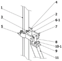
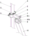
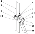
Fig. 1, 2 and 3 are schematic structural diagrams of embodiment 1 of the present invention.
Fig. 4 is a usage effect diagram of embodiment 1 of the present invention.
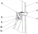
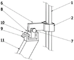
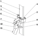
Fig. 5, 6 and 7 are schematic structural views of embodiment 2 of the present invention.
Fig. 8 is a usage effect diagram of embodiment 2 of the present invention.
Fig. 9 and 10 are schematic structural views of embodiment 3 of the present invention.
Fig. 11 and 12 are schematic structural views of embodiment 4 of the present invention.
Detailed Description
Example 1
As shown in fig. 1, 2 and 3: the scale fixture comprises a scale fixture 1 made of metal and the like and an annular base 2 with an opening, the scale fixture 1 is arranged in the annular base 2, the middle of the inner side surface of the annular base 2 is connected with the scale fixture 1 through a vertical rotating shaft 3, the difference from the prior art is that the outer side surface of the middle of the annular base 2 is fixedly provided with a transverse support 6, the transverse support 6 is two first fixing plates 6-1 which are parallel to each other and vertical to the outer side surface of the middle of the annular base 2, a first transverse rotating shaft 7 vertically penetrates through the two first fixing plates 6-1 and is connected with the first fixing plates 6-1 in a rotating mode, and the first transverse rotating shaft 7 is in threaded connection with the upper portion of a first moving block 8, so that the first moving block 8 can axially move along the first transverse rotating shaft 7 and axially rotate around the first transverse rotating. The lower portion of the first moving block 8 is in threaded connection with a second transverse rotating shaft 9, horizontal projection axes of the first transverse rotating shaft 7 and the second transverse rotating shaft 9 are perpendicular to each other, and a second moving block 10 is in rotary connection with the second transverse rotating shaft 9, so that the second moving block 10 can axially move along the second transverse rotating shaft 9 and axially rotate around the second transverse rotating shaft 9. The second moving block 10 is two second fixing plates 10-1 which are parallel to each other and perpendicular to the second transverse rotating shaft 9, the lower ends of the second fixing plates 10-1 can be connected with one supporting leg 11 through a connecting plate, the lower end of the supporting leg 11 is connected with a transverse plate 13, two supporting legs 12 are fixed below the transverse plate 13, and the connecting line of corresponding points (the same structure points on the two supporting legs) of the two supporting legs 12 is parallel to the outer side face of the middle part of the annular base 2. In order to facilitate the rotation of the first transverse rotating shaft 7 relative to the transverse support member 6 and the second moving block 10 relative to the second transverse rotating shaft 9, in order to prevent the first transverse rotating shaft 7 from moving axially relative to the transverse support member 6 and the second transverse rotating shaft 9 relative to the second moving block 10, a locking device may be provided at both ends of the first transverse rotating shaft 7 and the second transverse rotating shaft 9.
The measuring operation process is shown in FIG. 4: the measuring scale is placed in the scale clamp 1 and fixed by a fixing member. The bottom of the measuring staff is placed on a leveling mark point, two support legs 12 are located on the ground, the measuring staff is approximately in a vertical state by adjusting the horizontal position of the support legs 12, then the measuring staff is accurately in the vertical state by rotating a first transverse rotating shaft 7 and a second transverse rotating shaft 9, and then the jackscrew 5 is finely adjusted, so that the vertical measuring staff horizontally rotates along a vertical shaft 3, and the jackscrew 5 and the spring 4 jointly act to enable the measuring staff to accurately face the composite level of the other side.
Example 2:
as shown in fig. 5, 6 and 7: the same with prior art, be equipped with scale anchor clamps 1 that materials such as metal made and have open-ended annular base 2, scale anchor clamps 1 are arranged in annular base 2, the medial surface middle part of annular base 2 meets through vertical pivot 3 with scale anchor clamps 1, different with prior art is that annular base 2 middle part lateral surface is fixed with horizontal support piece 6, horizontal support piece 6 is massive structure, with the parallel 7 threaded connection of first horizontal pivot of annular base 2 middle part lateral surface in horizontal support piece 6, first horizontal pivot 7 rotates with first movable block 8 upper portion to be connected, make first movable block 8 can follow 7 axial displacement of first horizontal pivot and around 7 axial rotations of first horizontal pivot. The upper portion of the first moving block 8 is provided with two third fixing plates 8-1 which are parallel to each other and perpendicular to the first transverse rotating shaft 7, the lower portion of the first moving block 8 is in threaded connection with a second transverse rotating shaft 9, horizontal projection axial directions of the first transverse rotating shaft 7 and the second transverse rotating shaft 9 are perpendicular to each other, and a second moving block 10 is rotationally connected with the second transverse rotating shaft 9, so that the second moving block 10 can axially move along the second transverse rotating shaft 9 and axially rotate around the second transverse rotating shaft 9. The second moving block 10 is two second fixing plates 10-1 which are parallel to each other and perpendicular to the second transverse rotating shaft 9, the lower end of the second fixing plate 10-1 is connected with one supporting leg 11 through a connecting plate, the lower end of the supporting leg 11 is provided with two supporting feet 12, and the connecting line of corresponding points (the same structure points on the two supporting feet) of the two supporting feet 12 is parallel to the outer side surface of the middle part of the annular base 2.
The procedure for the measurement was the same as in example 1 (see FIG. 8).
Example 3:
as shown in fig. 9 and 10: the same as the prior art, a scale clamp 1 made of metal and other materials and an annular base 2 with an opening are arranged, the scale clamp 1 is arranged in the annular base 2, the middle part of the inner side surface of the annular base 2 is connected with the scale clamp 1 through a vertical rotating shaft 3, different from the prior art, a transverse supporting piece 6 is fixed on the outer side surface of the middle part of the annular base 2, the transverse supporting piece 6 is a rectangle with an opening on the bottom surface and is composed of two side plates 6-2 and an upper panel, the two side plates 6-2 are parallel to the outer side surface of the middle part of the annular base 2, a first transverse rotating shaft 7 which is vertical to the outer side surface of the middle part of the annular base 2 passes through the two side plates 6-2 and is rotatably connected with the side plates 6-2, the first transverse rotating shaft 7 is in threaded connection with the upper part of a first moving block 8, so that the first moving block 8 can move axially along the first traverse rotation axis 7 and rotate axially about the first traverse rotation axis 7. The lower portion of the first moving block 8 is in threaded connection with a second transverse rotating shaft 9, horizontal projection axes of the first transverse rotating shaft 7 and the second transverse rotating shaft 9 are perpendicular to each other, and a second moving block 10 is in rotary connection with the second transverse rotating shaft 9, so that the second moving block 10 can axially move along the second transverse rotating shaft 9 and axially rotate around the second transverse rotating shaft 9. The second moving block 10 is two second fixing plates 10-1 which are parallel to each other and perpendicular to the second traverse rotation axis 9, the lower ends of the second fixing plates 10-1 are connected with one leg 11 through a connecting plate, and the structure of the lower end of the leg 11 is the same as that of embodiment 1 or embodiment 2.
The procedure for the measurement was the same as in example 1.
Example 4:
as shown in fig. 11 and 12: the same as the prior art, a scale clamp 1 made of metal and other materials and an annular base 2 with an opening are arranged, the scale clamp 1 is arranged in the annular base 2, the middle part of the inner side surface of the annular base 2 is connected with the scale clamp 1 through a vertical rotating shaft 3, different from the prior art, a transverse supporting piece 6 is fixed on the outer side surface of the middle part of the annular base 2, the transverse supporting piece 6 is a rectangle with an opening on the bottom surface and is composed of two side plates 6-2 and an upper panel, the two side plates 6-2 are parallel to the outer side surface of the middle part of the annular base 2, a first transverse rotating shaft 7 which is vertical to the outer side surface of the middle part of the annular base 2 passes through the two side plates 6-2 and is rotatably connected with the two side plates (6-2), the first transverse rotating shaft 7 is in threaded connection with the upper part of a first moving block 8, so that the first moving block 8 can move axially along the first traverse rotation axis 7 and rotate axially about the first traverse rotation axis 7. The lower portion of the moving block 8 is provided with two fourth fixing plates 8-2 which are parallel to each other and parallel to the first transverse rotating shaft 7, the two fourth fixing plates 8-2 are rotatably connected with a second transverse rotating shaft 9 which is perpendicular to the fourth fixing plates 8-2, the horizontal projection axial directions of the first transverse rotating shaft 7 and the second transverse rotating shaft 9 are perpendicular to each other, and the second moving block 10 is in threaded connection with the second transverse rotating shaft 9, so that the second moving block 10 can axially move along the second transverse rotating shaft 9 and axially rotate around the second transverse rotating shaft 9. The second moving block 10 is a block structure, the lower end of the second moving block 10 is connected to one leg 11, and the structure of the lower end of the leg 11 is the same as that of embodiment 1 or embodiment 2.
The procedure for the measurement was the same as in example 1.
Claims (5)
1. The utility model provides a foot rest is measured with two stabilizer blades of single leg to compound level, has scale anchor clamps (1) and cyclic annular base (2), the middle part medial surface of cyclic annular base (2) meets through vertical axis (3) and scale anchor clamps (1), has connect top spring (4) that are located vertical axis (3) one side and lie in vertical axis (3) opposite side and fix horizontal jackscrew (5) on cyclic annular base (2) between cyclic annular base (2) and scale anchor clamps (1), its characterized in that: a transverse supporting piece (6) is fixed on the outer side surface of the middle part of the annular base (2), a first transverse rotating shaft (7) which is parallel to or perpendicular to the outer side surface of the middle part of the annular base (2) is connected with the transverse supporting piece (6), a first moving block (8) is sleeved on the first transverse rotating shaft (7), the lower part of the first moving block (8) is sleeved on a second transverse rotating shaft (9), the horizontal projection axial directions of the first transverse rotating shaft (7) and the second transverse rotating shaft (9) are mutually perpendicular, a second moving block (10) is sleeved on the second transverse rotating shaft (9), a supporting leg (11) is arranged at the lower end of the second moving block (10), two supporting legs (12) are arranged on two sides of the lower end of the supporting leg (11), and the corresponding point connecting line of the two supporting legs (12) is parallel to the outer side surface of the;
if the transverse support (6) is rotationally connected with the first transverse rotating shaft (7), the first transverse rotating shaft (7) is in threaded connection with the first moving block (8);
if the transverse support (6) is in threaded connection with the first transverse rotating shaft (7), the first transverse rotating shaft (7) is in rotational connection with the first moving block (8);
if the second transverse rotating shaft (9) is rotationally connected with the first moving block (8), the second transverse rotating shaft (9) is in threaded connection with the second moving block (10);
if the second traverse shaft (9) is in threaded connection with the first moving block (8), the second traverse shaft (9) is in rotational connection with the second moving block (10).
2. The compound level foot rest for one-leg, two-leg measurement of claim 1, wherein: the transverse supporting piece (6) is two first fixing plates (6-1) which are parallel to each other and vertical to the outer side surface of the middle part of the annular base (2), the first transverse rotating shaft (7) is rotationally connected with the two first fixing plates (6-1) and is vertical to each other, the first transverse rotating shaft (7) is in threaded connection with a first moving block (8), the first moving block (8) is in threaded connection with a second transverse rotating shaft (9), the second moving block (10) is two second fixed plates (10-1) which are parallel to each other, the second fixing plate (10-1) is vertical to the second transverse rotating shaft (9) and is connected with the second transverse rotating shaft in a rotating way, the lower ends of the second fixing plates (10-1) are connected with supporting legs (11), the lower ends of the supporting legs (11) are connected with a transverse plate (13), and the two supporting legs (12) are fixed below the transverse plate (13).
3. The compound level foot rest for one-leg, two-leg measurement of claim 1, wherein: the transverse supporting piece (6) is of a block structure, the first transverse rotating shaft (7) is in threaded connection with the supporting piece (6) and is parallel to the outer side face of the middle of the annular base (2), the upper portion of the first moving block (8) is provided with two third fixing plates (8-1) which are parallel to each other, perpendicular to the first transverse rotating shaft (7) and rotationally connected with the first transverse rotating shaft, the lower portion of the first moving block (8) is in threaded connection with the second transverse rotating shaft (9), the second moving block (10) is provided with two second fixing plates (10-1) which are parallel to each other, the second fixing plates (10-1) are perpendicular to the second transverse rotating shaft (9) and rotationally connected with the second transverse rotating shaft, and the lower ends of the second fixing plates (10-1) are connected with the supporting legs.
4. The compound level foot rest for one-leg, two-leg measurement of claim 1, wherein: the transverse supporting piece (6) is a rectangle with an opening at the bottom and composed of two side plates (6-2) and an upper plate, the two side plates (6-2) are parallel to the outer side surface of the middle part of the annular base (2), the first transverse rotating shaft (7) vertically penetrates through the two side plates (6-2) and is rotatably connected with the two side plates (6-2), the lower part of the first moving block (8) is in threaded connection with the second transverse rotating shaft (9), the second moving block (10) is two second fixing plates (10-1) which are parallel to each other, the second fixing plates (10-1) are vertically and rotatably connected with the second transverse rotating shaft (9), and the lower ends of the second fixing plates (10-1) are connected with the supporting legs (11).
5. The compound level foot rest for one-leg, two-leg measurement of claim 1, wherein: the transverse supporting piece (6) is a rectangle with an opening at the bottom, the two side plates (6-2) and the upper plate form the rectangle, the two side plates (6-2) are parallel to the outer side face of the middle of the annular base (2), the first transverse rotating shaft (7) vertically penetrates through the two side plates (6-2) and is rotatably connected with the two side plates (6-2), the lower part of the first moving block (8) is provided with two fourth fixing plates (8-2) which are parallel to each other and parallel to the first transverse rotating shaft (7), and the second transverse rotating shaft (9) is perpendicular to the two fourth fixing plates (8-2) and is rotatably connected with the two fourth fixing plates (8-2).
Priority Applications (1)
| Application Number | Priority Date | Filing Date | Title |
|---|---|---|---|
| CN201921283696.8U CN210198364U (en) | 2019-08-09 | 2019-08-09 | Single-leg double-leg measuring foot stand for composite level |
Applications Claiming Priority (1)
| Application Number | Priority Date | Filing Date | Title |
|---|---|---|---|
| CN201921283696.8U CN210198364U (en) | 2019-08-09 | 2019-08-09 | Single-leg double-leg measuring foot stand for composite level |
Publications (1)
| Publication Number | Publication Date |
|---|---|
| CN210198364U true CN210198364U (en) | 2020-03-27 |
Family
ID=69864971
Family Applications (1)
| Application Number | Title | Priority Date | Filing Date |
|---|---|---|---|
| CN201921283696.8U Withdrawn - After Issue CN210198364U (en) | 2019-08-09 | 2019-08-09 | Single-leg double-leg measuring foot stand for composite level |
Country Status (1)
| Country | Link |
|---|---|
| CN (1) | CN210198364U (en) |
Cited By (1)
| Publication number | Priority date | Publication date | Assignee | Title |
|---|---|---|---|---|
| CN110296682A (en) * | 2019-08-09 | 2019-10-01 | 大连圣博尔测绘仪器科技有限公司 | Composite level measures foot prop with the double stabilizer blades of single leg |
-
2019
- 2019-08-09 CN CN201921283696.8U patent/CN210198364U/en not_active Withdrawn - After Issue
Cited By (2)
| Publication number | Priority date | Publication date | Assignee | Title |
|---|---|---|---|---|
| CN110296682A (en) * | 2019-08-09 | 2019-10-01 | 大连圣博尔测绘仪器科技有限公司 | Composite level measures foot prop with the double stabilizer blades of single leg |
| CN110296682B (en) * | 2019-08-09 | 2024-05-14 | 大连圣博尔测绘仪器科技有限公司 | Single-leg double-foot measuring foot stand for composite level |
Similar Documents
| Publication | Publication Date | Title |
|---|---|---|
| JP6739552B2 (en) | Stand for surveying instrument that can accurately adjust the angle of the staff | |
| CN106338325B (en) | A kind of skin Nano satellite quality, mass center and rotary inertia integrated measurer | |
| CN210198364U (en) | Single-leg double-leg measuring foot stand for composite level | |
| CN102777737A (en) | Sleeve clip type measurement tripod | |
| KR20180044753A (en) | Clinometer measurement device | |
| CN115950402A (en) | Building inclination observation device and measurement method | |
| CN110296682B (en) | Single-leg double-foot measuring foot stand for composite level | |
| CN211550976U (en) | Mounting tool of metering device | |
| CN205718770U (en) | Bearing outer ring height dimension test measuring device | |
| CN216593037U (en) | Building slope is surveyed and drawing chi for measurement | |
| CN218646295U (en) | Perpendicular auxiliary device suitable for survey and drawing sopwith staff | |
| CN213236646U (en) | Adjustable engineering measurement mark post | |
| CN202791187U (en) | Cartridge clip type measuring tripod | |
| CN109058680B (en) | Orthogonal scale foot rest | |
| CN206113922U (en) | Automatic perpendicular laser height finding levelling rod | |
| CN207687620U (en) | Liftable position rotating platform | |
| CN201497485U (en) | Conical surface roughness measuring device | |
| CN212482495U (en) | Building engineering is with straightness detection device that hangs down | |
| CN212029074U (en) | High-precision laser output mapping device | |
| CN211600029U (en) | Handheld distancer support frame is used in national soil space planning | |
| CN203414166U (en) | High-far degree controllable noise meter tripod | |
| CN207123253U (en) | A kind of steel pipe end surface detection tool for detecting verticality of bicylindrical positioning | |
| CN219319393U (en) | Mountain region measuring and positioning device | |
| CN218380980U (en) | Template gradient measuring device | |
| CN221223667U (en) | High-precision towing tank track level measuring device |
Legal Events
| Date | Code | Title | Description |
|---|---|---|---|
| GR01 | Patent grant | ||
| GR01 | Patent grant | ||
| AV01 | Patent right actively abandoned | ||
| AV01 | Patent right actively abandoned | ||
| AV01 | Patent right actively abandoned |
Granted publication date: 20200327 Effective date of abandoning: 20240514 |
|
| AV01 | Patent right actively abandoned |
Granted publication date: 20200327 Effective date of abandoning: 20240514 |