CN210152900U - Oil-gas separator for air compressor - Google Patents
Oil-gas separator for air compressor Download PDFInfo
- Publication number
- CN210152900U CN210152900U CN201921065445.2U CN201921065445U CN210152900U CN 210152900 U CN210152900 U CN 210152900U CN 201921065445 U CN201921065445 U CN 201921065445U CN 210152900 U CN210152900 U CN 210152900U
- Authority
- CN
- China
- Prior art keywords
- oil
- gas
- barrel
- air compressor
- flange
- Prior art date
- Legal status (The legal status is an assumption and is not a legal conclusion. Google has not performed a legal analysis and makes no representation as to the accuracy of the status listed.)
- Active
Links
Images


Abstract
The utility model provides an oil and gas separator for air compressor machine, it include the barrel, set up in oil-gas separation core in the barrel and set firmly in the oil gas cylinder gland on barrel top, the welding of barrel up end has and is used for connecting the first flange of oil gas cylinder gland, it is fixed through a plurality of cover fastening screws between oil gas cylinder gland and the first flange, be connected with pressure valve, outer oil return pipe, blow-down pipe and blast pipe on the barrel lateral wall, oil-gas separation core inside is equipped with interior oil return pipe, interior oil return pipe end-to-end connection has the oil return connection, the oil return connection passes the barrel lateral wall and with outer oil return union coupling. The utility model discloses an oil and gas separator has convenient maintenance, change, labour saving and time saving's characteristics.
Description
Technical Field
The utility model relates to an air compressor machine technical field, in particular to oil and gas separator for air compressor machine.
Background
The oil-gas separator is an important component in the oil-injection screw compressor and is responsible for separating lubricating oil in an oil-gas mixture discharged from a main machine of the compressor for recycling and ensuring that compressed gas discharged by a compressor unit is clean. The oil-gas separation core which plays the main function of oil-gas separation can be blocked in the using process, so that the pressure loss is increased, the separation effect is poor, and the oil-gas separation core needs to be replaced regularly. The replacement work of the oil-gas separation core is the most time and energy consuming part in the general maintenance work of the screw compressor, and accounts for more than 60 percent of the total workload.
Traditional oil and gas separator need demolish the back one by one with blast pipe, oil return pipe, blow-down pipe etc. on the oil gas section of thick bamboo gland earlier, just can open oil gas section of thick bamboo pressure, takes out inside oil-gas separation core, wastes time and energy.
In view of this, the utility model provides an oil and gas separator for air compressor machine that convenient maintenance, change to overcome the problem that above-mentioned prior art exists.
SUMMERY OF THE UTILITY MODEL
The utility model aims at providing a convenient oil and gas separator for air compressor machine of maintenance, change, it has solved the problem that above-mentioned prior art exists.
In order to achieve the above object, the utility model discloses a technical scheme be: the utility model provides an oil and gas separator for air compressor machine, its includes the barrel, set up in oil-gas separation core in the barrel and set firmly in the oil gas cylinder gland on barrel top, the welding of barrel up end has the first flange that is used for connecting oil gas cylinder gland, it is fixed through a plurality of cover fastening screws between oil gas cylinder gland and the first flange, connect in pressure valve, outer oil return pipe, blow-down pipe and blast pipe on the barrel lateral wall, oil-gas separation core inside is equipped with interior oil return pipe, interior oil return pipe end-to-end connection has the oil return connection, the oil return connection pass perpendicularly the barrel lateral wall and with outer oil return union coupling.
Further, a sealing gasket is adopted between the oil cylinder gland and the first flange for sealing.
Further, the emptying pipe is communicated with the inside of the cylinder body through an emptying pipe joint, the emptying pipe joint is close to the oil return port joint, and the emptying pipe joint and the oil return port joint are positioned on the same horizontal plane.
Further, the exhaust pipe is communicated with the interior of the barrel through a gas outlet joint, the gas outlet joint is close to the emptying pipe joint, and the outer end of the gas outlet joint is connected with the pressure valve.
Furthermore, the oil return port joint, the air outlet joint and the pressure valve are arranged above the oil-gas separation core.
Further, a second flange is welded inside the cylinder, the oil-gas separation core is installed on the second flange and is compressed through a separation core pressing plate, and the separation core pressing plate and the second flange are fixed through a plurality of pressing plate fastening screws.
Further, the barrel is further provided with a pressure gauge, an oil filling port connector and an oil observation mirror seat, the pressure gauge is located above the oil filling port connector, and the oil observation mirror seat is located below the oil filling port connector.
Further, the position of the oil filling port joint is lower than the positions of the emptying pipe joint and the air outlet joint.
Compared with the prior art, the utility model relates to an oil and gas separator's for air compressor machine beneficial effect: parts such as a pressure valve, an external oil return pipe, an emptying pipe and the like are all connected to the side wall of the cylinder body, other parts are not mounted on the oil-gas cylinder gland, and when the oil-gas separation core is replaced, the oil-gas separation core in the cylinder body is taken out only by opening the oil-gas cylinder gland, so that time and labor are saved; a second flange is welded in the cylinder, the oil-gas separation core is arranged on the second flange and is fixed and firmly pressed by a separation core pressing plate and a plurality of pressing plate fastening screws, and the fixing effect of the oil-gas separation core is good; adopt sealed pad to seal between oil cylinder gland and the first flange, can dismantle repeatedly the use.
Drawings
In order to more clearly illustrate the technical solutions of the embodiments of the present invention, the drawings used in the description of the embodiments are briefly introduced below, and it is obvious that the drawings in the following description are only some embodiments of the present invention, and for those skilled in the art, other drawings can be obtained without inventive work, wherein:
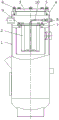
FIG. 1 is a structural diagram of an oil-gas separator of the present invention;
FIG. 2 is an exploded view of the oil-gas separator of the present invention;
FIG. 3 is a sectional view of the oil-gas separator of the present invention;
fig. 4 is a left side view of the oil-gas separator of the present invention.
Detailed Description
The present invention will be described in detail below with reference to the drawings, but it should be emphasized that the following embodiments are merely illustrative and are not intended to limit the scope and application of the present invention.
Referring to fig. 1 to 4, the oil-gas separator for an air compressor of the present invention is used for separating oil-gas mixture in compressed air, and includes a cylinder 1, an oil-gas separation core 2 disposed in the cylinder 1, and an oil-gas cylinder gland 3 fixedly disposed at the top end of the cylinder 1.
Referring to fig. 1 and 2, a first flange 4 for connecting an oil cylinder gland 3 is welded on the upper end surface of a cylinder body 1, the oil cylinder gland 3 and the first flange 4 are sealed by a gasket 5, and the oil cylinder gland 3 and the first flange 4 are fixed by a plurality of cylinder cap fastening screws 6 and can be repeatedly disassembled and assembled for use.
Referring to fig. 2 and 3, a second flange 7 is welded inside the cylinder 1, the oil-gas separation core 2 is mounted on the second flange 7 and is compressed by a separation core pressing plate 8, and the separation core pressing plate 8 and the second flange 7 are fixed by a plurality of pressing plate fastening screws 9.
Referring to fig. 1 and 2, an inner oil return pipe 10 is arranged inside the oil-gas separation core 2, the tail end of the inner oil return pipe 10 is connected with an oil return port connector 11, the oil return port connector 11 vertically penetrates through the side wall of the cylinder 1 to be exposed outwards, and meanwhile, the tail end of the part, exposed outwards, of the oil return port connector 11 is connected with an outer oil return pipe 12. The side wall of the barrel body 1 is also fixedly provided with a vent pipe joint 13 and an air outlet joint 14 which are communicated with the inside and the outside of the barrel body 1. Wherein, the vent pipe joint 13 is close to the oil return port joint 11 and the vent pipe joint and the oil return port joint are positioned on the same horizontal plane. The outer end of the emptying pipe joint 13 is connected with an emptying pipe 15. In addition, the air outlet joint 14 is close to the emptying pipe joint 13, the outer end of the air outlet joint 14 is connected with a pressure valve 16, and the pressure valve 16 is connected with an exhaust pipe 17. The oil return port joint 11, the air outlet joint 14 and the pressure valve 16 are arranged above the oil-gas separation core 2.
Referring to fig. 4, the cylinder 1 is further provided with a pressure gauge 18, a fuel filler joint 19 and an oil observation mirror base 20, the pressure gauge 18 is located above the fuel filler joint 19, and the oil observation mirror base 20 is located below the fuel filler joint 19. The oil filler joint 19 is positioned lower than the position of the air vent joint 13 and the air outlet joint 14.
The oil-gas separator of the utility model connects the pressure valve 16, the external oil return pipe 12, the blow-down pipe 15 and other parts to the side wall of the cylinder body 10, no other parts are arranged on the oil-gas cylinder gland 3, when the oil-gas separation core 2 is replaced, only the oil-gas cylinder gland 3 needs to be opened, and the oil-gas separation core 2 in the cylinder body 1 is taken out, thereby saving time and labor; a second flange 7 is welded in the cylinder 1, the oil-gas separation core 2 is arranged on the second flange 7 and is fixed and firmly pressed by a separation core pressing plate 8 and a plurality of pressing plate fastening screws 9, and the fixing effect of the oil-gas separation core 2 is good; the oil gas cylinder gland 3 and the first flange 4 are sealed by the sealing gasket 5, and can be repeatedly disassembled and assembled for use.
Of course, those skilled in the art should realize that the above-mentioned embodiments are only used for illustrating the present invention, and not for limiting the present invention, and that the changes and modifications to the above-mentioned embodiments are all within the scope of the appended claims as long as they are within the true spirit of the present invention.
Claims (8)
1. The utility model provides an oil and gas separator for air compressor machine, its include the barrel, set up in oil-gas separation core in the barrel and set firmly in the oil gas cylinder gland on barrel top, its characterized in that: the oil-gas separation device is characterized in that a first flange used for being connected with the oil-gas cylinder gland is welded on the upper end face of the cylinder body, the oil-gas cylinder gland and the first flange are fixed through a plurality of cylinder cover fastening screws, a pressure valve, an outer oil return pipe, an emptying pipe and an exhaust pipe are connected to the side wall of the cylinder body, an inner oil return pipe is arranged inside the oil-gas separation core, the tail end of the inner oil return pipe is connected with an oil return port connector, and the oil return port connector penetrates through the side wall of the cylinder body and is connected with.
2. An oil and gas separator for an air compressor as claimed in claim 1, wherein: and a sealing gasket is adopted between the oil cylinder gland and the first flange for sealing.
3. An oil and gas separator for an air compressor as claimed in claim 2, wherein: the emptying pipe is communicated with the interior of the barrel through an emptying pipe joint, the emptying pipe joint is close to the oil return port joint, and the emptying pipe joint and the oil return port joint are positioned on the same horizontal plane.
4. An oil and gas separator for an air compressor as claimed in claim 3, wherein: the exhaust pipe is communicated with the interior of the barrel through a gas outlet joint, the gas outlet joint is close to the emptying pipe joint, and the outer end of the gas outlet joint is connected with the pressure valve.
5. An oil and gas separator for an air compressor as claimed in claim 4, wherein: the oil return port connector, the air outlet connector and the pressure valve are arranged above the oil-gas separation core.
6. An oil and gas separator for an air compressor as claimed in claim 1, wherein: the oil-gas separation device is characterized in that a second flange is welded inside the cylinder, the oil-gas separation core is installed on the second flange and is compressed through a separation core pressing plate, and the separation core pressing plate and the second flange are fixed through a plurality of pressing plate fastening screws.
7. An oil and gas separator for an air compressor as claimed in claim 5, wherein: the oil filling device is characterized in that a pressure gauge, an oil filling port connector and an oil observation mirror seat are further arranged on the barrel, the pressure gauge is located above the oil filling port connector, and the oil observation mirror seat is located below the oil filling port connector.
8. An oil and gas separator for an air compressor as claimed in claim 7, wherein: the position of the oil filling port connector is lower than the positions of the emptying pipe connector and the air outlet connector.
Priority Applications (1)
| Application Number | Priority Date | Filing Date | Title |
|---|---|---|---|
| CN201921065445.2U CN210152900U (en) | 2019-07-09 | 2019-07-09 | Oil-gas separator for air compressor |
Applications Claiming Priority (1)
| Application Number | Priority Date | Filing Date | Title |
|---|---|---|---|
| CN201921065445.2U CN210152900U (en) | 2019-07-09 | 2019-07-09 | Oil-gas separator for air compressor |
Publications (1)
| Publication Number | Publication Date |
|---|---|
| CN210152900U true CN210152900U (en) | 2020-03-17 |
Family
ID=69765596
Family Applications (1)
| Application Number | Title | Priority Date | Filing Date |
|---|---|---|---|
| CN201921065445.2U Active CN210152900U (en) | 2019-07-09 | 2019-07-09 | Oil-gas separator for air compressor |
Country Status (1)
| Country | Link |
|---|---|
| CN (1) | CN210152900U (en) |
-
2019
- 2019-07-09 CN CN201921065445.2U patent/CN210152900U/en active Active
Similar Documents
| Publication | Publication Date | Title |
|---|---|---|
| CN210152900U (en) | Oil-gas separator for air compressor | |
| CN112354475B (en) | Sealing and compressing device | |
| CN204115975U (en) | A kind of diesel cylinder sleeve device for detecting sealability | |
| CN203892196U (en) | Separation oil tank of compressor | |
| CN210290069U (en) | Valve plate subassembly and air compressor machine | |
| CN216970405U (en) | Lubricating oil storage device | |
| CN103196030B (en) | Natural gas steam trap led by a kind of high pressure list | |
| CN217708890U (en) | Air pressure oil pumping device | |
| CN216618906U (en) | Neck-equipped welding flange for water pump | |
| CN213145676U (en) | Quick-mounting connecting flange for air pipe | |
| CN207364505U (en) | A kind of fastener and the air inlet pipe and cylinder cover attaching structure using the fastener | |
| CN204877961U (en) | Oil and gas separator filter core bottom oil return device | |
| CN212536698U (en) | Three-eccentric butterfly valve with valve seat blowing function | |
| CN209777609U (en) | High-efficient flexible collection device of granule material | |
| CN220860930U (en) | High-pressure gas filter cylinder | |
| CN218740823U (en) | Connection structure of air bag and pulse valve | |
| CN205102982U (en) | Single cylinder type engine oil level sensor equipment of leaking hunting | |
| CN207960886U (en) | Integral type length double compartment | |
| CN211649097U (en) | Pneumatic ball valve with double-layer sealing structure | |
| CN219013600U (en) | Manometer connecting pipe | |
| CN208766040U (en) | A kind of novel compression type Tool for Hydraulic | |
| CN217634379U (en) | Intercooler rubber tube connection structure of giving vent to anger convenient to dismouting | |
| CN212690945U (en) | Novel butterfly non-return combined valve | |
| CN209959378U (en) | Automobile engine resin intake manifold with replaceable pipeline connecting joint | |
| CN209838642U (en) | Cylinder body assembly with exhaust valve block limiting function |
Legal Events
| Date | Code | Title | Description |
|---|---|---|---|
| GR01 | Patent grant | ||
| GR01 | Patent grant |